Dynamical Defects in Rotating Magnetic Skyrmion Lattices
S. Pöllath,
1J. Wild,
1L. Heinen,
2T. N. G. Meier,
1M. Kronseder,
1L. Tutsch,
1A. Bauer,
3H. Berger,
4C. Pfleiderer,
3J. Zweck,
1A. Rosch,
2and C. H. Back
11
Institut für Experimentelle Physik, Universität Regensburg, Universitätsstraße 31, D-93040 Regensburg, Germany
2
Institut für Theoretische Physik, Universität zu Köln, D-50937 Köln, Germany
3
Physik-Department, Technische Universität München, D-85748 Garching, Germany
4
Crystal Growth Facility, École Polytechnique Fédérale de Lausanne, CH-1015 Lausanne, Switzerland (Received 16 January 2017; published 19 May 2017)
The chiral magnet Cu
2OSeO
3hosts a Skyrmion lattice that may be equivalently described as a superposition of plane waves or a lattice of particlelike topological objects. A thermal gradient may break up the Skyrmion lattice and induce rotating domains, raising the question of which of these scenarios better describes the violent dynamics at the domain boundaries. Here, we show that in an inhomogeneous temperature gradient caused by illumination in a Lorentz transmission electron microscope different parts of the Skyrmion lattice can be set into motion with different angular velocities. Tracking the time dependence, we show that the constant rearrangement of domain walls is governed by dynamic 5 – 7 defects arranging into lines. An analysis of the associated defect density is described by Frank ’ s equation and agrees well with classical 2D Monte Carlo simulations. Fluctuations of boundaries show a surgelike rearrangement of Skyrmion clusters driven by defect rearrangement consistent with simulations treating Skyrmions as point particles. Our findings underline the particle character of the Skyrmion.
DOI:10.1103/PhysRevLett.118.207205
In the last decade, a noncollinear topological spin texture, the Skyrmion, has attracted great attention representing a new type of topological soliton in magnetic materials.
Skyrmion lattices are periodic arrangements of a kind of magnetic whirls that may be found in a great variety of chiral magnets [1 – 12], as well as thin magnetic (multi)layers [13 – 16]. The topology of Skyrmions is encoded in a quantized winding number of the spin orientation. Emergent magnetic and electric fields describe the efficient coupling of the topological spin texture to electrons and magnons [17–20].
Skyrmion lattices may be described by two distinct approaches. In a wavelike picture as suggested, e.g., by small-angle neutron scattering (SANS) measurements, the Skyrmionic crystal may be accounted for by a super- position of three spin helices with their propagation vector rotated by 120° with respect to each other. From this point of view, the individual (solitonic) character of single Skyrmions vanishes in the collective. Note that, in most materials in the Skyrmion lattice phase, higher order scattering is basically absent; for MnSi, it is on the order of 10
−4, suggesting a rather smooth spin texture [21]. By contrast, in a particlelike picture, Skyrmions are viewed as individual solitonic particles. Indeed, individual Skyrmions have been observed early on [6,13], but the nonlinear character, as well as the degree of the particle character in the Skyrmion phase, remained unresolved. In fact, recent studies reveal strong deformation of the precise shape of Skyrmions under large strain [22].
The validity of either approach may be tested critically in studies of imperfect Skyrmion lattices, alluding to similar- ities with well-known atomic lattices, which also allows us
to verify particle conservation. In fact, the existence of defects and domains in Skyrmion lattices has been reported [23–26]; however, no comprehensive study focused on their dynamical properties has yet been performed. Here, we use time resolved nonstroboscopic cryo-Lorentz trans- mission electron microscopy (LTEM) to record domain boundaries and defects along with their fluctuations in the Skyrmion lattice phase of mechanically thinned Cu
2OSeO
3single crystals, and we find strong indications for the particlelike character of Skyrmions in this material. We analyze the motion of single defects and of grain bounda- ries in the Skyrmion lattice and perform a large statistical analysis of the defect density for a rich selection of misorientation angles Δθ between the Skyrmion domains.
As our main result, we find Skyrmion domains with high mobility, as well as a simultaneous surgelike rearrangement of many Skyrmions, triggered by magnon currents due to the temperature gradient introduced by the electron beam.
The fluctuating domain boundaries may be described by a combination of 5 – 7 defects, while the defect density increases with the misorientation angle between the grains.
The observed domain boundaries are similar to 2D dense packed lattices of colloidal crystals, bubble rafts, or even the nanonipple structure on the facet eyes of the morning cloak butterfly [27 – 29], which is rather spectacular since the latter systems consist of solid particles, while the Skyrmion is a continuous spin texture.
Our findings are supported by 2D Monte Carlo simu-
lations of the spin texture and by particle-based simulations
of the dynamics. They allow insights into the nature of this
peculiar lattice of topological spin objects and emphasize
its particlelike character. Particlelike properties are impor- tant and desired since future spintronic applications aim at controlling single Skyrmions [30].
For our study, we have selected the multiferroic insulator Cu
2OSeO
3, which is a prominent example for a bulk material hosting a Skyrmionic crystal [31], as observed in reciprocal space using SANS [32 – 34] and x-ray mag- netic scattering [25,35,36] and in real space via LTEM [8]
and magnetic force microscopy [37]. Defects of the Skyrmion phase of Cu
2OSeO
3were reported first by Rajeswari et al. [24] and Zhang et al., who studied a multidomain state by resonant x-ray scattering [25] with- out, however, further details.
The Cu
2OSeO
3single crystal was grown by the chemical vapor transport method and it was thinned in the ½110 direction, first mechanically and then by argon-ion milling technique down to a thickness of ≈100 nm. A few nano- meters of carbon were evaporated onto the thinned sample to minimize charging effects. LTEM images were taken with a FEI Tecnai F30 TEM in Lorentz mode where the magnetic field normal to the sample surface is tuned by the objective lens current. A defocused image with the Skyrmions is projected onto a phosphorescence screen and recorded through a lead glass window by a digital camera with a maximum of 90 frames = s. We controlled the temperature of the sample with a Gatan liquid helium sample holder. All data shown here were recorded using a constant temperature and an externally applied magnetic field of 18 K and 48 mT. The phase diagram was entered by
zero field cooling to 18 K and subsequently applying a magnetic field until the Skyrmion lattice phase is present in the whole field of view.
In a perfect Skyrmion lattice phase each Skyrmion is surrounded by six neighbors, which does not hold when differently oriented Skyrmion lattice domains are present.
In our experiments and simulations, we observe that the static and dynamic properties of domain boundaries are best described by 5 – 7 defects, i.e., two Skyrmions which have five and seven nearest neighbors, respectively. The coordination number of the defects depends on the geom- etry of the magnetic lattice, as can be seen from a comparison to recent investigations by Hagemeister et al.
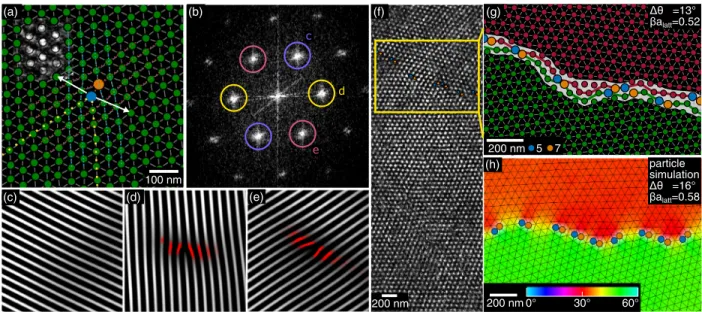
concerning defects in a Skyrmion square lattice [38]. A single 5–7 defect is shown in Fig. 1(a). The gray scale image in the upper left-hand corner displays the raw LTEM contrast after removal of image distortion. For details concerning image processing, see the Supplemental Material [39].
The Delaunay triangulation method is used to identify nearest neighbors. A closer look reveals the true nature of this defect: two disclination lines (the yellow dotted lines) join in the lattice node with five neighbors. Figures 1(c) – 1(e) show inverse Fourier transformations (FTs) of individual pairs of spots of the Skyrmion lattice’s typical six spot FT pattern, displayed in Fig. 1(b). The disclination lines can be identified directly as extra lines in Figs. 1(d) and 1(e) ending at the defect position. Deformations (in red) occur predomi- nantly perpendicular to the disclination lines. Figure 1(c)
(b)
(d) (e) (c)
e d c
Δθ =13°
βalatt=0.52
200 nm (g)
(h) particle
simulation Δθ =16°
βalatt=0.58 5 7
(f)
200 nm (a)
100 nm
° 0
3 60°
0°
200 nm
FIG. 1. (a) 5(blue)-7(orange)-defect with two disclination lines (the yellow dotted lines). White arrows indicate preferred fluctuation directions. (Gray inset) LTEM data. (b) Fourier transformation of (a). Colored circles represent masks to obtain images (c) – (e) after an inverse FT. (c) – (e) Inverse FTs of individual pairs of spots seen in (b). The red encoding corresponds to the lattice deformation.
(f) Background subtracted LTEM data. The yellow box is enlarged in (g). (g) Grain boundary in the Skyrmionic lattice. The panel
displays processed data where Skyrmions with coordination number 5 (7) are marked with blue (orange) dots. The two grains of the
Skyrmion lattice are marked with red and green dots. The red and green lines are estimations of the grain boundary detected by an
algorithm. (h) Grain boundary obtained by particle simulations. The color encodes local orientations of the Skyrmion lattice [39].
shows no significant deformation, which means that the lattice along this third spin-crystallographic direction is not distorted. Note a slight lattice bending of around 3° that is compensated for by the 5 – 7 defect.
In the following, we explore the possible particlelike character of Skyrmions by analyzing the boundaries of domains in motion. When Skyrmionic domains move, their constituents must rearrange, which allows testing particle conservation. Early experiments [18] showed that the combination of an electric current and thermal gradients can induce a rotation of the Skyrmion lattice by finite angles [43,44]. Continuous, ratchetlike motion induced by thermal gradients from the electron beam of a TEM was observed by Mochizuki et al. [45]. The temperature gradient induced by the electron beam is not homogeneous, leading to different effective torques at different positions of the sample and consequently causing parts of the Skyrmion crystal to rotate at different angular velocities.
Also, homogeneous heat currents in combination with variations of the sample thickness can cause rotational torques [43,44]. This eventually leads to domain formation and to heavy fluctuations of the domain boundaries, enabling us to record many different boundary configura- tions and tilt angle configurations.
Skyrmion crystallites with different lattice orientations require that defects form a grain boundary. It appears that the 5 – 7 defect is the disclination of choice for the Skyrmionic lattice. For low tilt angles between Skyrmion crystallites, single 5–7 defects line up to compose the boundary. Large angles ( > 20°) produce a boundary that mainly consists of strictly alternating nodes with coordination numbers 5 and 7.
Figure 1(f) shows a grain boundary for a tilt angle of 13°;
other examples are shown in the Supplemental Material [39]. The panel shows a processed image highlighting the two domains and their boundary region. The positions of individual Skyrmions are marked with red and green dots and Skyrmions with the coordination number 5 (7) with blue (orange) dots. The gray rectangular area underneath parts of the processed data displays the respective raw LTEM image.
Importantly, we observe no preferred tilt angle in a statistical analysis of fluctuating domain walls that occupy many different configurations; see Fig. 2. Apparently, the energy scale of a grain boundary as a function of misor- ientation angle is much smaller than the energy scales dominating the domain and defect motion [46].
Furthermore, the Skyrmion lattice is not pinned to the atomic crystal and freely floats on the sample.
The defect density β along the border for the detected tilt angles is shown in Fig. 2. In order to improve statistics for the analysis of defect densities along domain boundaries, an algorithm was developed that detects a potential lattice tilt by searching peaks in the histogram of nearest neighbor angles with respect to a fixed axis. Using this information, it is possible to automatically detect the grain boundary and roughly measure its length, while manual measurements are necessary for low angles ( < 10 °).
In solid crystals, Frank ’ s equation accounts for the spacing d of individual defects in relation to the misor- ientation angle of grains and holds for symmetric small- angle grain boundaries [47]. Provided that the length of the Burgers vector of the 5–7 defect is one Skyrmion lattice constant a
latt, it can be rewritten as β ¼ ð2=dÞ ¼
½4 sin ðΔθ=2Þ=a
latt. A fit of the data to this equation in the range up to 20° converges with ða
latt=a
latt;measuredÞ ¼ 0.95 0 . 08 and is in good agreement with the data. The dashed line is the extension of the fit to larger angles, where it still matches the data well.
To describe our findings taking into account the under- lying spin texture, classical 2D Monte Carlo simulations were performed following Ref. [6]. The results of these simulations are shown in Fig. 2. To maintain a boundary, spins were fixed at the simulation grid edges, forming starting points for two lattices that are tilted with respect to each other. Simulated annealing results in a grain boundary consisting of 5–7 defects in the grid center similar to our experimental observations. An example for a misor- ientation angle of 16° can be seen in the inset of Fig. 2. The line-defect densities of these simulations were manually evaluated and are also included in Fig. 2. Additional information can be found in the Supplemental Material [39].
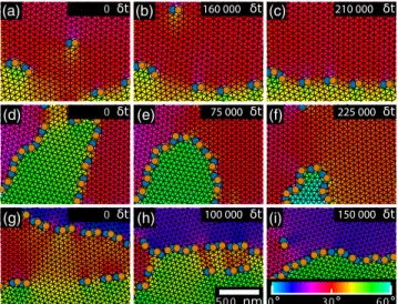
Observations of the boundaries ’ dynamics show a surge- like rearrangement of Skyrmion clusters changing their affiliation to an individual domain between frames. Row shifts and small rotating groups of Skyrmions can be seen as mechanisms of affiliation change. The Skyrmion number during these fluctuations is conserved with an accuracy of 1 in the analyzable image sections, supporting the picture of single topological particles that rearrange. This strongly hints at topological charge conservation during the rear- rangement processes.
The temporal evolution of the misorientation angle in Fig. 3 demonstrates the influence of the electron beam on two domains of the lattice. To visualize their dynamics, we FIG. 2. Defect densities along the grain boundaries relative to the misorientation angle evaluated manually and by an algorithm.
Also shown are values from Monte Carlo (MC) simulations and a
fit formula for symmetric low angle grain boundaries. (Inset) An
exemplary MC simulation for a tilt angle of Δθ ¼ 16 °.
recorded a 170-s-long movie using a frame rate of 30 frames = s. The sequence shown in the movie in the Supplemental Material [39] ranges from about 20 to 30 s.
The left and right parts of Fig. 3(c) show the two angles of the rotating domains from 20 to 40 s and from 155 to 170 s, respectively. The angles θ
1and θ
2can consistently be obtained either from the real-space images or from its Fourier transform; see Figs. 3(a) and 3(b). The evaluation of the first sequence reveals a fast rotation of one lattice (red) while the other (green) rotates much slower. It captures four full passes through all possible relative domain angles. For vanishing relative orientations (time spans i, iii, and v) the domain wall dissolves and a unified lattice is obtained; i.e., there is no grain boundary or only single defects visible in the field of view.
The second sequence shows a different process. At first, both grains rotate, with almost the same velocities keeping the misorientation angle constant (vi). Next, one grain stops rotating, leading to an increase of the net misorientation angle (vii). Before the maximum misorientation of Δθ ¼ 30 ° is reached, the other grain also stops (viii). During time span (ix), the inverse process of (vii) occurs, effectively reducing the misorientation angle. Then both grains stop (x) before one grain starts to move again (xi).
Note that the rotation direction during these processes remains mainly fixed in a counterclockwise direction, in accordance with the findings of Ref. [45]. However, slight deviations of this strict sense of rotation are observed for instance in region (vii), which we verified by raw data. This rotation in the opposite direction can be interpreted as gearwheel rotation of both lattices. The relative angular
speed varies from 0 ° = s to 15 ° = s. The differing behavior of the two sequences indicates that the effective rotational torques are substantially larger during the first sequence compared to the second sequence. As the temperature gradients are expected to be approximately constant in time, this arises very likely from changes in the size of the domains, and therefore in the total effective forces at the domain boundary. Indeed, indicated by a tilt of the orientation of the grain boundary, the relative domain sizes changed between the two sequences.
The topological protection of Skyrmions, the associated approximate conservation of Skyrmion number observed in our experiment, and the dominance of 5 – 7 defects suggest that Skyrmions should be viewed as discrete particles even in lattice textures. To corroborate this picture, we have performed simulations of large rotating Skyrmion lattices and track the motion of ∼35 000 Skyrmions treated as individual particles [48] arranged on a disk; see the Supplemental Material [39]. Even for this simplified approach, it is not possible to simulate directly the experimentally relevant time scales of tens of seconds, which is a factor of 10
10larger than the microscopic time scale for typical excitations of the Skyrmion lattice [49].
Remarkably, we are, however, able to reproduce qualita- tively the experimentally observed dynamics using current densities much larger than in the experiment.
Under the shear stress arising from the current pattern, domains characterized by different rotational angles form.
Most importantly, the simulations show the dynamical formation of domain walls consisting of 5 – 7 defects similar to our experimental observations; see Figs. 1(g) and 4.
20 25 30 35 155 160 165
0 20 40 60
θ1/2(deg)
Time (s)
i ii iii iv v
vi vii viii ix x
θ1 θ2 θ1
θ2
(a) (b)
(c)
xi Δθ=18° 18 K 48 mT 300 nm
FIG. 3. Temporal evolution of the angles θ
1and θ
2of the grains relative to a fixed axis. (a) The two grains and the measured angles. The circular arrows represent the rotational direction.
(b) A Fourier transformation of the data, where θ
1and θ
2are also present. (c) Two sequences in the temporal evolution of θ
1and θ
2. In the first sequence, one grain rotates faster than the other, going four times through the full range of misorientation. In the second sequence, variations of individual rotational speeds lead to an increase and a decrease of misorientation.
(a) (b) (c)
(d) (e) (f)
(g) (h) (i)