Staging optics considerations for a plasma wake fi eld acceleration linear collider
C.A. Lindstrøm
a,b,n, E. Adli
a,b, J.M. Allen
b, J.P. Delahaye
b, M.J. Hogan
b, C. Joshi
d, P. Muggli
c, T.O. Raubenheimer
b, V. Yakimenko
baDepartment of Physics, University of Oslo, Oslo 0316, Norway
bSLAC National Accelerator Laboratory, Menlo Park, CA 94025, USA
cMax Planck Institute for Physics, 80805 Munich, Germany
dDepartment of Electrical Engineering, UCLA, Los Angeles, CA 90095, USA
a r t i c l e i n f o
Keywords:
PWFA Staging
Emittance preservation Beam optics Linear collider
a b s t r a c t
Plasma wakefield acceleration offers acceleration gradients of several GeV/m, ideal for a next-generation linear collider. The beam optics requirements between plasma cells include injection and extraction of drive beams, matching the main beam beta functions into the next cell, canceling dispersion as well as constraining bunch lengthening and chromaticity. To maintain a high effective acceleration gradient, this must be accomplished in the shortest distance possible. A working example is presented, using novel methods to correct chromaticity, as well as scaling laws for a high energy regime.
&2016 Elsevier B.V. All rights reserved.
1. Introduction
A demand for TeV-scale electron–positron colliders has resul- ted in linear collider design studies which, if built, will be tens of kilometers long and cost billions of dollars. This has motivated an interest in cheaper and more compact accelerator technologies seeking to provide higher acceleration gradients.
Plasma wake
field acceleration (PWFA) is one of several new concepts, in which two consecutive charged particle beams are sent through a plasma, quickly and ef
ficiently transferring energy from one beam (the drive beam) to the other (the main beam).
These beams need to be very small, both transversely and long- itudinally, in order to excite a sufficiently large electric
field (thewakefield) to form an accelerating cavity in the plasma.
In order for the main beam to reach energies signi
ficantly higher than that of the drive beam, this process must be repeated in multiple stages. The plasma cells must be separated by beam optics which swaps out the depleted drive beam and focuses the diverging main beam back into the next cell. Since a shorter optics section gives a higher effective acceleration gradient, it is impor- tant to minimize its length.
2. Requirements
A linear collider requires very low emittance beams to reach the luminosity target. In order to preserve these emittances, all the way to the interaction point, a number of requirements must be met by the optics section between plasma cells. The goal is to
findthe shortest lattice which satisfy all these requirements.
We will assume beam and plasma parameters as defined in the PWFA linear collider study [1], where plasma cells operate in the non-linear blowout regime [2]. The main beam has an rms energy spread σ
Earound 1%, a bunch length of σ
z¼20 μ m, and normal- ized emittances of ϵ
N;x¼10 μ m and ϵ
N;y¼35 nm. The drive beam has energy E
d¼25 GeV, and the plasma has an electron density of n
p¼2
"10
16cm
#3, providing a gain of Δ E
¼25 GeV per cell. The emittance budget requires each stage to preserve emittance to the 1%-level.
2.1. Drive beam injection and extraction
Injecting the drive beam only a few 100 μ m in front of the main beam is too short for any kicker. However, dipoles can be used to combine and separate the two beams by utilizing their difference in energy.
2.2. Beta matching
The plasma cavity formed by the drive beam has strong linear focusing forces. If the β -function of the main beam is not properly Contents lists available at ScienceDirect
journal homepage:www.elsevier.com/locate/nima
Nuclear Instruments and Methods in Physics Research A
http://dx.doi.org/10.1016/j.nima.2015.12.065 0168-9002/&2016 Elsevier B.V. All rights reserved.
nCorresponding author.
E-mail address:c.a.lindstrom@fys.uio.no(C.A. Lindstrøm).
matched [2], the beam envelope will oscillate and the projected emittance increases. The Twiss [3] matching condition at the plasma cell is
β
x¼β
y¼β
mat¼ffiffiffiffiffiffi
2 γ
p
k
p ; ð1
Þα
x¼α
y¼0;
ð2Þwhere k
pis the plasma wavenumber and γ is the Lorentz factor. For our parameters, β
mat¼2:3 cm at 100 GeV.
2.3. Dispersion cancellation
The drive beam injection/extraction dipoles also disperse the main beam, due to its energy spread. Very small emittances require cancellation of dispersion:
D
x¼D
0x¼0;
ð3Þwhere D
xis the
first-order dispersion. Higher order dispersions may also require cancellation to avoid emittance growth.
2.4. Isochronicity
The dipoles form a chicane with a non-zero longitudinal dis- persion R
56. This leads to bunch lengthening or compression, which alters beam loading and the energy spread might increase.
To avoid this we require R
56⪡σ
zσ
E; ð4Þwhich is O
ð1 mmÞfor our parameters.
2.5. Chromaticity cancellation
Placing quadrupoles immediately before and after the plasma will focus the drive and main beams differently due to their energy difference, hence injection/extraction dipoles should be placed between the plasma and quadrupoles. However, this allows tightly focused main beams to diverge significantly after exiting the plasma, resulting in a large chromatic amplitude W. Since emit- tance growth from chromaticity is given by Δ ϵ
=ϵ
0¼1=
2W
2σ
2EþO
ðσ
4EÞ, we requireW
x¼W
y¼0;
ð5Þin which case the σ
4E-term will dominate chromatic emittance growth.
3. Drive beam injection and extraction 3.1. Symmetry between injection and extraction
After plasma interaction, particles in the rear of the drive beam will have lost a signi
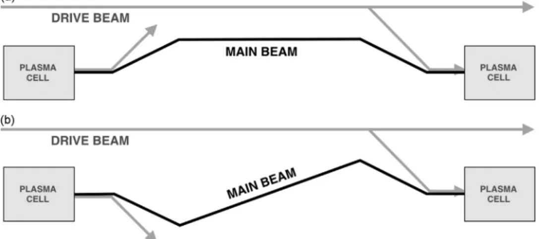
ficant fraction of their energy, but those in the front will remain at the injected energy. We assume that injection and extraction may be treated as inverse processes using the same optics, but in reverse order. This enforces either a mirror sym- metric (C) or rotationally (S) symmetric chicane (Fig. 1). The C- chicane has less total bending, producing less synchrotron radia- tion, whereas the S-chicane places injection and extraction on opposite sides, freeing up space for beam dumps and diverting radiation away from drive beam distribution and injection systems.
3.2. Injection/extraction dipole length
In order to reduce chromaticity, the distance to the
firstquadrupole should be minimized. The two beams will separate in the dipole by a distance
Δ x
¼1 2 l
2dBce 1
E
d#1 E
m" #
; ð6Þ
where l
dis the dipole length, B is the dipole magnetic
fieldstrength, and E
mis the main beam energy.
A defocusing quadrupole placed next to the dipole can be used to further separate the beams, hence shortening the necessary dipole length. However, it also focuses the drive beam and leads to larger dispersion. Injector/extractor design has not been studied in detail in this work.
3.3. Dispersion cancellation
Although C and S-chicanes intrinsically cancel dispersion, they do not in the presence of quadrupoles. This can be corrected by either appropriately matching quadrupoles or by introducing extra dipoles. However, quadrupole dispersion matching is not inde- pendent of beta and chromaticity matching, further complicating their simultaneous matching. Adding extra dipoles allows disper- sion cancellation independently of quadrupole matching.
Using a mirror symmetric quadrupole lattice, a single extra dipole per side is necessary, satisfying D
0x¼0 for C-chicanes or D
x¼0 for S-chicanes at the point of symmetry.Fig. 1. Symmetric layouts for injection/extraction dipoles. A mirror symmetric C-chicane is shown in (a), and a rotationally symmetric S-chicane is shown in (b).
3.4. R
56correction
The longitudinal dispersion R
56is given by [4]
R
56¼ ZD
xðs
Þρ
ðs
Þds;
ð7Þwhere ρ is the bending radius, indicating that the longitudinal dispersion can be decreased by placing dipoles in regions of low D
x, and canceled by introducing new dipoles with opposing R
56.
4. Main beam focusing and emittance preservation 4.1. Beta matching
Symmetry dictates that quadrupoles must form either a long- itudinally mirror symmetric (same polarity) or anti-symmetric (opposite polarity) lattice. If both injection and extraction require assistive defocusing quadrupoles, the lattice cannot be anti- symmetric.
Matching α and β -functions in both planes requires in general four degrees of freedom; e.g. four quadrupoles. Only two degrees of freedom are required for symmetric lattices ( α
x¼α
y¼0 or
β
x¼β
y, α
x¼ #α
yat the symmetry point), which greatly simpli
fies matching.
Using plasma density ramps [5], which adiabatically relaxes the β -function, it may be possible to match to an order of magnitude larger β . This dramatically improves chromaticity (as W
'β
quads'1= β
mat) as well as dispersion tolerances.
4.2. Chromaticity correction
Chromaticity is conventionally corrected using sextupoles.
Although very effective, sextupoles require large dispersion and introduce non-linear terms whose cancellation result in more complex lattices. Since dispersion needs to stay constant with energy, dipoles must get longer or stronger, resulting in a poor synchrotron radiation scaling with main beam energy. Motivated by this, a novel method was developed to correct chromaticity using linear lattices only [6], giving both shorter lattices and a better energy scaling.
5. Working example
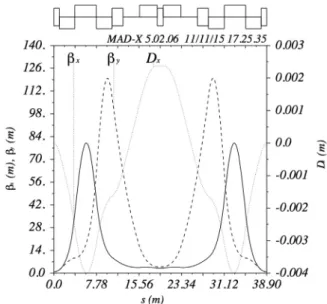
A working example for a high main beam energy of 500 GeV is shown in Fig. 2; a 39 m long C-chicane with 8 quadrupoles and 5 dipoles. This example assumes an energy spread of 0.5%, a 1 m injection/extraction dipole with
field strength 1 T, quadrupole
field gradients 95 T/m, and a plasma density ramp β -magni
fication of 15, giving an effective β
mat¼79 cm. Note that this is neither a general nor an optimized solution.
Particle tracking in Elegant [7] (Fig. 3), shows that emittance growth due to chromaticity is just 0.03% and 0.04% in x and y respectively, and the bunch length is preserved with R
56¼1:2 μ m.
Emittance growth in x from second-order dispersion is 2%. How- ever, at 1% energy spread, this emittance growth is 40%. In addi- tion, this problem gets worse at lower energies as dispersion increases, indicating that second-order dispersion needs to be actively canceled to achieve a higher energy acceptance. This will be addressed in further work.
6. Scaling laws
Since the drive beam energy stays constant, dipoles will bend the main beam less at higher energies. In addition, quadrupoles
must increase in length to still focus the main beam. We can identify two regimes, where E
dand E
mare the drive and main beam energies respectively:
1. Low energy
ðO
ðE
mÞ ¼O
ðE
dÞÞ: dominated by relatively strong dipoles.
2. High energy
ðE
m⪢E
dÞ: dipoles are weak and quadrupoles dom-inate the lattice.
6.1. Low energy regime
Dipoles produce large dispersion, demanding higher order cancellation. In addition, the length of injection/extraction dipoles is larger relative to β
mat, which requires chromaticity to also be canceled to higher order. This results in complex lattices custom made for each energy, with no clear scaling. In this case, with large dispersions and low energies, a solution using sextupoles may be favorable.
6.2. High energy regime
Assuming a constant quadrupole
filling factor, where allquadrupoles operate at maximum
field gradient, the lattice lengthscales as
pffiffiffiγ , where γ is the main beam Lorentz factor. Since also
β
matscales as
pffiffiffiγ , the β -pro
file scales with energy without chan- ging shape. Hence the same scaled lattice can be used for all (high) energies. Scaling laws are listed in Table 1.
Two options exist for scaling dipole lengths: constant length (l
d¼const, B
¼const), or constant
filling factor (l
d'pffiffiffiγ , B
'1=
pffiffiffiγ ).
Based on energy loss from synchrotron radiation W
SR'P
SRl
d'γ
2B
2l
d, the latter is preferable (W
SR'γ
1:5compared to W
SR'γ
2).
Emittance growth scales as σ
4E(if W
¼0), strongly encouraginglower energy spreads. Moreover, increasing the plasma density ramp magnification M
pdror the quadrupole
field gradientg
maxsuppresses emittance growth roughly as 1=M
3pdrand 1=g
1:5maxand shortens the total lattice length by 1=
pffiffiffiffiffiffiffiffiffiffig
max.
It is worth noting that laser wakefield acceleration (LWFA) operates in the
“high energy regime”at any energy, as laser injection/extraction does not require dipoles.
Fig. 2. Working example for 500 GeV, where 5 dipoles and 8 quadrupoles form a 39 m long C-chicane. Chromaticity is canceled by a linear lattice without sextu- poles, however an uncorrected second-order dispersion leads to a 2% emittance growth.
7. Further work
Further work includes
finding emittance preserving lattices atlower energies by considering second-order dispersion and chro- maticity cancellation, incorporating the inherent chromaticity of plasma channels
ðW
¼∂β
=∂δ
=β
¼1=2Þ into the linear lattice chromaticity correction, and studying the use of a positive R
56combined with the energy chirp in the plasma cavity in order to reduce the energy spread of the main beam.
8. Conclusions
The optics section between plasma cells in a staged PWFA linear accelerator needs to extract and inject drive beams using bending magnets, which sets stringent requirements on dispersion and R
56cancellation. Focusing of the highly diverging main beam leads to large chromaticity, which must be canceled to avoid emittance growth. Based on these constraints, using the symmetry of the system and a linear lattice without sextupoles for chroma- ticity correction, a high energy solution was found that meets these requirements. Scaling laws were found, which allow solu- tions to be scaled to very high main beam energies, however low energies will require higher order cancellation of dispersion and chromaticity for suf
ficient energy acceptance.
Acknowledgements
This work is supported by the Research Council of Norway.
References
[1] E. Adli, et al., A Beam Driven Plasma-Wakefield Linear Collider: From Higgs Factory to Multi-TeV,Electronic Proceedings of the Snowmass 2013,arXiv:1308.
1145v2, 2013.
Fig. 3.Phase space inx(upper) andy(lower) for initial (left) andfinal beam (right) of the 0.5% rms energy spread example inSection 5, tracked in Elegant[7]using 1:5"106 particles. Emittance is well-preserved, however thefinalx-phase space (upper right) shows a small 2% emittance growth due to uncorrected second-order dispersion.
Table 1
Energy scaling laws for the high energy regimeðEm⪢EdÞ. The same lattice is used for all energies, by scaling lengths aspffiffiffiγ, whereγis the main beam Lorentz factor.
Variable Symbol Energy scaling
Lattice length L pffiffiffiγ
Dipole, quad. length ld,lq pffiffiffiγ,pffiffiffiγ
β-functions β pffiffiffiγ
Spot size σx 1=p4ffiffiffiγ
Dispersion Dx 1=pffiffiffiγ
Isochronicity R56 1=pffiffiffiγ
Chromatic amplitude W Const.
Emittance growth Δϵ
ϵ0
Const.
Quad.field gradient gmax Const.
SR power, energy loss PSR,WSR γ,γ1:5
[2] J.B. Rosenzweig, et al., Physical Review A44 R6189(R), 1991.
[3] E.D. Courant and H.S. Snyder, Annals of Physics 1958.
[4] K. Wille, The Physics of Particle Accelerators (pp. 76-77), Oxford, UK: Oxford University Press, 2000.
[5] X. Xu, et al.,arXiv:1411.4386v2, 2015.
[6] C.A. Lindstrøm, E. Adli, to be submitted.
[7] M. Borland, ANL Advanced Photon Source Report No. LS-287, 2000.
![Fig. 3. Phase space in x (upper) and y (lower) for initial (left) and final beam (right) of the 0.5% rms energy spread example in Section 5, tracked in Elegant [7] using 1:5 " 10 6 particles](https://thumb-eu.123doks.com/thumbv2/1library_info/4011335.1541154/4.892.117.768.86.628/phase-initial-final-example-section-tracked-elegant-particles.webp)
