Pyrolysis/Gasification
Innovative Application Methods of Slags
from High-Temperature-Gasifying-and-Direct-Melting System
Masato Katafuchi, Stanislaw Stryczek, Radoslaw Mroz and Wojciech Wons
1. Overview of gasifying and melting system ...446
2. Test methods of slag ...448
2.1. Chemical analysis – XRF method ...448
2.2. Phase composition – XRD analysis ...449
2.3. Additional phase composition analysis – DTA analysis ...449
2.4. Thermal evolutions of slag – High-temperature microscopy ...449
2.5. Susceptibility to milling (grindability) ...449
2.6. Leaching/elution tests ...450
2.7. Natural radioactivity ...450
3. General characteristic of slag ...450
4. Characteristic of slag for innovative application ...451
5. Environmental safety of slag in regard of practical application ...454
6. Conclusions ...455
7. References ...456 JFE High-Temperature Gasifying and Direct Melting Furnace System (hereinafter Gasifying and Melting System) was developed to treat any kind of wastes and to con- tribute to energy and material recovery. Gasifying and Melting System was developed by integrating company’s original technologies for the iron-making blast furnace and fluidized bed for incineration plants, which the company cultivated over many years.
The company’s advanced technologies in these two different fields were combined and integrated into the unique Gasifying and Melting System. This system is a proven technology that realizes high performance, as outlined below [1, 3, 6, 7].
• Non-combustibles in wastes are converted to nontoxic, completely safe and en- vironmental friendly vitrified slag that can be recycled as a valuable material. In Japanese standards, called JIS standards, exist norms for use of molten slag as road and concrete raw materials. The slags from Gasifying and Melting system satisfy those norms and therefore they are widely used in those applications.
Pyrolysis/Gasification
• Environmentally-safe treatment of various kinds of wastes is possible, including re- fuse derived fuel, sewage sludge, industrial wastes, incineration residues, excavated wastes and/or asbestos, in addition to municipal solid waste.
• Combustibles in wastes are converted into raw synthesis gas.
• Highly efficient power generation, ηel = 30 percent, is realized.
From the point of view of material recovery, the molten slag is widely known as a useful material. In the European market bottom ash generated from waste incinerator is often recycled as road base material etc. Until present, the molten slag was regarded rather as low-price and low-added value alternative material similarly to bottom ash.
However, theses slags from Gasifying and Melting System shouldn’t be indicated only as a useful waste to the well-known undemanding applications, but first of all as a va- luable resource for the new potential innovative and environmentally friendly fields of applications. Presented in the article results of various analysis and measurements are focused on the two directions. First, to determine potential areas of consumption of mentioned slags in selected technologies, and second to verify environmental friendly properties of analysed materials.
1. Overview of gasifying and melting system
The overall process flow of Gasifying and Melting Furnace is described in Figure 1 [2, 5].
Comparing to the other gasification technologies, this system is one of the most com- pact ones. It is because Gasifying and Melting Furnace combines both gasification and melting functions in a single furnace. Combustible content of waste is gasified in the high temperatures inside of the furnace. Non-combustibles in wastes are melted and turned into slag and metals for reuse.
Wastes are fed into the furnace with coke and limestone from top of the furnace. Coke plays a role as fire grates that keep flow path of gas and slag. Also it works as the heat source and prevents cool-down of slag.
Since inside of the furnace reduction atmosphere is kept, hazardous heavy metals are vaporized to the gaseous phase and ash content is converted to slag. The slag dischar- ged from furnace bottom is quenched in a water-granulation conveyor to produce granulated and environmentally safe slag and metals.
The raw synthesis gas discharged from the furnace is introduced into the secondary combustion chamber in front of the boiler. Then, the raw synthesis gas is combusted completely in this chamber.
Combustion air is supplied with an air blower located near the waste pit. To minimize odour spread outside of the plant, the air from waste pit is used as combustion air. Auto- matic Combustion Control (ACC) regulates the combustion airflow rate automatically.
Steam produced in the boiler is fed into the steam header via super heaters. All the steam is supplied to steam turbines and steam extractions from turbines are carried out to improve the power generation efficiency.
Pyrolysis/Gasification
RDF Storage silo 1
#2RDF sub hopper#1RDF sub hopper
#2RDF feede
r
#1RDF feede
r RDF weighing machine
Coke
Return ash
Limestone RDF & submaterial conveyor
Coke conveyor
RDF submaterial feeding conveyo
rCombustion air blowerElectric power generation Steam turbine
Electric generator Secondary combustion chamber (S.C.C.) Super heaterShot distributer
Exhaust gas recirculation fan Boiler
Compressed service air
Slaked lime an
d activated carbon
Bag filter Bag filter conveyor
Stack Steam gas heater DeNox reactorSteam
Induced draft fa
n
Fly ash storage tank Heavy metal stabilizer
No. 1 fly ash withdrawal conveyor
Fly ash conveyor Fly ash kneading machineRDF Submaterial Ash Slag Metal Flue gas
Oxygen and nitrogen Air and recirculate
d exhaust gas
Solidified fly ash bunker
1Return ash
Shot sorter
No. 1 economizer conveyor Shot stag
e tank
No. 2 economizer conveyor
No. 3 economizer conveyor
No. 1 boiler conveyor No. 2 boiler conveyor
Shot transfer blower conveyor Return ash conveyorNo. 2 S.C.C. collecting conveyor No. 1 S.C.C. collecting conveyor metal yardSlag yard
Slag crusher
Magnetic SeparatorWater-granulation conveyor
Main tuyere
Secondary tuyere
Third tuyereThird tuyere blower Secondary tuyere blower Main tuyere blower
Steam air heater Steam Oxygen generator Nitrogen generator Figure 1:Overall process flow of gasifying and melting system
Pyrolysis/Gasification
Moreover, the working load for the operator to discharge slag and metals is significantly decreased by adoption of original slag continuous discharging system.
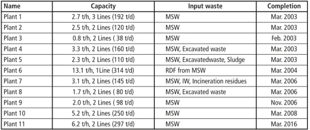
The plant construction record of Gasifying and Melting System is shown in Table 1.
Our Gasifying and Melting System is applied in 11 plants (22 lines) in Japan since 2003.
The plants have been operated without any major troubles and according to designed values.
Table 1: Construction record of gasifying and melting system
Name Capacity Input waste Completion
Plant 1 2.7 t/h, 3 Lines (192 t/d) MSW Mar. 2003
Plant 2 2.5 t/h, 2 Lines (120 t/d) MSW Mar. 2003
Plant 3 0.8 t/h, 2 Lines ( 38 t/d) MSW Feb. 2003
Plant 4 3.3 t/h, 2 Lines (160 t/d) MSW, Excavated waste Mar. 2003 Plant 5 2.3 t/h, 2 Lines (110 t/d) MSW, Excavatedwaste, Sludge Mar. 2003
Plant 6 13.1 t/h, 1Line (314 t/d) RDF from MSW Mar. 2004
Plant 7 3.1 t/h, 2 Lines (145 t/d) MSW, IW, Incineration residues Mar. 2006 Plant 8 1.7 t/h, 2 Lines ( 80 t/d) MSW, Excavated waste Mar. 2006
Plant 9 2.0 t/h, 2 Lines ( 98 t/d) MSW Nov. 2006
Plant 10 5.2 t/h, 2 Lines (250 t/d) MSW Mar. 2008
Plant 11 6.2 t/h, 2 Lines (297 t/d) MSW Mar. 2016
MSW – municipal solid waste, RDF – refuse derived fuel, IW – industrial waste
2. Test methods of slag
For laboratory test were gathered three samples of slag from two different operating reference plants in Japan. Two of the samples are coming from plant X (marked as samples A and B), which is treating municipal solid waste of approximately 9 MJ/kg of calorific value. Those samples were picked up on different dates (one month difference).
One other sample is coming from plant Y (marked as sample C), which is treating municipal solid waste of approximately 7 MJ/kg of calorific value.
Following test methods were used for comprehensive slag analysis.
2.1. Chemical analysis – XRF method
X-ray Fluorescence Analysis (XRF) was conducted to clarify the chemical composition of analysed slags. The chemical analysis of all slags was performed with WD XRF spectrometer Axios mAX company. Using the XRF spectrometer, it is possible not only determination of the elemental composition in the range almost the whole of the periodic table (from boron to uranium), but also to quantify the percentage weight proportion of each element in the sample. Samples of slags for XRF analysis were pre- pared in the form of powders with a particle size of under 0.063 mm.
Pyrolysis/Gasification
2.2. Phase composition – XRD analysis
To identify the phase composition of slags PANalytical X’Pert Pro X-ray diffractome- ter, with Cu Ka1 (λ = 1.5406Å) with a primary curved germanium monochromator
Parameter Unit Value Range 2θ degree from 3 to 90 Step size 2θ degree 0.017 Time per step ms 256.905
Table 2: Parameters of the measurement (Johansson type) was used. Samples of slags for XRD analysis, the same like in case XRF analysis were prepared in the form of pow- ders with a particle size of under 0.063 mm.
Measurements were carried out with the following parameters (Table 2).
2.3. Additional phase composition analysis – DTA analysis
To clarify translation and crystallization processes with the heating in analysed mate- rials, DTA measurement was conducted. DTA measurement with thermogravimetry was performed in a STA 449F3 Jupiter Netzsch apparatus. The study was conducted in an atmosphere of synthetic air with a flow of 40 ml/min. The rate of heating was 15 °C/min. Samples were milled to a grain size below 0.06 mm and weighted in range from 85 to 95 mg.
2.4. Thermal evolutions of slag – High-temperature microscopy
High-temperature microscopy is one of the thermal methods of analysis in which the changes in the shape of the sample are measured in the given heating range. During the measurement were determined so-called characteristic temperatures among which, the most relevant are:
• Beginning of the Sintering (first shrinkage associated with sintering),
• Maximum of the Sintering (shrinkage maximum of sintering without deformation),
• Softening Point (first deformation of sample),
• Maximum of Thermal Expands (maximum area of sample, which is caused pyro- plastic behavior),
• The melting point (sample is hemispherical).
The measurements were performed in a high-temperature microscope (Hesse Instru- ments). For tests were prepared battle-shape samples with dimensions d = h = 3 mm from ground (<0.063 mm) samples of slag. The measurement was carried out in air atmosphere at the constant heating rate of 10 °C/min up to temperature 1,300 °C.
2.5. Susceptibility to milling (grindability)
The milling test was conducted to confirm how long it needs to be milled to satisfy the requirement of specific surface for some designated application [4]. Slags were ground in a typical laboratory mill, with a capacity 80 dm3. Optimal ball/cylpeps charge
Pyrolysis/Gasification
distribution has been specially adapted for grinding cement binders, including common raw materials used for production of common cements such as slag, limestone, etc.
Milling was carried out periodically with short intervals for preparation of samples to determination of their specific surface area measured with Blaine’a methods until the specific surface area of milled slags reach level 4,000 cm2/g.
2.6. Leaching/elution tests
Relatively important issue for management of waste materials is water elution of sub- stances, mainly heavy metals. Water elusion was conducted on slags in unground form.
Preparation of samples was made according to requirements of EN 12457-2:2006 and it consisted of 24-hour elution of analysed material in 1:10 proportion with distilled water. After 24 hours the suspensions were filtered on a cotton filter. Obtained clear solution was acidulated in order to avoid precipitation of hydroxides. Concentration of cations in solution was tested in mass spectrometer with inductively coupled plasma (ICP-MS) using ELAN 6100 produced by Perkin Elmer.
2.7. Natural radioactivity
The slag was performed on the possible radioactivity contamination. The sample was analysed by the gamma spectrometric method in a low-background counting facility.
3. General characteristic of slag
Below are presented the results of testing showing the general characteristics of slag.
Those characteristics indicate although potential directions of innovative application fields of mentioned slag.
Chemical analysis – XRF
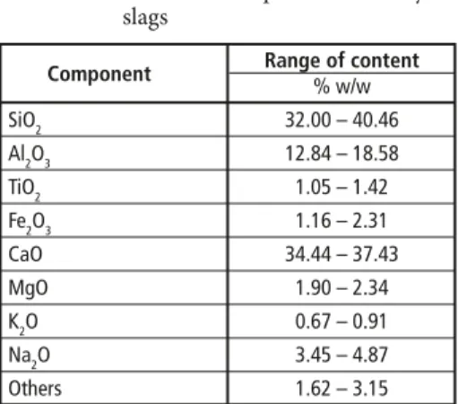
The measurement results are presented in Table 3.
Component Range of content
% w/w
SiO2 32.00 – 40.46
Al2O3 12.84 – 18.58
TiO2 1.05 – 1.42
Fe2O3 1.16 – 2.31
CaO 34.44 – 37.43
MgO 1.90 – 2.34
K2O 0.67 – 0.91
Na2O 3.45 – 4.87
Others 1.62 – 3.15
Table 3: Chemical composition of analysed
slags Investigated slags contain sufficient
enough amount of sodium oxide. Using those slags as an additive to ceramic ma- terials generate a large amount of liquid phase, which intensifies the sintering of ceramic materials.
Additionally, due to the high content of the glassy phases characterized as alumina-silicate with high participation of calcium oxide, analysed slags should be considered as interesting component of special mineral binders [4].
Pyrolysis/Gasification
Phase composition – XRD analysis The results of XRD measurement are presented in Figure 2.
The following conclusions can be drawn from the XRD analysis:
1. Absence of clear peaks and raised background in specific angle bands in the XRD diffraction patterns confirm the amorphous/glassy nature of the tested materials.
2. Raised background appears on XRD patterns of all analysed slags. Background raising in the analysed patterns presented bimodal distribution: in range 6 – 17° 2θ
and 23 – 37° 2θ. The reason of this duality is the presence in the tested materials two types of the glassy phase. Probably: silicate glass (in the range 23 – 37° 2θ) and silica-alumina glass containing a significant amount of alkali oxide (in the range 6 – 17° 2θ).
3. Detailed analysis of the diffraction patterns shows that the analysed slags besides the amorphous component may content small quantities of the crystalline minerals.
In addition, to confirm the results of XRD analysis, FT-IR spectra analysis was also performed on the slags. Additionally made FT-IR analysis confirmed aluminosilicate glassy nature of analysed slags.
Intensity 1,400 1,200 1,000 800 600 400 200 0
C B A
2θ CuKα
3 8 13 18 23 29 34 39 44 49 54 59 64 69 74 80 85 90 Figure 2:
XRD patterns of analysed materials
4. Characteristic of slag for innovative application
For the application of slags in building ceramics, it was useful to perform and check the results of DTA analysis and thermal evolutions of the material.
Results of above mentioned tests are described as below.
Pyrolysis/Gasification
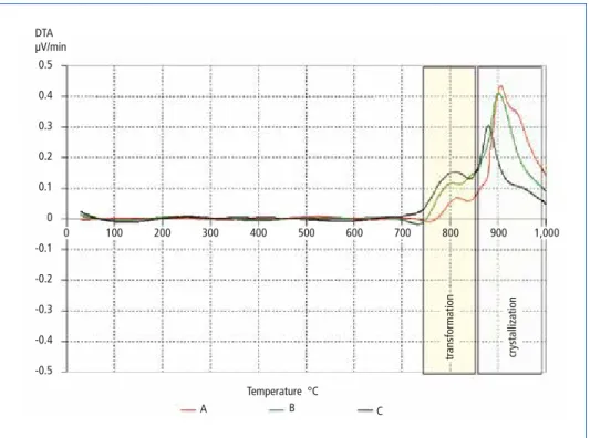
Additional phase composition analysis – DTA analysis Figure 3 presents the results of measurements.
Performed DTA analysis of slags allows to formulate the following conclusions:
1. Glassy phase present in the analysed slags is subjected to the exothermic transfor- mation (pseudo-arrangement of glassy domains) in the range 730 to 850 °C.
2. Above 850 °C the glassy phase of the slags is subjected to partial crystallization (de-vitrification). The peaks corresponding to these reactions in the case of slag A is bimodal, what indicating crystallization at least two new phases.
DTA µV/min
0.5 0.4 0.3 0.2 0.1 0 -0.1 -0.2 -0.3 -0.4 -0.5
Temperature °C
A B C
0 100 200 300 400 500 600 700 800 900
transformation crystallization
1,000
Figure 3: DTA curves of analysed slags
Thermal evolutions of slag – High-temperature microscopy
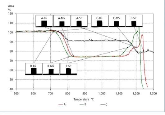
Figure 4 and Table 5 show comparison of surface shape changes of all analysed samples during high temperature heating.
The following conclusions can be drawn from the high-temperature microscopic observations:
The most intensive changes and at the lowest sintering temperature represent slags from sample A and B. Also, what is very important, they have a wide interval of tem- peratures in which can safely be sintered. Sintering range begins in temperatures of approximately 700 to 800 °C, and extends up to approximately 1,200 °C, what gives the span of more than 400 °C.
Pyrolysis/Gasification
Slag is potentially valuable addition to the ceramic materials. It can be used as flux in the sintering processes.
Slag C is characterized by little lower sintering but it have comparable interval of tem- peratures in which can safely be sintered, what does not preclude its use as a flux in sintering processes in building materials production.
Area
% 120 110 100 90 80 70 60 50 40
A-BS A-MS A-SP C-BS C-MS C-SP
B-BS B-MS B-SP
500 600 700 800 900 1,000 1,100 1,200 1,300
Temperature °C
A B C
Figure 4: Area curves changes of slag samples – juxtaposition
Table 4: Parameters of measurement
Furnace Parameter BS MS SP MTE MP
Sample A Temperature °C 735 840 1,220 1,235 1243
Area % 101.3 73.9 88.4 97.9 90.8
Sample B Temperature °C 720 820 1,150 1,215 1,223
Area % 100.7 74.1 87.7 107.9 77.4
Sample C Temperature °C 740 1,215 1,235 1,270 –
Area % 101.1 77.8 78.3 81.8 –
BS – beginning of the sintering, MS – maximum of the sintering, SP – soften point, MTE – maximum of thermal expands, MP – melting point
Susceptibility to milling (grindability) This test was performed to determine the time of milling sufficient to achieve the specific surface value required for application of slags into special mineral binders or for common cements (usually about/approximately 4,000 cm2/g). For application into building ceramics as fluxes the requirement is approximately 1,000 cm2/g.
Pyrolysis/Gasification
The results of slags milling times are sum- marized in Table 5.
As can be seen from Table 5, the slag’s required milling time to achieve the re- quired specific surface value is quite short.
Sample code A B C
Time min Specific surface cm2/g
30 1,700 1,700 1,650
60 2,750 2,700 2,500
90 3,450 3,450 3,150
100 3,700 3,650 3,350
110 3,900 3,850 3,500
120 3,950 3,950 3,650
125 – 4,000 3,750
130 – – 3,850
135 – – 3,900
140 – – 3,900
145 – – 3,950
Table 5: Results of milling tests
5. Environmental safety of slag in regard of practical application
As a conclusion of above tests results, besides well-known undemanding applications, we were able to point out, among others, following promising directions of innovative applications of slags:
• Ceramic materials including building ceramics
• High strenght special mineral binders.
To confirm health and environmental safety of slag for above application, the slags were analysed for leaching/elution test and natural radioactivity tests results. Those tests results are described as below.
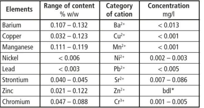
Leaching/elution tests
Test results are presented in Table 6.
Elements Range of content Category Concentration
% w/w of cation mg/l
Barium 0.107 – 0.132 Ba2+ < 0.013 Copper 0.032 – 0.123 Cu2+ < 0.001 Manganese 0.111 – 0.119 Mn2+ < 0.001 Nickel < 0.006 Ni2+ 0.002 – 0.003
Lead < 0.003 Pb2+ < 0.005
Strontium 0.040 – 0.045 Sr2+ 0.007 – 0.086
Zinc 0.021 – 0.122 Zn2+ bdl*
Chromium 0.047 – 0.088 Cr3+ 0.001 – 0.005
* below the detection limit
Table 6:
Concentration of selected heavy metals in filtered solutions
Pyrolysis/Gasification
For better clarification of obtained results in table are presented results of XRF analysis (elements) in comparison to concentration of heavy metals (ions) in filtered solutions.
It can be concluded that in the analysed materials, the total content of heavy metals is negligible, and it should be underlined, that because of their vitreous nature, the elution of heavy metals is also insignificant.
Natural radioactivity The results of natural radioactivity of analysed slags are summarized in Table 7.
Natural radioactivity of the analysed materials does not exceed limits listed in Regulation of the Council of Ministers of the Republic of Poland of 2 January 2007 laying down maximum permitted levels of natural radioactivity of building materials (O.J. No 4 item 29). Those limits are listed below. The activity indicators of all analysed samples of slags in accordance with the appointed criteria should not exceed the following values:
• Not more than 10 percent over 1 for f1,
• Not more than 10 percent over 200 Bq/kg for f2,
if the materials will be used for the production of building materials used in buildings designed to people accommodation.
Table 7: Results of the possible radioactivity contamination of slags
Activity Activity Activity Activity
K-40 Ra-226 Th-228 index: f1* index: f2* Ra-226+ Ra-228
Bq/kg Bq/kg Bq/kg – Bq/kg Bq/kg
Sample 183 – 219 21 – 27 24 – 30 0.28 – 0.30 21 – 27 45 – 57
*f1 and f2 are defined as bellows,
f1 = SK 3000Bq/kg
SRa 300Bq/kg
STh 200Bq/kg
+ + (1)
f2 = SRa ≤ 240 Bq/kg (2)
where:
SK = K-40 concentration in Bq/kg SRa = Ra-226 concentration in Bq/kg STh = Th-228 concentration in Bq/kg
6. Conclusions
The slag from Gasifying and Melting System indicates special features, listed as follows:
• Slag is characterized by high vitrification.
Pyrolysis/Gasification
• Due to the high content of the glassy phases and sufficient enough amount of sodium oxide, analysed slags are very beneficial for the use in ceramics technology (as flux) and as a component of special binders (auto-activation of slag). Simultaneously slags satisfy Japanese JIS standards for use of the molten slag as road and concrete raw material.
• Also due to the high content of the calcium oxide in analysed slags, they could be considered as an interesting component of special mineral binders.
• The results of leaching/elution tests show a very low elution of heavy metals from slags and also very low result values of natural radioactivity, what mean that slags can be considered as a safe materials for wide range of building constructions.
• Slags are characterized by good susceptibility to milling, which means that cost of milling will be relatively low and using of special facilitate grinding agents will not be required.
7. References
[1] Akashi, T.; Tada, M.; Uchiyama, T.: Vitrification of Asbestos Wastes by JFE High-Temperature Gasifying and Direct Melting Plant. In: JFE technical report No. 25, February 2010, pp. 7-10 [2] Inada, T.; Matsudaira, T.; Ishizeki, K.: High-Efficiency RDF Power Plant by the HTGDM Process.
In: JFE technical report No. 6, December 2004, pp. 49-53
[3] Katafuchi, M.; Shinagawa, T.; Abuku, M.; Nagayama, S. (2015): High-Temperature Gasifying and Direct Melting System for Energy and Material Recovery from any Type of Wastes. In:
Thome-Kozmiensky, K. J.; Thiel, S. (ed.): Waste Management, Volume 5. Neurupin: TK Verlag Karl Thome-Kozmiensky, 2015, pp. 453-465
[4] Małolepszy, J.: The hydration and the properties of alkali activated slag cementitious materials.
Scientific Bulletins of Stanisław Staszic Academy of Mining and Metallurgy – Ceramics, Bulletin 53, AGH, Kraków, 1989
[5] Matsudaira, T.; Sudo, M.; Yamakawa, Y.: The JFE High-Temperature Gasifying and Direct Mel- ting Furnace. In: JFE technical report No. 3, July 2004, pp. 15-20
[6] Shinagawa, T.; Nagayama, S.; Yamamoto, H.; Suzuki, A.: High Efficiency Power Generation and Valuable Slag Production by High Temperature Gasifying and Direct Melting Furnace. Procee- dings Crete 2014, 4th International Conference Industrial and Hazardous Waste Management [7] Suzuki, A.; Nagayama, S.: High efficiency WtE power plant using High-Temperature Gasifying
and Direct Melting Furnace. Proceedings Sardinia 2011, Thirteenth International Waste Ma- nagement and Landfill Symposium
Bibliografische Information der Deutschen Nationalbibliothek Die Deutsche Nationalbibliothek verzeichnet diese Publikation in der Deutschen Nationalbibliografie; detaillierte bibliografische Daten sind im Internet über http://dnb.dnb.de abrufbar
Thomé-Kozmiensky, K. J.; Thiel, S. (Eds.): Waste Management, Volume 6 – Waste-to-Energy –
ISBN 978-3-944310-29-9 TK Verlag Karl Thomé-Kozmiensky
Copyright: Professor Dr.-Ing. habil. Dr. h. c. Karl J. Thomé-Kozmiensky All rights reserved
Publisher: TK Verlag Karl Thomé-Kozmiensky • Neuruppin 2016
Editorial office: Professor Dr.-Ing. habil. Dr. h. c. Karl J. Thomé-Kozmiensky,
Dr.-Ing. Stephanie Thiel, M. Sc. Elisabeth Thomé-Kozmiensky, Janin Burbott-Seidel und Claudia Naumann-Deppe
Layout: Sandra Peters, Anne Kuhlo, Janin Burbott-Seidel, Claudia Naumann-Deppe, Ginette Teske, Gabi Spiegel und Cordula Müller
Printing: Universal Medien GmbH, Munich
This work is protected by copyright. The rights founded by this, particularly those of translation, reprinting, lecturing, extraction of illustrations and tables, broadcasting, micro- filming or reproduction by other means and storing in a retrieval system, remain reserved, even for exploitation only of excerpts. Reproduction of this work or of part of this work, also in individual cases, is only permissible within the limits of the legal provisions of the copyright law of the Federal Republic of Germany from 9 September 1965 in the currently valid revision. There is a fundamental duty to pay for this. Infringements are subject to the penal provisions of the copyright law.
The repeating of commonly used names, trade names, goods descriptions etc. in this work does not permit, even without specific mention, the assumption that such names are to be considered free under the terms of the law concerning goods descriptions and trade mark protection and can thus be used by anyone.
Should reference be made in this work, directly or indirectly, to laws, regulations or guide- lines, e.g. DIN, VDI, VDE, VGB, or these are quoted from, then the publisher cannot ac- cept any guarantee for correctness, completeness or currency. It is recommended to refer to the complete regulations or guidelines in their currently valid versions if required for ones own work.