Graph Based Modeling and Implementation with EER/GRAL
J. Ebert, A. Winter, P. Dahm, A. Franzke, R. Suttenbach University of Koblenz, Institute for Software Technology, Rheinau 1,
D-56075 Koblenz, email: ebert@informatik.uni-koblenz.de
Abstract. This paper gives a cohesive approach to modeling and im- plementation with graphs. This approach uses extended entity relation- ship (EER) diagrams supplemented with theZ-like constraint language GRAL. Due to the foundation of EER/GRAL on Z a common formal basis exists. EER/GRAL descriptions give conceptual models which can be implemented in a seamless manner by ecient data structures using the GraLab graph library.
Descriptions of four medium size EER/GRAL-applications conclude the paper to demonstrate the usefulness of the approach in practice.
1 Introduction
Using graphs as a means for discussing problems, as a medium for formal rea- soning, or as a paradigm for data structures in software is folklore in today's computer science literature. But most of the dierent approaches that use graphs are not used in a coherent way.
There are dierent models in use based on undirected or directed graphs, with or without multiple edges or loops. Sometimes graph elements are typed or attributed, sometimes they are not. Mathematical graph theory usually deals only with graph structure [Har72], whereas computer science usually uses graphs where vertices are distinguishable [Meh84]. In applications, graphs are often used without a formal basis. This leads to problems when assertions about the models have to be proved. Furthermore, graphs are frequently implemented using non- graph-based repositories that do not match the conceptual graph model exactly.
In this paper, we present a coherent and consistent approach to using graphs in a seamless manner
{
as conceptual models,{
as formal mathematical structures, and{
as ecient data structureswithout any discontinuity between these three aspects.
The approach, which is called the EER/GRAL approach throughout this pa- per, is based on extended entity relationship descriptions (EER diagrams, sec- tion 3.1) which are annotated by formal integrity conditions (GRAL assertions, section 3.2) in order to speciy graphs, which are eciently implementable by an appropriate C++ library (GraLab, section 4). A very general class of graphs is used (TGraphs, section 2) as basis.
As opposed to [EF95], where the theoretical basis is explained, the aim of this paper is to give an introduction into the approach with emphasis on its practical applicability.
Each of the applications sketched in section 5 has been described by technical reports which are publically available1.
2 TGraphs
To make the approach as useful as possible a rather general kind of graphs has to be treated. TGraphs are used as the basic class of graphs. TGraphs are
{
directed, i.e. for each edge one has a start vertex and an end vertex,{
typed, i.e. vertices and edges are grouped into several distinct classes,{
attributed, i.e. vertices and edges may have associated attribute-value pairs to describe additional information (where the attributes depend on the type),{
andordered, i.e. the edges incident with a particular vertex have a persistent ordering.All these properties are, of course, only optional. If a certain application only needs undirected graphs without any type, attribute or ordering, the respective properties may also be ignored.
2.1 Formal Denition
TGraphs as mathematical objects are specied using theZ-notation [Spi92].
The basic elements of TGraphs are vertices and edges. With respect to a vertex an edge may have a direction, i.e. it may occur as an out-edge or as an in-edge. Graph elements may have a type and they may have attribute-value pairs associated.
ELEMENT ::=vertexhhNiijedgehhN ii VERTEX == ranvertex
EDGE== ranedge DIR::=injout [ID;VALUE] typeID==ID attrID==ID
attributeInstanceSet ==attrID!77 VALUE
Using these basic denitions the structure of a TGraph consists of its vertex set, its edge set and an incidence function, which associates to each vertex v the sequence of its incident edges together with their direction.
1 Most of them can also be found viahttp://www.uni-koblenz.de/ist.
TGraph V :FVERTEX E :FEDGE
:VERTEX !7 seq(EDGEDIR) type:ELEMENT !7 typeID
value:ELEMENT !7 attributeInstanceSet
2V !iseq(E DIR)
8e:E91v;w :V (e;in)2ran((v))^(e;out)2ran((w)) domtype=V[E
domvalue=V [E
This class of graphs is very general and allows object-based modeling of application domains in an unrestricted manner.
The formal denition of TGraphs by a Z-text admits an equally formal denition of all concepts described in this paper (e.g. the semantics of EER diagrams and GRAL) and gives the opportunity for reasoning about all kinds of properties of graphs in a common and powerful calculus.
2.2 Modeling using TGraphs
TGraphs can be used as formal models in all application areas that are subject to object-based modeling.
It is useful to adopt a general modeling philosophy for TGraph-based software development in order to exploit the full power of the approach. We propose to use the following rules ([EF95])
{
every identiable and relevant object is represented by exactly one vertex,{
every relationship between objects is represented by exactly one edge,{
similar objects and relationships are assigned a common type,{
informations on objects and relationships are stored in attribute instances that are assigned to the corresponding vertices and edges, and{
an ordering of relationships is expressed by edge order.Of course, these rules require some modeling decisions (e.g. to decide what can be viewed as \relevant"). They help to achieve an appropriate formal graph model in the modeling process. Some examples will be shown later in this paper.
3 Graph Classes
The set of possible TGraph models for a given application is usually a subset of the set of all TGraphs, at least if the application domain has some sensible structure. This leads to the task of dening classes of TGraphs in a formal manner.
Here we propose to use extended entity relationship descriptions (EER di- agrams) for this purpose. These diagrams may be annotated by additional re- strictions (GRAL assertions).
3.1 EER Diagrams
EER diagrams are able to denote information about graph classes in a straight- forward manner:
{
entity types denote vertex types,{
relationship types denote edge types,{
generalizations describe a vertex type hierarchy,{
incidences between relationship types and entity types describe restrictions on the incidence structure,{
attributes describe the attribute structure of vertices and edges, depending on their type, and{
higher-level modeling constructs like aggregation and grouping add addi- tional structural information.Example:
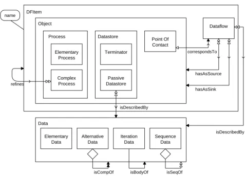
Fig. 1 shows the denition of a graph class DFD which gives the conceptual model of dataow diagrams, i.e. it contains the metamodel for a dataow lan- guage. The dataow metamodel is used to generate an editor for dataow dia- grams [Dru96] with the KOGGE-Generator, described in section 5.2.
Point Of Contact Elementary
Process
Complex Process Process
Terminator
Passive Datastore Datastore Object
Dataflow
hasAsSource
hasAsSink correspondsTo
isDescribedBy
isDescribedBy
isCompOf isBodyOf isSeqOf
Elementary Data
Alternative Data
Sequence Data Iteration
Data Data
DFItem
refines name
Fig.1.
EER diagram for dataow diagramsDataow diagrams describe procedural aspects through the main concepts Process, Datastore and Dataow. These concepts are modeled as vertex types, which may be specialized. E.g. the concept Process is subdivided into Complex Processes, which are rened by further dataow diagrams, and Elementary Processes. (Note, that specialization is depicted by inclusion of the respective rectangles of the vertex types, like in Venn diagrams.)
The relationships between these concepts are modeled using edge types. Each Dataow connects exactly two Objects, its source and its sink. Data stored in PassiveDatastoresor transported by Dataows is described as regular structures in a datadictionary.
The renement of ComplexProcesses by further DFItems is modeled using renes-edges. PointOfContact-vertices are used as surrogates for dataows in a
renement.
[CEW96] describes a complete formal semantics of EER diagrams in terms of the TGraph class which is specied by a given diagram. This is done by dening an appropriate TGraph for the EER diagram itself. The set SchemaGraph of those TGraphs which describe EER diagrams is the domain of the semantic function
graphSpecOf : SchemaGraph!GraphSpec
which assigns a graph class specication to every instance of SchemaGraph.
(This function is formally dened usingZ.)
For a given TGraph g 2SchemaGraph the result graphSpecOf (g) is a speci- cation of the set of instance TGraphs of the EER diagram described by g. The TGraph class corresponding to graphSpecTo(g) is the set of all graphs h, which fulll the specication. E.g., the TGraph class SchemaGraph is itself the set of TGraphs corresponding to that graph specication which is the picture of (the graph of) some meta EER diagram under graphSpecOf .
Since EER diagrams in practical applications are used to model the concepts of the application domain, they are also called concept diagrams in the following.
3.2 GRAL Assertions
EER diagrams only allow to describe the local structure of TGraphs, i.e. the types and attributes and their incidences together with only a few additional properties, like e.g. degree restrictions. In applications one has often more knowl- edge about the models. This knowledge can be formalized as an extension of the corresponding EER diagram.
We propose to use theZ-like assertion language GRAL (GRAph specication Language), which allows to formulate further restrictions on the graph class specied by a diagram. GRAL is described in detail in [Fra96a].
GRAL assertions refer to the formal Z-denition of TGraphs given in sec- tion 2. A GRAL assertion corresponding to an EER diagram D has the format
forGinDassert pred1; :::; predk
Here, the predicates pred1; :::; predk may be all kinds ofZ-predicates re- stricted only in such a way, that GRAL predicates are eciently testable on those TGraphs which suit to the corresponding EER diagram. This eciency is achieved
{
by restricting all quantiers to nite domains and{
by using a library of basic predicates and functions which can be computed eciently.A feature of GRAL which extends Z in the direction of TGraphs is the use of path expressions. Path expressions are regular expressions of edge/vertex symbols, which allow the description of paths in graphs. They are used to derive sets of vertices and to formulate reachability restrictions.
Path expressions are
{
either simple, consisting of an edge symbol (*;(;), optionally annotated with an edge type (like in*writes) and followed by asymbol which may itself be annotated with a vertex type (like in*reviewsauthor){
or composite: given two path expressions p1;p2the sequence p1p2,
the iteration p1 or p1+, and
the alternative (p1jp2) are regular path expressions.
Given a path expression p and two vertices v;w,
{
v p denotes the set of vertices reachable from v along paths structured ac- cording to p{
p v denotes the set of vertices from which v is reachable along paths struc- tured according to p{
v p w denotes the predicate that w is reachable from v along a path struc- tured according to pThe semantics of path expressions and their application to vertices is de- scribed formally using Z in [Fra96b]. Since GRAL is embedded in Z, GRAL assertions also have aZ-compatible semantics.
Example:
The graph class DFD dened in g. 1 has further properties which are shown as a GRAL assertion in g. 2:
forGinDFDassert (1) isDag(renes);
(2) fs1;s2:Datastore js1(hasAsSink*hasAsSources2g=?; (3) 8p:ComplexProcess
p((hasAsSourcej(hasAsSink) =p(renesPointOfContact*correspondsTo
(4) 8c:PointOfContact
c*correspondsTo*isDescribedBy ((IsCompOfj(isBodyOfj(isSeqOf)
(isDescribedBy(*hasAsSinkj*hasAsSource)c (5) 8d:Dataow
d(*hasAsSourcej*hasAsSink)PassiveDatastore*isDescribedBy
((IsCompOfj(isBodyOfj(isSeqOf)(isDescribedByd:
Fig.2.
GRAL Assertion for Dataow DiagramsRenement of processes by further dataow diagrams has to be cyclefree (1) and dataows are not allowed between datastores (2). Renement has to be structurally balanced, i.e. it has to be assured that dataows being incident to a rened process nd their correspondence in the renement (3) as a point of con- tact. If a dataow is described by a regular data description, the corresponding
point of contact has to have a conformant description (4). Accordingly, the reg- ular descriptions of a data ow incident with a datastore, has to be conformant with the description of the datastore (5).
Balanced dataow diagrams, an accompanying data dictionary entry and their TGraph-representation according to the graph class denition given in g. 1 and 2 are shown in g. 3.
correspondsTo
T2 IS
D1 D
3 D
2
T1 P
1
= |
D1 D
11 D
12
D2
D3 D
4 D11
P12
P11
T
1 P
1
D
3
D
2 S
T hasAsSource 2
hasAsSink hasAsSource
hasAsSource
hasAsSink hasAsSink
D
1
D
11 P
11
D4 D
3
D
2
P12
hasAsSource hasAsSink
hasAs
Sink hasAsSource hasAs
Source
hasAsSink
hasAsSink
D1 D
2 D
3 D
4
D12
D11
correspondsTo
isCompOf isCompOf
isDescribedBy isDescribedBy
isDescribedBy
isDescribedBy
correspondsTo
hasAsSource isDescribedBy
isDescribedBy
isDescribedBy
Legend:
Data
Dataflow
ComplexProcess Elementary Process
Terminator Passive Datastore
Point Of Contact
Fig.3.
Dataow Diagram and its TGraph RepresentationThe emphasized arcs in the TGraph representation illustrate constraint 4 according to dataow D1. The other path expressions used in the integrity con-
straints could be followed analogeously.
Experience shows that regular path expressions are a powerful means for de- scribing TGraph properties in practical applications. Some examples will be given below.
3.3 Modeling using Graph Classes
The description languages given by EER diagrams and GRAL-assertions are two aspects of a common integrated approach to specifying graph classes. Due to the common semantic basis given by theirZ-description one may use both formalisms in a seamless manner. It is up to the user to decide which formal- ism to choose in expressing knowledge about the TGraphs. EER diagrams are very well suited for formalizing local (\context-free") properties, whereas GRAL- assertions have the power to formalize even global (\context-sensitive") aspects.
But there are properties (e.g. degree restrictions), which may be formulated in either way.
The EER/GRAL modeling approach is suited for a modular modeling process:
At rst one denes EER/GRAL specications for several (smaller) graph classes.
Then, these specications are integrated
{
by melting vertex types which represent the same information,{
by generalizing vertex types which represent similar information, and{
by connecting vertex types in dierent graph classes with additional edge types.The GRAL assertions of the submodels are conjugated (after renaming), and additional global information may be added by further GRAL predicates.
4 Implementation
All modeling concepts described upto here have to be implemented by concrete graph software, if seamlessness of the approach shall be achieved: The GraLab (GRAph LABoratory) software package ([DEL94]) makes a set of C++ classes available to implement TGraphs directly and exactly as specied by EER dia- grams. It allows to transform graph class denitions into vertex and edge types and into C++ classes which implement the attributes.
GraLab provides an interface to eciently use and manipulate graph struc- tures, as well as the types and attributes assigned to vertices and edges. Inside GraLab TGraphs are represented as internal data structures by symmetrically stored forward and backward adjacency lists [Ebe87].
The structure can be accessed and manipulated via a simple interface which includes methods to
{
create and delete vertices and edges,{
traverse graphs,{
retrieve start and end vertices of edges,{
relink edges,{
change order of incidences,{
count vertices and edges, and{
retrieve edges between vertices.This interface includes control structures for graph traversal (in the form of C++ macros) which allow a high-level programming of graph algorithms, which is very near to pseudocode used for describing graph algorithms.
The type and attribute part of TGraphs is implementable as a type sys- temusing GraLab. The type system contains the connection between each ver- tex/edge type and its (application dependent) attribute class. Each attribute class is a C++ class whose instances contain all attribute values assigned to a graph element (vertex or edge) of the type given. Furthermore, the type system implements the type hierarchy.
Attribute values can be accessed and modied via pointers to the specic attribute object. Type casts on the pointers returned are necessary to access single attribute values.
Due to the internal datastructure most of these operations requires linear aord. Creating, deleting, relinking and nding (the next) incident edge or ad- jacent vertex can be done inO(1) and the traversal of graphs depends linearly on the number of edges resp. vertices ([Ebe87]). In the projects described below graphs with more than 100 000 graph elements were handled without eciency problems.
The GraLab software package gives the necessary completion of the EER/
GRAL modeling approach with respect to implementation. Thus, all EER/GRAL models may be directly implemented by graph structures in a seamless manner.
5 Applications
The approach described in the previous chapters was developed in strong con- junction to software engineering projects and has been successfully applied in several dierent application areas. In the following, four projects will be sketched shortly. Each of them is described in more detail in the references given.
The examples are chosen in such a way that the following aspects of the approach are expressed: EER diagrams and GRAL assertions are used for mod- eling, partial models are integrated into a larger common model, and algorithmic graph theory on models is used to get ecient software.
5.1 Application: Method Modeling
Software analysis and design methods (like e.g. the Object Modeling Technique (OMT)of [RBP+91]) usually contain lots of dierent pictures with some intu- itively given semantics to describe models of software systems.
An OMT model consists of three logical parts describing dierent views of the system to be analyzed; the object model describes the structure of objects, the dynamic model is concerned with execution aspects, and the functional model shows the transformation of values in the system.
The visual languages used for these pictures usually lack a formal basis. But since visual documents may be abstracted in graphs, it is possible to dene the abstract syntax of these languages by TGraph classes. Then, the EER/GRAL description of these classes permits an integration and comparison of dierent visual languages as well as a formal reasoning about them.
In [BES96] an EER/GRAL formalization for OMT is given. This formal- ization is an OMT metamodel, since its instances are OMT models. There, the elements of OMT descriptions are modeled by three dierent graph classes, one for each model. Furthermore, these three EER/GRAL descriptions are integrated into one overall abstract model for the whole OMT-approach by merging ver- tex types in dierent (sub)models and by introducing additional edge types.
The resulting OMT-model consists of an EER-Diagram with about 50 strongly connected vertextypes and more than 20 GRAL consistency constraints. The inconsistencies and incompleteness of OMT were solved by decisions of the au- thors. Since the descriptions allow a deliberate and formally based discussion of alternatives, it is possible to discuss these decisions on a common basis.
5.2 Application: Tool Building
Describing real systems with visual languages without the support of tools is practically infeasable because of the complexity of the systems and the methods available for description. Such a tool must help the developer with regard to
{
the underlying concepts, i.e. the abstract syntax,{
the notation used, and{
general functions to develop a description conformant to a method.The metaCASE system KOGGE (KOblenz Generator for Graphical Design Environments)2was developed to generate graphical editors for visual languages on the basis of EER/GRAL descriptions of their abstract syntax ([EC94]).
A tool for a given language, which is generated by KOGGE, is called a KOGGE tool. There are several KOGGE tools in use, including one for dataow diagrams (cf. section 3) and one for the object-oriented software development method BON [NW95]. The BON-KOGGE (BONSAI) [KU96] is used in Soft- ware Engineering education at University of Dortmund.
A KOGGE tool consists of the two physical parts { a tool description and the KOGGE base system.
The base system interprets the tool description at runtime in order to provide the user interface and to control its functions.
All KOGGE tools use the same base system, whereas the tool description is uniquely developed for any visual language. A tool description consists of three logical parts:
{
an abstract syntax of the supported language,{
a set of statecharts, one for each tool operation, and{
a number of menu charts.Since the abstract syntax inside KOGGE tools is described by EER diagrams, a KOGGE EER editor is used to specify and edit these diagrams. Analogously, a KOGGE statechart editor and a KOGGE menu editor are used to build the other parts of a tool description.
Inside KOGGE TGraphs are used for storing the tool specication and for representing the abstract syntax of the concrete documents, which are edited by the KOGGE tool. Both graphs are implemented using GraLab. One describes the tool itself according to the KOGGE meta EER specication, the other one represents the actual data according to the EER specication, which supplies the conceptual model of the language being edited.
An advantage of the KOGGE approach is that the abstract syntax of visual languages is given as an EER model. This allows to use the representation of an EER document inside the KOGGE EER editor as the tool specication graph of another KOGGE tool. Thus, one can develop KOGGE tools using KOGGE.
2 The KOGGE Project was funded by the Stiftung Rheinland{Pfalz fur Innovation, No. 8036-386261/112.
5.3 Application: Tour Planning
Schools for the handicapped have to organize a transportation service for their pupils who often are not able to reach the school by using e.g. public transport.
The aim of the MOTOS (MOdular TOur Planning System) project3 is to develop a software component that supports tour planning for these schools.
During the planning process, quite a lot of restrictions have to be considered that make tour planning a dicult task. Given geographical information and information on which pupils are waiting at which bus stop, MOTOS is meant to compute a set of tours that gets all pupils to their destinations while respecting all relevant constraints [GK96].
As in the other projects a TGraph class was dened in MOTOS. It is used as the (global) internal data structure for the tour planning algorithm, and represents the geographical data, the personal data, and the computed tours simultaneously.
Since MOTOS is part of a larger tour planning system, the interfaces to and from MOTOS had to be specied precisely. Basically, the MOTOS system consists of three modules:
{
the front end that generates a MOTOS graph from the input data,{
the planning component that computes a suitable tour system, and{
the back end that hands the results over to the embedding system.For the planning component dierent GRAL assertions are used: one for the initial state of the MOTOS graph, and one for the nal outcome of the algorithm.
The MOTOS planning component uses well known graph algorithms like Dijkstra's shortest path algorithm, a traveling salesman algorithm for subgraphs, reachability algorithms etc. being confronted with specic aspects of the com- plex problem to be solved. The graph theoretical approach followed in MOTOS encouraged a kind of compositional algorithm design and enabled a quick solu- tion quite fast. Thus, it was easy to experiment with dierent graph algorithms to nd a good heuristic.
For MOTOS the EER/GRAL approach provided an adequate conceptual framework during the design phase. By using the GraLab, the designed data model could be implemented without much eort. Furthermore, graph theoreti- cal concepts helped in nding a solution to the application problem which could be implemented without changing the view on the MOTOS data structure.
5.4 Application: Program Understanding
Maintenance and reuse of software requires a thorough understanding of soft- ware modules and their interdependence. It is impossible to predict all questions or classes of questions a reengineer might ask during the process of program un- derstanding. Hence, a powerful program analysis facility is wanted which allows to answer any questions on user dened levels of granularity about programs written in dierent languages.
3 The MOTOS project is a joint project of AED Sud, Meckenheim, Germany.
The GUPRO approach (Generic Understanding of PROgrams)4 [EGW96], [EKW96] to program understanding is based on repositories which contain pro- gram information in graph data structures. The graph data structures can be consulted by a programming language independent analyzing mechanism.
The denition of the repository follows the modeling techniques described in this paper, namely EER/GRAL descriptions of TGraph classes are implemented by GraLab software. Thus, GUPRO is a generic approach, since EER/GRAL specications can be used to adapt the system to dierent languages.
In the rst part of the project an EER/GRAL specication of a heteroge- neous software environment consisting of sources written in COBOL, CSP, PL/1, JCL, MFS, IMS-DBD and PSB was dened on a coarse grained level of gran- ularity in tight cooperation with reengineers at Volksfursorge [DFG+95]. The resulting model shows the main concepts of the dierent source languages and their interdependence which are used for supporting source code stocktaking.
Here, GRAL assertions are used to specify additional edge types extending the abstract syntax, in order to simplify analysis.
In a rst step, isolated schemes were dened representing the concepts of each single programming language on a ne grained level. In a second step, these single schemes were integrated into a common scheme by melting vertex types representing the same information, by generalization of vertex types representing similar information and by connecting vertex types with edge types.
The GUPRO toolset will consist of a parsing component and an analyzing component. It is implemented using GraLab functions.
The parsing component translates source codes into graph data structures matching the conceptual model in the EER diagram. It is generated from the programming language grammars, the user dened EER diagramms and their de- pendencies. The generated parser uses the GraLab library for creating instances of the conceptual model in the graph based repository [Dah95].
The analyzing component for language independent program analysis is also triggered by the conceptual model. An important part of the analyzing com- ponent is the query component, which allows any questions about the software stored in the repository according to the conceptual model. Retrieval of infor- mation from the repository uses a graph query language [Fra96b] suited to the graph based modeling approach described here.
Hence, GUPRO follows a closed approach of declarative conceptual program modeling using EER diagrams, storing program information in a repository using GraLab, and analyzing this repository using a query language in a consistent graph based manner.
4 GUPRO is performed together with the IBM Scientic Center, Heidelberg, and the Volksfursorge Unternehmensgruppe AG, (a german insurance company), Hamburg.
GUPRO is supported by the Bundesminister fur Bildung, Wissenschaft, Forschung und Technologie, national initiative on software technology, No. 01 IS 504.
6 Related Work
The main advantage of the EER/GRAL approach to graph based modeling is the coherent and consistent integration of several aspects, namely
{
use of an EER dialect for declarative graph class specication,{
use of the GRAL extension ofZ for specifying integrity constraints, and{
the ecient implementation of graphs using GraLab.Formal semantics of ER-dialects have been dened by several authors. [Che76]
already sketches a formal semantics of the basic entity relationship approach.
Other sources are [NP80] and [Lie80]. An overview to the main concepts to EER Modeling including global considerations concerning derived schema components and (static) integrity constraints is given in [HK87]. [HG89] gives the semantics of a very general EER-dialect, which even allows entities to be attribute values.
[TCGB91] discuss semantics for generalizations and specializations.
Older work on integrity constraints was done by [TN83]. [Len85] includes in his \semantic" entity relationship approach (SERM) integrity constraints into modells as rules. Constraints in rst order logic are introduced by [Sud86] and [BT94]. Cardinality constraints are discussed by [Tha92].
Theoretical foundations for constructive graph class descriptions are laid by [Cou96], who uses monadic second order logic. Graph classes for concrete ap- plications can also be specied by graph grammars (see [EK95]). PROGRES [Sch91], [SWZ95] is a language for specifying graph replacement systems, which can be used for this purpose. PROGRES also includes ER diagrams for specifying simple schemata. Thus, it includes also some declarative description elements, though they are weaker than those described here.
For the implementation of discrete structures as internal structures there ex- ist ecient libraries like LEDA ([MN96]), though they are not directly adapted to such general graph types like TGraph e.g. directed an undirected graphs are stored dierently, vertices are not typed, and the attribute structure is uni- form for all vertices. For storing graphs persistently as external structures GRAS [KSW95] or PCTE [LW93] may be used. But then again TGraphs are not di- rectly supported. Furthermore external storage leads to a tradeo between the size of the graphs and the eciency of graph traversals.
7 Conclusion
An overview on the EER/GRAL approach on graph based modeling was given.
In order to dene graph classes EER diagrams are used, which are extended by GRAL predicates. In conjunction with the GraLab C++-library this supplies a seamless way for modeling and implementation.
The modeling approach is formally based on Z-specications for the EER- and GRAL-denitions of TGraph classes. The approach has been successfully applied in various projects in dierent areas of information modeling.
Acknowledgement: The authors express their thanks for some help in com- piling this paper to Ingar Uhe, Manfred Kamp, Bernt Kullbach, and Martin Hummerich.
References
[BES96] F. Bohlmann, J. Ebert, and R. Suttenbach. An OMT Metamodel. Pro- jektbericht 1/96, Universitat Koblenz-Landau, Institut fur Softwaretechnik, Koblenz, 1996.
[BT94] J. B. Behm and T. J. Teorey. Relative Constraints in ER Data Models.
R. A. Elmasri, V. Kouramajian, B. Thalheim (Eds.): Entity-Relationship Approach - ER'93, 12th International Conference on the Entity-Relationship Approach, Arlington, Texas, USA, December 15-17, 1993, pages 46{59, 1994.
[CEW96] M. Carstensen, J. Ebert, and A. Winter. Entity-Relationship-Diagramme und Graphenklassen. to appear as Fachbericht Informatik, 1996, Institut fur Softwaretechnik, Universitat Koblenz-Landau, 1996.
[Che76] P. P.-X. Chen. The Entity{Relationship Model | Toward a Unied View of Data. ACM Transactions on Database Systems, 1(1):9{36, March 1976.
[Cou96] B. Courcelle. Graph structure denition using monadic second-order lan- guages. In: Proceedings of the Workshop on Finite Models and Descrip- tive Complexity, Princeton, New Jersey, January 14-17, 1996, to appear in:
AMS-DIMACS Series in Discrete Mathematics and Theoretical Computer Science, 1996.
[Dah95] P. Dahm. PDL: Eine Sprache zur Beschreibung grapherzeugender Parser.
Diplomarbeit D-305, Universitat Koblenz-Landau, Fachbereich Informatik, Koblenz, Oktober 1995.
[DEL94] P. Dahm, J. Ebert, and C. Litauer. Das EMS-Graphenlabor 3.0. Projekt- bericht 3/94, Universitat Koblenz-Landau, Institut fur Softwaretechnik, Koblenz, 1994.
[DFG+95] P. Dahm, J. Fricke, R. Gimnich, M. Kamp, H. Stasch, E. Tewes, and A. Winter. Anwendungslandschaft der Volksfursorge. Projektbericht 5/95, Universitat Koblenz-Landau, Institut fur Softwaretechnik, Koblenz, 1995.
[Dru96] M. Druke. Dokumentation fur den Datenudiagramm-Editor. Studienar- beit S 429, Universitat Koblenz-Landau, Fachbereich Informatik, Koblenz, Mai 1996.
[Ebe87] J. Ebert. A Versatile Data Structure For Edge-Oriented Graph Algorithms.
Communications ACM, 30(6):513{519, June 1987.
[EC94] J. Ebert and M. Carstensen. Ansatz und Architekur von KOGGE. Pro- jektbericht 2/94, Universitat Koblenz-Landau, Institut fur Softwaretechnik, Koblenz, 1994.
[EF95] J. Ebert and A. Franzke. A Declarative Approach to Graph Based Model- ing. in: E. Mayr, G. Schmidt, G. Tinhofer (Eds.)Graphtheoretic Concepts in Computer ScienceSpringer, Berlin, Lecture Notes in Computer Science, LNCS 903, pages 38{50, 1995.
[EGW96] J. Ebert, R. Gimnich, and A. Winter. Wartungsunterstutzung in heteroge- nen Sprachumgebungen, Ein Uberblick zum Projekt GUPRO. in F. Lehner (Hrsg.): Softwarewartung und Reengineering - Erfahrungen und Entwicklun- gen, Wiesbaden, pages 263{275, 1996.
[EK95] H. Ehrig and M. Kor. Computing with Algebraic Graph Transformations - An Overview of Recent Results. G. Valiente Feruglio and F. Rosello Llom- part (eds): Proc. Colloquium on Graph Transformation and its Application in Computer Science. Universitat de les Illes Balears, 1995, pages 17{23, 1995.
[EKW96] J. Ebert, M. Kamp, and A. Winter. Generic Support for Understanding Heterogeneous Software. Fachbericht Informatik 3/96, Universitat Koblenz- Landau, Fachbereich Informatik, Koblenz, 1996.
[Fra96a] A. Franzke. GRAL : A Reference Manual. to appear as Fachbericht Infor- matik, Universitat Koblenz-Landau, Fachbereich Informatik, Koblenz, 1996.
[Fra96b] A. Franzke. Querying Graph Structures with G2QL. Fachbericht Informatik 10/96, Universitat Koblenz-Landau, Fachbereich Informatik, Koblenz, 1996.
[GK96] S. Gossens and L. Kirchner. Projekt MOTOS Modellierung, Frontend und Backend. Studienarbeit S 410, Universitat Koblenz-Landau, Fachbereich Informatik, Koblenz, Januar 1996.
[Har72] F. Harary. Graph theory. Addison-Wesley, Reading, Mass., 3 edition, 1972.
[HG89] U. Hohenstein and M. Gogolla. A Calculus for an Extended Entity- Relationship Model Incorporating Arbitrary Data Operations and Aggre- gate Functions. C. Batini (Ed.): Entity-Relationship Approach: A Bridge to the User, Proceedings of the Seventh International Conference on Entity- Relationship Approach, pages 129{148, 1989.
[HK87] R. Hull and R. King. Semantic Database Modelling: Survey, Applications, and Research Issues. ACM Computing Surveys, 19(3):201{260, September 1987.
[KSW95] N. Kiesel, A. Schurr, and B. Westfechtel. A Graph-Oriented (Software) En- gineering Database System. Information Systems, vol. 20, no. 1, pages 21{
52, 1995.
[KU96] A. Kolzer and I. Uhe. Benutzerhandbuch fur die KOGGE-Tool BONsai, Version 2.0. Projektbericht 4/96, Universitat Koblenz-Landau, Institut fur Softwaretechnik, Koblenz, 1996.
[Len85] M. Lenzerini. SERM: Semantic Entity-Relationship Model. P. P. Chen (ed.): Entity-Relationship Approach: The Use of ER Concept in Knowl- edge Representation, Proceedings of the Fourth International Conference on Entity-Relationship Approach, Chicago, Illinois, USA, 29-30 October 1985, pages 270{278, 1985.
[Lie80] Y. E. Lien. On the Semantics of the Entity-Relationship Data Model. P. P.
Chen (Ed): Entity-Relationship Approach to Systems Analysis and Design.
Proc. 1st International Conference on the Entity-Relationship Approach, pages 155{168, 1980.
[LW93] J. Jowett L. Wakeman.PCTE, The Standard for Open Repositories. Pren- tice Hall, New York, 1993.
[Meh84] K. Mehlhorn. Data structures and algorithms, volume 2. Graph algorithms and NP-completeness. Springer, Berlin, 1984.
[MN96] K. Mehlhorn and S. Naher. LEDA. A Platform for Combinatorial and Ge- ometric Computing. Technical report, Max-Planck-Institut fur Informatik, 1996.
[NP80] P. A. Ng and J. F. Paul. A Formal Denition of Entity-Relationship Mod- els. P. P. Chen (Ed): Entity-Relationship Approach to Systems Analysis and Design. Proc. 1st International Conference on the Entity-Relationship Approach, pages 211{230, 1980.
[NW95] J.-M. Nerson and K. Walden. Seamless Object-Oriented Software Architec- ture. Analysis and Design of Reliable Systems. Prentice Hall, Englewood Clis, 1995.
[RBP+91] J. Rumbaugh, M. Blaha, W. Premerlani, F. Eddy, and W. Lorensen.
Object-Oriented Modeling and Design. Prentice Hall, Englewood Clis, 1991.
[Sch91] A. Schurr. Operationales Spezizieren mit Graph Ersetzungssystemen, Formale Denitionen, Anwendungsbeispiele und Werkzeugunterstutzung. Deutscher Universitaetsverlag, Wiesbaden, 1991.
[Spi92] J. M. Spivey. The Z Notation: A Reference Manual. International Series in Computer Science. Prentice Hall, Hemel Hempstead, Hertfordshire, UK, 2 edition, 1992.
[Sud86] N. Sudkamp. Enforcement of Integrity Constraints in an Entity Relation- ship Data Model. Bericht 8607, Institut fur Informatik und Praktische Mathematik, Christian Albrechts Universitat, Kiel, September 1986.
[SWZ95] A. Schurr, A.J. Winter, and A. Zundorf. Graph Grammar Engineering with PROGRES. W. Schafer (Ed.): ESEC '95, 5th European Software Engineer- ing Conference, pages 219{234, 1995.
[TCGB91] L. Tucherman, M. A. Casanova, P. M. Gualandi, and A. P. Braga. A Pro- posal for Formalizing and Extending the Generalization and Subset Ab- stractions in the Enity-Relationship Model. F. H. Lochovsky (Ed.): Entity- Relationship Approach to Database Design and Querying, Proceedings of the Eight International Conference on Entity-Relationship Approach, Toronto, Canada, 18-20 October, 1989, pages 27{41, 1991.
[Tha92] B. Thalheim. Fundamentals of Cardinality Constraints. G. Pernul, A. M.
Tjoa (Eds.): Entity-Relationship Approach - ER'92, 11th International Con- ference on the Entity-Relationship Approach, Karlsruhe, Germany, October 7-9, 1992, pages 7{23, 1992.
[TN83] Y. Tabourier and D. Nanci. The Occurrence Structure Concept: An Ap- proach to Structural Integrity Constraints in the Entity-Relationship Model.
P. P. Chen (Ed.): Proc. 2nd Int. Conf. on the Entity-Relationship Approach (ER'81), pages 73{108, 1983.