Vorwort
Das Bundesministerium für Bildung, Wissenschaft, Forschung und Technologie (BMBF) hat mit seiner Softwaretechnik-Initiative, die im Jahre 1994 gestartet wurde, im Förderschwerpunkt II solche Projekte fördern wollen, die „Methoden und Werkzeuge für die Pflege und Wieder- verwendung von Anwendungssystemen“ entwickeln. Um sowohl wissenschaftliche Grundla- gen zu schaffen als auch eine weitgehende Anwendbarkeit der Projektergebnisse zu gewähr- leisten, sollte ein Projektkonsortium jeweils aus Softwareanwendern, Softwareherstellern und Wissenschaftseinrichtungen bestehen.
Mit GUPRO (Generische Umgebung zum Programmverstehen) haben wir ein Projekt durch- geführt, das genau zu dieser Initiative paßt. Über nahezu drei Jahre haben die Volksfürsorge Unternehmensgruppe in Hamburg (als Softwareanwender), das Wissenschaftliche Zentrum der IBM in Heidelberg (als Softwarehersteller) und das Institut für Softwaretechnik der Universi- tät Koblenz-Landau (als Wissenschaftseinrichung) zusammen an der Umsetzung eines gemein- samen Konzepts für ein Werkzeug gearbeitet, das das Verstehen von Altsoftware unterstützt.
GUPRO erlaubt es, in nahezu beliebigen heterogenen Softwarelandschaften, Anfragen an die Software und hypertext-artiges Navigieren zu kombinieren.
Ergebnisse dieses Projekts wurden bereits auf einschlägigen auch internationalen wissenschaft- lichen Tagungen und Workshops vorgestellt. Im vorliegenden Band sind einige dieser Arbeiten – ergänzt um weitere Berichte – so zusammengestellt, daß eine Übersicht über die wissenschaft- lichen Ergebnisse des Projekts und deren Anwendung gewonnen werden kann.
Zum Erfolg des ProjektsGUPROhaben zahlreiche Personen bei den beteiligten Partnern beige- tragen, denen wir an dieser Stelle unseren Dank aussprechen wollen. Namentlich genannt seien hier (in alphabetischer Reihenfolge)
Michaela Behling, Peter Dahm, Jens Fricke, Bernhard Gabler, Christoph Gilles, Heiko Hellweg, Hans-Jörg Hofmann, Martin Hümmerich, Jutta Hupe, Manfred Kamp, Oliver Kienitz, Ekkehard Knopp, Bernt Kullbach, Markus Liske, Wolfgang Lux, Andreas
Martens-Meissner, Frank Moskopp, Bernd Müller, Andreas Panse, David Polock, Thomas Pühler, Horst Schmitz, Michael Schottner, Thomas Schumm, Patrick Sturm, Norbert Südkamp, Elmar Tewes, Christopher Thomann, Friedbert Widmann.
GUPROist heute als Prototyp verfügbar. Es ist unter OS/2, SUN Solaris und AIX lauffähig, und wir hoffen darauf, daß es in Zukunft einen großen Einsatz finden wird.
Koblenz, im Juli 1998 Jürgen Ebert
Rainer Gimnich
Hans H. Stasch Andreas Winter
Inhaltsverzeichnis
Vorwort i
I Einführung und Überblick 1
3 1 Die Geschichte vonGUPRO
Jürgen Ebert
11 2 GUPRO: A Generic System to Support Multi-Level Understanding
of Heterogeneous Software
Jürgen Ebert, Manfred Kamp, Andreas Winter
II Grundlagen 31
33 3 Graph-Based Modeling and Implementation withEER/GRAL
Jürgen Ebert, Andreas Winter, Peter Dahm, Angelika Franzke, Roger Süttenbach
51 4 TGraphenund EER-Schemata — Formale Grundlagen
Peter Dahm, Jürgen Ebert, Angelika Franzke, Manfred Kamp, Andreas Winter
67 5 Das Graphenlabor — Auszug aus dem Benutzungshandbuch
Peter Dahm, Friedbert Widmann
III Ergebnisse 85
87 6 Anwendungslandschaft der Volksfürsorge
Grobgranulares Konzeptschema und Anfragemöglichkeiten Peter Dahm, Jens Fricke, Rainer Gimnich, Manfred Kamp, Hans H. Stasch, Elmar Tewes, Andreas Winter
iii
121 7 Program Comprehension in Multi-Language Systems
Bernt Kullbach, Andreas Winter, Peter Dahm, Jürgen Ebert
137 8 Parser Description Language — An Overview
Peter Dahm
157 9 Managing a Multi–File, Multi–Language Software Repository
for Program Comprehension Tools — A Generic Approach Manfred Kamp
173 10 GReQL: Eine Anfragesprache für dasGUPRO–Repository
Sprachbeschreibung (Version 1.2) Manfred Kamp
IV Anwendung 203
205 11 Benutzeroberflächen für denGUPRO-Prototyp
Norbert Südkamp, Rainer Gimnich
219 12 GUPROBenutzungshandbuch — Eine Kurzeinführung
Andreas Winter
237 13 Eine Generische Umgebung zum Programmverstehen
Erfahrungsbericht Jens Fricke, Elmar Tewes
Autorenverzeichnis 245
Teil I
Einführung und Überblick
1 Die Geschichte von GUPRO
Jürgen Ebert
Vorgeschichte
Die Idee vonGUPRO entstand im Jahre 1994. Damals stand die Geschäftsstelle Frankfurt der IBM Deutschland Informationssysteme GmbH vor dem Problem, ein umfangreiches in C ge- schriebenes Programmsystem anpassen zu wollen, dessen Quelltext mit nur relativ wenig Doku- mentation vorlag.
Im Institut für Softwaretechnik (IST) der Universität in Koblenz war zwei Jahre zuvor eine Diplomarbeit erstellt worden ([Daute/Horn, 1992]), in deren Rahmen ein Programm namens CANAL erstanden war, das die Untersuchung von C-Programmen nach verschiedenen Kriterien ermöglichte. Das Werkzeug war dabei insbesondere imstande, eine Reihe von Querverweisli- sten zu generieren. CANAL wurde schließlich in einem kleinen Projekt mit Namen CAP auf die betreffende Software der IBM angewendet.
Dieses gemeinsame Unternehmen mit der IBM lieferte einige Erfolge im Verstehen der vorlie- gende Quelltexte. Es tauchten jedoch auch schnell Fragen auf, die CANAL nicht beantworten konnte. Dabei konnte jedoch kein endgültiger Satz von Anforderungen formuliert werden, die ein „ideales“ Werkzeug hätte erfüllen müssen.
Um für alle möglichen Anforderungen (auch in der Zukunft) gewappnet zu sein, schien es daher notwendig, sich nach Werkzeugen umzusehen, in denen konkrete Fragestellungen an eine Soft- ware durch den Anwender selbst formulierbar sind. Nur mit einem derart anpaßbaren Werkzeug würde man in der Lage sein, auch unvorhersehbare Anforderungen erfüllen zu können.
MetaCASE und Graphen
Erfahrungen mit anpaßbaren Werkzeugen gab es zu dieser Zeit im IST bereits im CASE-Bereich.
Mit KOGGE (Koblenzer Generator für Graphische Entwurfsumgebungen, [Ebert et al., 1997]) war ein anpaßbares CASE-Werkzeug entwickelt worden, mit dem Editoren für verschiedene (meist visuelle) Sprachen erzeugt werden können. Dabei liegt allen Sprachen eine einheitliche interne Repräsentation zugrunde. Diese Vereinheitlichung wird inKOGGEdadurch erreicht, daß eine leistungsfähige, formal definierte Speicherungsstruktur (sog. TGraphen) verwendet wird, mit deren Hilfe die (abstrakte) Syntax von Dokumenten verschiedener Sprachen in einheitlicher Form dargestellt werden kann.
3
4 Die Geschichte vonGUPRO Die Arbeiten inKOGGE boten also bereits die Möglichkeit, die werkzeug-interne Speicherung von Dokumenten der jeweiligen Sprache anzupassen. Diese Anpassung erfolgt über erweiterte Entity-Relationship-Diagramme (EER), die zusammen mit einer Beschreibungssprache für wei- tere Kontextbedingungen (GRAL) ein konzeptuelles Modell der Sprache liefern.
Mit ähnlichen Mechanismen müßte es auch möglich sein, die gängigen Programmiersprachen in eine interne Repräsentation abzubilden und dafür Untersuchungswerkzeuge zu erzeugen.
Idee
Die Vorarbeiten inKOGGE und die Erfahrungen aus dem CAP-Projekt fügten sich so zu der Idee zusammen, ein Programmverstehenswerkzeug zu entwickeln, das einerseits auf verschiedene Programmiersprachen anpaßbar ist und das andererseits eine Möglichkeit bietet, möglichst viele konkrete Fragestellungen beantworten zu können.
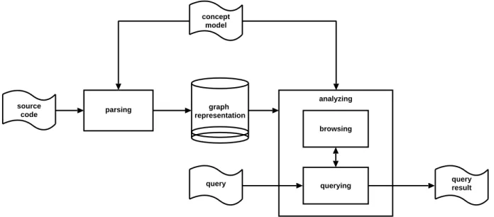
Das Lösungskonzept für diese Forderungen kann durch ein einfaches datenflußartiges Archi- tekturschema dargestellt werden, das gleichzeitig den Rahmen für die Aktivitäten in GUPRO beschreibt. Gesteuert durch ein Konzeptmodell wird die Software durch entsprechende Parser in ein Repository (TGraphen) übersetzt, welches die Basis für die Untersuchungswerkzeuge liefert.
Parsen Quell-
texte
Analysieren
Anfrage
Anfragen Repository
Wartungs- ingenieur
entwickelt
Wartungs-
programmierer Report
Konzept- modell
formuliert
erhält
Browsen
Abbildung 1.1:GUPRO-Architekturschema
IBM - jetzt das wissenschaftliche Zentrum in Heidelberg - und das Institut für Softwaretechnik beschlossen, diesem Ansatz nachzugehen. Aus dem Architekturschema in Abbildung 1.1 konn- ten die folgenden Anforderungen abgeleitet werden:
der Modellierungsansatz sollte so weiterentwickelt werden, daß er sich für den praktischen Einsatz im Programmverstehen eignet,
Die Geschichte vonGUPRO 5 die Erzeugung von Übersetzern von Quelltexten in das Repository sollte möglichst einfach sein,
die Speicherung der abstrakten Syntax im Repository sollte effizient geschehen,
eine für Programmverstehensanwendungen angemessene Anfragesprache sollte entwickelt werden, welche auch noch effizient implementierbar ist,
das Browsing auf Quelltextebene sollte dem Benutzer ermöglicht werden, die Möglichkeiten der Anfrage und des Browsings sollten integriert sein und das Ganze sollte unter einer zeitgemäßen Oberfläche bedienbar sein.
Softwaretechnik-Initiative
Als glücklicher Zufall erwies sich, daß gerade zu dieser Zeit die Inititiative zur Förderung der Software-Technologie in Wirtschaft, Wissenschaft und Technik des Bundesministeriums für Bil- dung, Wissenschaft, Forschung und Technologie (BMBF) aufgelegt wurde. Im Rahmen die- ser Initiative sollten Projekte gefördert werden, die „Methoden und Werkzeuge für die Pflege und Wiederverwendung von Anwendungssystemen“ entwickeln. Um gleichermaßen die wissen- schaftliche Fundierung und Anwendbarkeit der Projektergebnisse zu gewährleisten, sollte ein Projektkonsortium jeweils aus Softwareanwendern, Softwareherstellern und Wissenschaftsein- richtungen bestehen.
Da die Fragen des Programmverstehens überall relevant sind, war es nicht schwer zum IST als Wissenschaftseinrichtung und der IBM als Softwarehersteller einen weiteren Partner aus dem Bereich der Anwendung zu finden: Die Volksfürsorge Unternehmensgruppe, als Geschäftspart- ner der IBM, zeigte Interesse. Es wurde ein gemeinsamer Antrag für das Förderprogramm erstellt und im Herbst 1994 eingereicht.
Das Projekt (und damit auch das hierin zu erstellende Werkzeug) erhielten den NamenGUPRO (Generische Umgebung zum Programmverstehen). Der Antrag zielte darauf ab, sowohl die Be- dürfnisse des Anwenders zu berücksichtigen, als auch forschungsrelevante Fragestellungen zu bearbeiten. Er wurde im Rahmen des Softwaretechnologie-Programms genehmigt und die Ar- beiten anGUPRObegannen im Herbst des Jahres 1995.
Graphentechnologie
DurchGUPROwurde die im IST durchKOGGE teilweise schon vorhandene Technologie durch neue Bausteine ergänzt.
Die Anpaßbarkeit und damit die Flexibilität von GUPRO wird durch die Konzeptmodellierung ermöglicht, die — wie inKOGGE — unter Verwendung einer sehr allgemeinen, visuellen Sche- mabeschreibungssprache (EER), ergänzt durch eine mächtige Sprache zur Formulierung von Kontextbedingungen (GRAL, [Franzke, 1997]) durchgeführt werden kann (vgl. hierzu auch Ka- pitel 3 bzw. [Ebert et al., 1996c]). Im Rahmen vonGUPRO wurde dieser Modellierungsansatz
6 Die Geschichte vonGUPRO noch einmal überarbeitet und in seiner Semantik vollständig formal beschrieben: Durch eine EER/GRAL-Beschreibung ist somit neben der konzeptionellen Modellierung zugleich die Spei- cherstruktur für die verarbeitende Software in Form entsprechender TGraphen festgelegt (vgl.
Kapitel 4 bzw. [Dahm et al., 1998]).
Alle Bausteine vonGUPRO arbeiten aufTGraphen. TGraphensind typisierte, attributierte und angeordnete gerichtete Graphen. Innerhalb des Projekts werden TGraphen als speicherinterne Datenstruktur gehalten. Sie sind in Form des GraLab (vgl. [Dahm/Widmann, 1998] oder eine Kurzfassung des GraLab-Handbuchs in Kapitel 5) als Klassenbibliothek implementiert. Dieses bietet besondere Unterstützung für das Traversieren von Graphen, wie es beim Programmverste- hen besonders häufig benötigt wird.
Anwendungslandschaft
Die Kooperation im Projekt war am Anfang besonders stark. Schließlich galt es, bzgl. der techni- schen Anforderungen miteinander eine gemeinsame Sprache zu finden und die bei den Partnern vorhandenen Vorstellungen und Wünsche miteinander zu vereinbaren.
InGUPROist es möglich, nahezu beliebige Anwendungssichten (sowohl was die Programmier- sprachen betrifft, als auch was die Abstraktionsebene betrifft) zu bearbeiten. Es war der Wunsch der Volksfürsorge, zuerst ein grobkörniges Modell der bei ihr vorhandenen Software (übergrei- fend über alle Programmiersprachen) zu entwickeln. Dieses sollte sowohl der Bestandsanalyse als auch der dann anstehenden Fortentwicklung des Softwarebestandes als Grundlage dienen.
Gemeinsam wurde daraufhin ein solches Modell der gesamten Anwendungslandschaft der Volks- fürsorge (vgl. Kapitel 6 bzw. [Dahm et al., 1995]) entwickelt. Dieses sollte für die gesamte Lauf- zeit des Projekts – als eine Art große Fallstudie – Hauptanwendung für die Modellierung bleiben.
Natürlich wurde das Konzeptmodell im Verlaufe des Projekts mehrfach modifiziert und ergänzt, was jedoch insbesondere durch den gewählten generischen Ansatz problemlos möglich war. Die aktuell verwendete Version des Konzeptmodells ist in Kapitel 7 bzw. in [Kullbach et al., 1998]
gemeinsam mit seiner Anwendung imGUPRO-Prototyp dargestellt.
Am IST wurde gleichzeitig mit einer feinkörnigen Modellierung von C gearbeitet, die auch in ei- nem schemagesteuerten Werkzeug zur konsistenten Veränderung von Quelltexten [Panse, 1998], [Ebert et al., 1998] Verwendung fand. Mit einer Kombination aus GUPRO und dieser Model- lierung beteiligt sich das IST auch am Reverse Engineering Demonstration Project. In diesem internationalen Vergleichsprojekt [WorldPath Information Services, 1998] werden unterschied- liche Ansätze zum Reverse Engineering aus Industrie und Wissenschaft einander gegenüberge- stellt.
Parsing
Um Software gemäß der beschriebenen Anwendungslandschaft repräsentieren zu können, muß- ten zahlreiche Parser geschrieben werden, die so unterschiedliche Dateiinhalte wie Jobkontroll- texte, Datenbankbeschreibungen, COBOL-Programme, CSP-Dateien u.ä. in ein gemeinsames Repository übersetzen.
Die Geschichte vonGUPRO 7 Der Parserbau nahm im gesamten Projekt einen nicht erwarteten Umfang an. Insbesondere die Verarbeitung der COBOL-Dateien bereitete Schwierigkeiten, da im Bestand der Volksfürsorge noch Programme vorhanden waren, deren Sprachversionen längst veraltet und auch nirgendwo beschrieben waren. Die heutigen COBOL-Übersetzer, die die Volksfürsorge einsetzt, können diese Versionen allerdings noch verarbeiten, also mußte der GUPRO-COBOL-Parser dies auch können. Die Kollegen bei der Volksfürsorge waren hier geduldige und kooperative Partner, die in langen Testreihen die Schwachstellen des Parsers herausfanden, so daß zwischenzeitlich ein weitgehend stabiles Werkzeug entstand — und das, obwohl keine schriftlichen Unterlagen über die alten COBOL-Dialekte zu bekommen waren.
Für neuere Sprachen als COBOL wurde in GUPRO ein eigener leistungsfähiger Ansatz ent- wickelt. Die Übersetzung von moderneren Sprachen in TGraphen kann jetzt mit PDL (Par- ser Description Language) geschehen. PDL stellt eine Erweiterung des gängigen Parser- Erzeugungstools yacc/bison um graph-erzeugende Bestandteile dar (vgl. die Einführung zuPDL in Kapitel 8 bzw. [Dahm, 1998]). Die Einheiten des Konzeptmodells können der konkreten Syn- tax der Sprache so zugeordnet werden, daß der größte Teil der TGraph-Erzeugung automatisch geschieht.
Repository
Die interne Repräsentation der zu untersuchenden Softwarestrukturen erfolgt inGUPRO in ei- nem Repository auf der Basis des GraphenlaborsGraLab. Die hierin verwaltetenTGraphenent- halten Referenzen auf die Originalquelltexte. Neben der Beschreibung struktureller Zusammen- hänge der Softwarekomponenten sind hierdurch auch Querverweise in die Quelltexte möglich, die inGUPRO insbesondere das Durchbrowsen der Softwarestrukturen in Quelltextform erlau- ben.
Jeder Übersetzungsprozeß einer Programmeinheit bezieht sich zunächst auf eine einzelne Pro- grammiersprache. Der zugehörige Parser liefert einen Teilgraphen, der in das den gesamten Soft- warebestand repräsentierende Repository integriert werden muß.
Bald entstand die Anforderung, den Gesamtgraphen auch auf Quelltextänderungen hin aktuali- sieren zu können. Also mußte eine Möglichkeit gefunden werden, einmal eingefügte Einheiten aus einem Repository sauber zu entfernen, neu zu übersetzen und wieder adäquat einzufügen. In diesem Zusammenhang wurde ein generelles Konzept entwickelt, mit dessen Hilfe diese Schrit- te so spezifiziert werden, daß sie automatisch durchgeführt werden können. Diese erweiterte Parsing-Strategie ist sicher auch für andere Werkzeuge interessant. Sie wird in Kapitel 9 bzw. in [Kamp, 1998a] dargestellt.
Anfragen und Browsen
Als zentrale Funktionalität von GUPRO können Anfragen an die im Repository vorhandene Software gestellt werden. Durch die Repräsentation der Software alsTGraphenist den Möglich- keiten der Anfrage kaum eine Grenze gesetzt. Gerade den Erreichbarkeitsanfragen innerhalb des vernetzten Repositories kommt eine große Bedeutung zu.
8 Die Geschichte vonGUPRO Orientiert an der im IST bereits vorhandenen SpracheGRAL, die ja die Formulierung von Bedin- gungen an TGraphen unterstützt, wurde eine entsprechende Anfragesprache GReQL(GUPRO Repository Query Language) entwickelt. (Kapitel 10 enthält zur Einführung in diese Anfrage- sprache die GReQL-Sprachbeschreibung aus [Kamp, 1998].) Ein Optimierer ([Polock, 1997]) transformiert die Anfragen, so daß sie in durchaus akteptabler Zeit durch den Auswerter ([Gilles, 1997], [Dahm, 1997]) bearbeitet werden können.
Aufbauend auf der Darstellung der Anfrageergebnisse durch Tabellen, kann zu den Tabellen- Eintragungen das zugehörige Fragment im Quelltext angezeigt werden. Hiervon ausgehend kann dann der Quelltext in mit Hilfe eines Browsers „durchstöbert“ werden.
Oberfläche
Die Oberfläche des GUPRO-Werkzeugs wurde von der IBM in Heidelberg erstellt (vgl. Kapi- tel 11). DaGUPRO gleichzeitig unter OS/2 und unter SUN Solaris lauffähig sein sollte, muß- te dies unter Verwendung einer für beiden Plattformen verfügbaren Software geschehen. Die Schnittstelle zur eigentlichen Applikation wurde zwischen Heidelberg und Koblenz ausgehan- delt.
Die Kollegen bei der IBM schufen eine Oberfläche, die das Eingeben, Ändern und Ausführen vonGReQL-Anfragen unterstützte.
Für die Anwendung in der Praxis warGReQLallerdings zu umständlich (ein Preis für die Univer- salität, die hier zu erreichen versucht wurde). Die Projektpartner der Volksfürsorge wünschten sich eine formularbasierte Eingabeform, die für weniger geübte Anwender einsetzbar ist. Sie sollte mit Hilfe von Auswahllisten erlauben, Anfragen schrittweise zusammenzustellen. Auch diese Oberfläche wurde schließlich von der IBM implementiert.
Die Ergebnisse beider Arten von Anfrageeingaben können einheitlich weiterverarbeitet werden.
DieGUPRO-Oberfläche integriert beide Formen der Anfrage mit dem Browser. Von der tabella- rischen Darstellung der Anfrageergebnisse kann durch einen Maus-Klick in eine Repräsentation durch markierte Textfragmente in den Originalquelltexten umgeschaltet werden. Hiervon ausge- hend kann dann der Text entlang der im Konzeptmodell hinterlegten Querbezüge durchwandert werden.
Ausblick
Insgesamt entstand in Kooperation dreier Projektgruppen ein Werkzeug, das den in 1994 ent- wickelten Wünschen nach unserer Einschätzung voll entspricht. Ein kurzes Handbuch (Kapi- tel 12) liegt auch bereits vor, und der Anwendungspartner Volksfürsorge hatGUPROseit einiger Zeit im Testeinsatz und sieht dessen Verwendung in der Produktion mit Zuversicht entgegen (Kapitel 13).
Überblicksdarstellungen zuGUPROfinden sich in [Ebert et al., 1996a] oder in Kapitel 2 bzw. in [Ebert et al., 1996b]. Einen aktuellen Einblick inGUPROerlaubt auch die WWW-Seite
http://www.uni-koblenz.de/ ist/gupro.html.
Literaturverzeichnis 9 Aus unserer Sicht jedenfalls hat sich das Projekt gelohnt und viele weitere mögliche Fortsetzun- gen bieten sich an, so daß GUPRO als Werkzeug und als konzeptioneller Ansatz sicher noch einige Weiterentwicklungen erfahren wird.
Literaturverzeichnis
[Dahm/Widmann, 1998] P. Dahm, F. Widmann. Das Graphenlabor, Version 4.2. Fachbericht Informatik 11/98, Universität Koblenz-Landau, Institut für Informatik, Koblenz, 1998.
[Dahm et al., 1995] P. Dahm, J. Fricke, R. Gimnich, M. Kamp, H. Stasch, E. Tewes, A. Winter.
Anwendungslandschaft der Volksfürsorge. Projektbericht 5/95, Universität Koblenz-Landau, Institut für Softwaretechnik, Koblenz, 1995.
[Dahm et al., 1998] P. Dahm, J. Ebert, A. Franzke, M. Kamp, A. Winter. TGraphenund EER- Schemata, Formale Grundlagen. Fachbericht Informatik 12/98, Universität Koblenz-Landau, Institut für Informatik, Koblenz, 1998.
[Dahm, 1997] P. Dahm. Architektur desGReQL-Auswerters. Projektbericht 11/97, Universität Koblenz-Landau, Institut für Softwaretechnik, 1997.
[Dahm, 1998] P. Dahm. PDL Reference. Fachbericht Informatik 13/98, Universität Koblenz- Landau, Institut für Informatik, Koblenz, 1998.
[Daute/Horn, 1992] O. Daute, G. Horn. CANAL – Ein Reverse-Engineering-Werkzeug für die Programmiersprache C. Diplomarbeit, Institut für Informatik, Universität Koblenz-Landau, Koblenz, März 1992.
[De Carlini/Linos, 1998] U. De Carlini, P. K. Linos, (eds.). 6th International Workshop on Pro- gram Comprehension. IEEE Computer Society, Washington, June 1998.
[Ebert et al., 1996a] J. Ebert, R. Gimnich, A. Winter. Wartungsunterstützung in heterogenen Sprachumgebungen, Ein Überblick zum Projekt GUPRO. in [Lehner, 1996], S. 263–275.
1996.
[Ebert et al., 1996b] J. Ebert, M. Kamp, A. Winter. Generic Support for Understanding Hete- rogeneous Software. Fachbericht Informatik 3/96, Universität Koblenz-Landau, Fachbereich Informatik, Koblenz, 1996.
[Ebert et al., 1996c] J. Ebert, A. Winter, P. Dahm, A. Franzke, R. Süttenbach. Graph Based Modeling and Implementation withEER/GRAL. in [Thalheim, 1996], pp. 163–178. 1996.
[Ebert et al., 1997] J. Ebert, R. Süttenbach, I. Uhe. Meta-CASE in Practice: a Case forKOGGE. in [Olivé/Pastor, 1997], pp. 203–216. 1997.
[Ebert et al., 1998] J. Ebert, B. Kullbach, A. Panse. The Extract-Transform-Rewrite Cycle - A Step towards MetaCARE. in [Nesi/Lehner, 1998], pp. 165–170. 1998.
[Franzke, 1997] A. Franzke. GRAL: A Reference Manual. Fachbericht Informatik 3/97, Univer- sität Koblenz-Landau, Fachbereich Informatik, Koblenz, 1997.
10 Die Geschichte vonGUPRO [Gilles, 1997] C. Gilles. Beschreibung des Kernauswerters. Projektbericht 14/97, Universität
Koblenz-Landau, Institut für Softwaretechnik, Koblenz, 1997.
[Kamp, 1998] M. Kamp. GReQL, Eine Anfragesprache für dasGUPRO-Repository, Sprachbe- schreibung (Version 1.2)). Fachbericht Informatik 14/98, Universität Koblenz-Landau, Institut für Informatik, Koblenz, 1998.
[Kamp, 1998a] M. Kamp. Managing a Multi-File, Multi-Language Software Repository for Program Comprehension Tools – A Generic Approach. in [De Carlini/Linos, 1998], pp. 64–
71. 1998.
[Kullbach et al., 1998] B. Kullbach, A. Winter, P. Dahm, J. Ebert. Program Comprehension in Multi-Language Systems. in Proceedings of 5th IEEE Working Conference on Reverse Engineering, October 12th - October 14th, 1998 Honolulu, Hawaii (to appear). 1998.
[Lehner, 1996] F. Lehner, (Hrsg.). Softwarewartung und Reengineering, Erfahrungen und Ent- wicklungen. Gabler, Wiesbaden, 1996.
[Nesi/Lehner, 1998] P. Nesi, F. Lehner, (eds.). Proceedings of the 2nd Euromicro Conference on Software Maintenance & Reengineering. IEEE Computer Society, Los Alamitos, 1998.
[Olivé/Pastor, 1997] A. Olivé, J. A. Pastor, (eds.). Advanced Information Systems Engineering, 9th international Conference, CAiSE’97, in: LNCS 1250. Springer, Berlin, 1997.
[Panse, 1998] A. Panse. Konzeption und Realisierung eines Reengineering-Werkzeugs. Eine Fallstudie desETR-Zyklus. Diplomarbeit D 432, Universität Koblenz-Landau, Fachbereich Informatik, Koblenz, Januar 1998.
[Polock, 1997] D. Polock. Ein statischer Optimierer für GRAL- undGReQL-Ausdrücke. Di- plomarbeit D-414, Universität Koblenz-Landau, Fachbereich Informatik, Koblenz, September 1997.
[Thalheim, 1996] B. Thalheim, (ed.). Conceptual Modeling — ER’96, in: LNCS 1157. Sprin- ger, Berlin, 1996.
[WorldPath Information Services, 1998] WorldPath Information Services. Reverse Engineering Demonstration Project. http://www.worldpath.com/reproject/, 1998.
2 GUPRO : A Generic System to
Support Multi-Level Understanding of Heterogeneous Software
Jürgen Ebert, Manfred Kamp, Andreas Winter
Abstract
This paper presents the ideas and the implementation ofGUPRO, a generic support system for understanding heterogeneous software. GUPRO provides a seamless approach for modeling, representing and analyzing software.
The focus ofGUPROis its adaptability to (almost) arbitrary kinds of source text. Software of dif- ferent programming and description languages can be represented uniformly by a homogeneous internal representation at any level of granularity. The relevant concepts of the software are described by the maintenance engineer with regard to his or her current program understanding task in a conceptual model using EER–like graphical language.
Then parsers are generated to transform source code into a TGraph representation which is an instance of the model. A parser description language has been developed which supports graph creation according to a conceptual model. A source language independent query language allows the computation of arbitrary reports on the software graphs. The properties of graphs can be used for easily querying even complex structural relationships between instances of the modeled software concepts.
The components of the system are integrated in a framework architecture under a common graph- ical user interface.
Keywords: graph based modeling, program database, program understanding, reengineering, software maintenance, source code independent query language,EER/GRAL.
2.1 Introduction
Software maintenance is the most difficult and certainly the most expensive task of the software lifecycle. Often the source code is the only reliable (and sometimes even the only existing) source for retrieving information about a legacy system. Therefore, program understanding is
published as Fachbericht Informatik 6/97, Universität Koblenz-Landau, Fachbereich Informatik, 1996.
11
12 A Generic System to Support Multi-Level Understanding one of the key tasks in the software maintenance process [Corbi, 1989]. Due to the enormous size and complexity of industrial scale software systems, tools have to be developed to support it.
Program understanding is a basic necessity for a wide range of goals as reported in many pub- lications. These goals vary from recognizing the overall architecture (e. g. [Wong et al., 1995], [Harris et al., 1995]) over assigning parts of the software to aspects of the application domain (e. g. [Boldyreff et al., 1996]) to detecting defects or violations of coding standards in single statements of single source files (e. g. [Wells et al., 1995]). In most cases the level of granular- ity required will vary during a program understanding process. Thus, program understanding in general has to provide multi-level support.
Furthermore, an understanding tool must provide facilities to cross the boundaries of source files of different kinds because in most real world environments a maintenance engineer has to deal with heterogeneous software.
In most cases the software maintenance process (including program understanding) is a goal directed activity addressing a special task [Wong, 1996]. Due to this program understanding support should enable the maintenance engineer to focus on the relevant concepts of the software under examination, e. g. call relationships, global variables etc. To achieve this, one needs either a large number of tools addressing special maintenance issues or tools that are adaptable.
Another important requirement on tools supporting program understanding is that they pro- vide engineers with high assurance of what the tool’s results mean, i.e. he or she has to know which information is and which is not gathered from the source code and how this is done [Sullivan, 1996]. In [Murphy et al., 1996] this requirement is witnessed by an empirical study on the different results computed by parser–based call graph extractors.
A real world example for a reengineering scenario leading to all of these goals is the introduction of a single European currency [European Union, 1995]. This requries changing all software working with a national currency to deal with the ’Euro’.
In searching for program units that might be affected a maintenance engineer may start by look- ing at the database fields defined for storing amounts of money. Then he or she has to find out which programs read or write these data and perhaps call other programs with the use of param- eters. This can be done using a very coarse-grained model of the software system. Detected programs have then to be examined on the level of single statements to find out the necessary changes. A multi-level support is needed. A lot of applications in financial business have grown over decades. Different programming languages, database systems and operating systems are used. The engineers have to cope with heterogeneous software.
At the mentioned coarse-grained level of examination there are only few relevant concepts of the source code that are of interest, i.e. database accesses and program calls. Other concepts will be required for other maintenance task, e. g. for the ’year 2000’–problem where database and record definitions would be of special interest.
When large software systems are under maintenance the decision whether a special subsystem has to be examined by a programmer or not may depend on the results provided by a program understanding tool. As this decision might be quiet expensive, high assurance with respect to the interpretation of the results is required.
2.1 Introduction 13 The GUPRO (Generic Understanding of PROgrams) [Ebert et al., 1996a] approach addresses the goals mentioned. The maintenance engineer is enabled to employ his or her own view of the source code under examination with respect to
the level of granularity needed, the languages involved, and the relevant concepts
in an unambiguous manner. This results in a conceptual model of the software.
The conceptual model is represented by a concept diagram which is described in terms of ex- tended entity–relationship (EER) diagrams as a formal modeling method.
Parsers are generated that transform source code into instances of the given conceptual model which yields a language independent graph representation of the source code.
TheGUPROtoolset consists of three major parts
a parser generator to generate parsers which transform source code into graphs according to the conceptual models
a repository to store the conceptual models and the graph representation and the source code
an analyzing facilities to retrieve the stored information by querying and browsing
These components are integrated in a framework architecture under a common graphical user interface.
parsing source
code
analyzing
query result
query querying
graph representation
concept model
browsing
Figure 2.1: Architecture of a customizedGUPROsystem
TheGUPROapproach is generic in the sense that parsers are generated to perform source–code–
to–graph transformations according to the user–defined conceptual model. So the system can be customized to support arbitrary program understanding tasks.
Figure 2.1 sketches the architecture of a customizedGUPRO system consisting of parsing and analyzing components, connected by graph representations and guided by conceptual models.
14 A Generic System to Support Multi-Level Understanding This paper surveys the methods and tools developed and planned in the GUPRO project to support program understanding. Section 2.2 gives an introduction to modeling software using TGraphsand the outlines the way source code is transformed into a graph representation. Section 2.3 provides a brief description of the language designed to query the program database. Then, in section 2.4 the overall architecture of theGUPRO toolset and the current implementation is outlined. Section 2.4.3 describes the real world environmentGUPROhas to cope with. Related work is cited in each of the sections.
2.2 Representing Software
In this section the graph modeling ideas underlying GUPRO are discussed. The realization of GUPROfollows theEER/GRALgraph modeling approach. A broader discussion ofEER/GRAL, its implementation and its applications is given in chapter 3 resp. in [Ebert et al., 1996b].
2.2.1 TGraphs
To provide a reliable foundation for tool building a formal basis is needed for constructing con- ceptual models of software, for transforming the source code into an appropriate abstract repre- sentation and for retrieving information from this representation.
Objects (like software modules or single statements) and their relationships (like inclusion or calls) are represented as vertices and arcs ofTGraphsin theGUPROrepository.
TGraphs are typed, attributed, ordered, directed Graphs [Ebert/Franzke, 1995]. The sets of vertices and edges in these graphs are each partitioned into subsets representing different types.
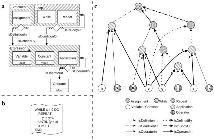
These types are organized into an inheritance hierarchy. Each edge or vertex can be annotated by additional attributes depending on its type. In order to allow modeling of sequences and to make graph traversals deterministic the edges incident to a vertex have a fixed order. Figure 2.2 c shows a little example graph representing the source code of figure 2.2 b. Edges are numbered with respect to their order where necessary.
Graphs of the same kind form graph classes that are defined declaratively by concept diagrams.
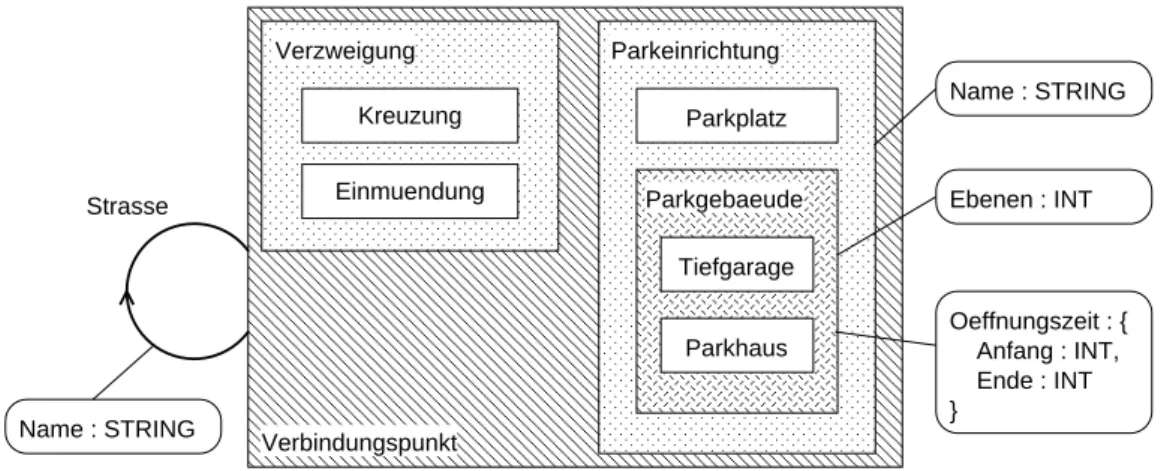
Figure 2.2 a depicts the concepts of regular control structures of an example programming lan- guage. The entity rectangles correspond to vertex types, the arrows represent edges types. Ac- cordingly, the concepts of the programming languages are modeled by vertex types, and relation- ships between these concepts are modeled by edge types. Thus, the reengineer chooses a graph class according to his or her view on the maintenance problem.
The graphical language for describing graph classes is defined in [Carstensen et al., 1995]. A TGraphsemantics is given to concept diagrams, i.e. concrete graphs are instances of a conceptual model. The language permits conceptual modeling by using generalization1and aggregation of concepts and (directed) relationships.
For describing generalization a Venn–notation is used, i.e. including boxes symbolize generalizations of the types represented by the included boxes. If a box is filled with a line pattern the generalization is total.
2.2 Representing Software 15
WHILE x > 0 DO REPEAT y := y+1 UNTIL (y = x) x := x-1 END
0 > = x y + 1 -
While
Assignment Repeat
Application Variable, Constant
Operator isDefinitionIn
isConditionOf isOperatorIn
isDefinedBy isInBodyOf isOperandIn
Assignment While Repeat
Loop
Application Variable
ident
Constant value
Operator ident Statement
Expression
isInBodyOf isConditionOf
isDefinedBy isDefinitionIn
isOperatorIn isOperandIn
a
b
c
1
1 2
2
2
2 1 2
1 1
Figure 2.2: A concept diagram for a simple programming language (a), a source text (b) and the corresponding graph according to the conceptual model (c)
Related Work. TGraphs are not the only possibility to represent software in a re- pository. Other representations as e. g. relational databases [Chen et al., 1990], Prolog databases [Jarzabek/Keam, 1995], abstract syntax trees [Wells et al., 1995], LISP images [Newcomb, 1995] and hybrid knowledge bases [Jarzabek, 1995] have been proposed.
Obviously there is not the one and only solution to cope with all the problems arising in the field of program understanding. But we see significant benefits in the use ofTGraphs.
Graphs in general are a well–understood formalism that comes along with well known and efficient algorithms.
The TGraph concept provides a formal foundation (given in a specification [Spivey, 1992]). This is absolutely necessary to achieve a consistent design, specification and im- plementation of tools working upon the repository and to integrate partial submodels.
Graph classes (which correspond to conceptual models) can be described in terms of the widely known EER model. Communication between people about concepts is also sup- ported.
TheEER/GRALapproach supports a seamless transition from specification of the formal- ism via describing conceptual models down to the efficient implementation as graph data structures.
16 A Generic System to Support Multi-Level Understanding The computation of closures of relationships is possible in an efficient manner. This feature is often required in program understanding tasks e. g. to compute direct and indirect calls when only direct calls are known.
This is advantageous especially in comparison to relational databases where computing long join chains results in poor performance [Linton, 1984].
The use of directed relationships avoids storing two relationships instead of one when a dis- tinction of the direction is required, cf. e. g. the frequently needed ’include’–relationship.
2.2.2 Modeling
As stated in the introductionGUPROallows the user to model the relevant parts of software at an arbitrary level of granularity by choosing more or less abstract concepts. Which objects are to be included into the model and which are unnecessary depends on the information the engineer wants to retrieve from the source code.
Deciding what to include and what to ignore is an art [Wong et al., 1995] and therefore it depends on the experiences and abilities of the modeler. But some rules can be recommended to achieve good conceptual models. They form a very general ’modeling philosophy’:
Each relevant object should be represented by exactly one vertex.
Each use of an object by another object should be represented by an arc. E. g. a variable is represented by exactly one vertex. Its declaration in a procedure header, its occurrence in assignments and its usages in expressions are represented by typed arcs connecting the variable object to the objects representing the mentioned concepts.
Object and relationship types modeling similar information are subsumed into a common vertex resp. edge type using generalization. E. g. statements of different kinds (assign- ments, procedure calls and so on) can be generalized to a supertype called statement.
Further informations about objects or relationships (e. g. the position in the corresponding source code) are stored in attributes according to the vertex resp. edge type.
Thus, adaptingGUPRO to a given maintenance problem starts with identifying the objects and relationships of interest and with developing a model for graphs representing them. This is done by designing a concept diagram following theEER/GRALapproach. Thereby, the class of TGraphrepresenting concrete software is defined. The following two examples should demon- strate the wide range of possibilities to model software:
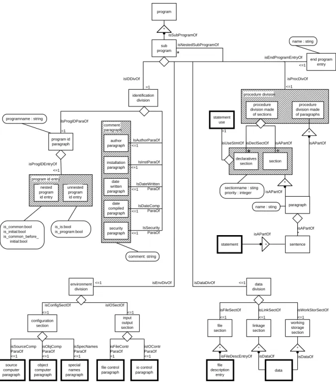
Example 1. Figure 2.3 shows an extract of a fine-grained model of single COBOL programs2. Due to the size of COBOL [Schuelein, 1992] only an extract can be presented3.
Thick framed boxes in this figure are refined in other diagrams.
The complete model consists of about 400 concepts with about 250 relationship types subsumed in 85 diagrams [Hümmerich, 1995].
2.2 Representing Software 17
IsDateComp ParaOf IsDateWritten ParaOf
IsSecurity ParaOf isIDDivOf
isEnvDivOf isDataDivOf
isEndProgramEntryOf
isProcDivOf isSubProgramOf
isNestedSubProgramOf
<=1 not_rigid end program
entry name : sting
is_common:bool is_initial:bool is_common_before_
initial:bool
is_is:bool is_program:bool
IsProgIDParaOf
<=1 identification
division
<=1
<=1
<=1
<=1
=1
<=1 isProgIDEntryOf
=1
programname : string
program id entry nested program id entry
not_rigidunnested program
id entry program id paragraph
comment: string
<=1
+ isAPartOf isAPartOf
+
isAPartOf
isAPartOf
isAPartOf paragraph
* procedure division made of paragraphs procedure division
procedure division made
of sections
section isUseStmtOf
=1
isDeclSectOf
* +
declaratives section
sectionname : sting priority : integer
name : sting +
<=1
input output section environment
division
configuration section
<=1 =1
<=1 <=1 <=1
<=1 <=1
isConfigSectOf isIOSectOf
isSourceComp ParaOf
isObjComp ParaOf
isSpecNames ParaOf
isFileContr ParaOf
isIOContr ParaOf
<=1
working storage section file
section
data division
linkage section
*
* *
isFileSectOf isLinkSectOf isWorkStorSectOf
isFileDescEntryOf isDataOf isDataOf
<=1 <=1 <=1
program
+
sub program
*
author paragraph
installation paragraph
date written paragraph
date compiled paragraph
security paragraph comment paragraph
IsAuthorParaOf
IsInstParaOf
statement sentence
statement use
source computer paragraph
object computer paragraph
special names paragraph
file control paragraph
io control paragraph
file description
entry
data
Figure 2.3: Concept diagram modeling COBOL fine-grained (extract)
Obviously, the level of abstraction of this model comes close to abstract syntax trees. But fol- lowing the above mentioned modeling rules the instance graphs of the schema are not trees but general graphs. This leads to a more compact and easy–to–analyze representation of the abstract syntax.
Since every instance of the COBOL graph class represents exactly one single COBOL program a parser has to be built which translates COBOL programs to graphs.
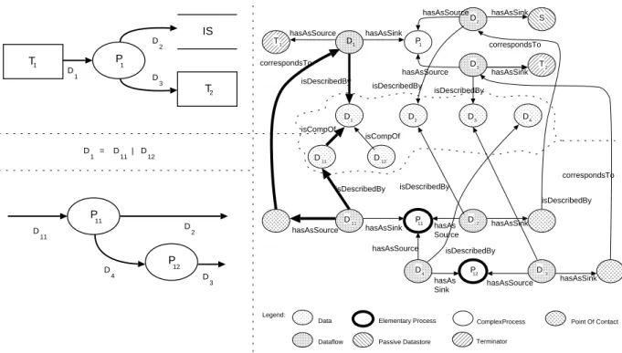
18 A Generic System to Support Multi-Level Understanding Example 2. Another conceptual model was developed together with the project partners (cf.
chapter 6 resp. [Dahm et al., 1995]). Here, the aim was to design a model that provides high–
level information about the relationships among programs and between programs and data used at the Volksfürsorge insurance company. In contrast to the COBOL graph class this requires a coarse-grained model that on one hand hides unnecessary details and on the other hand keeps the graph in a manageable size.
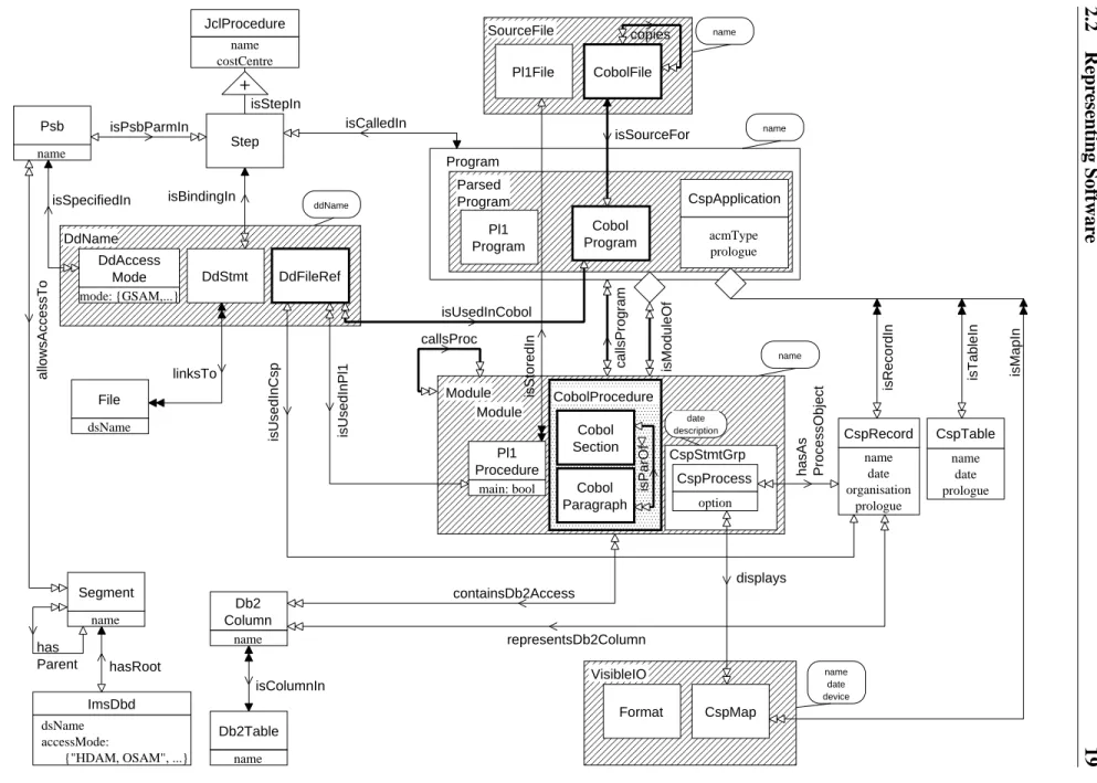
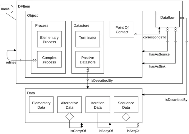
The software landscape of Volksfürsorge consists of COBOL, PL/I (both with embedded SQL) and CSP (a 4GL COBOL generator with its own SQL dialect). The data are stored in files, hierarchical IMS databases and a relational DB2 database. JCL (job control language) proce- dures activate the programs and determine which data is processed by the programs. All these components are represented by one conceptual model called the ’application landscape’ (figure 2.4).
The whole software configuration is represented by one single graph corresponding to the con- cept diagram. Parsers have been written for each of the languages occurring in the model. They incrementally build up the graph.
Analysing an instance of that model might result in detecting a COBOL program of interest e. g.
because of its relationship to a special file. If further examination of the program is required an instance of the finer-grained model can be created.
Related Work. Many kinds of ER or EER models are used to represent concepts of software in the field of program understanding. Graphical [Jarzabek, 1995], [Canfora et al., 1996] and textual languages [Wells et al., 1995]) are used which sometimes lack formal semantics.
As GUPRO allows multi–level modeling the graphical modeling language of EER/GRAL was chosen to represent the conceptual models. This approach avails graphical object–oriented mod- eling (known by many users, use of inheritance, use of cardinality constraints etc.) while provid- ing a well defined semantics.
2.2.3 Transforming Source Code into Graphs
Source code is transformed into a graph representation by parsers. These are in most cases generated from descriptions written in PDL (Parser Description Language [Dahm, 1995]; cf.
chapter 8). PDL is an extension to the widely used parser/scanner generators lex and yacc [Brown et al., 1992]. It is especially tailored to the description of parsers which generate graphs according to a conceptual model.
APDLdescription contains
a textual EER specification of a conceptual model
the grammar of the language to be parsed in EBNF notation
statements for creating graph elements corresponding to the given conceptual model as semantic actions and for the use of a build in block oriented symbol table
If the parser adds elements to a single graph which has to be built incrementally by several parsers (see example 2) there is an additional graph manipulation phase that integrates the created subgraph into the existing graph.
2.2RepresentingSoftware19
Module
isParOf
CobolProcedure Cobol Section
Cobol Paragraph
callsProgram
callsProc
isModuleOf
has Parent
Segment name
File dsName
isColumnIn
Db2Table name Db2 Column
name linksTo
hasRoot Psb
name
Format
displays
name date device
Cobol Program
CspStmtGrp name
date prologue CspTable name
date organisation
prologue CspRecord CspApplication
acmType prologue
Module
CspMap VisibleIO
hasAs ProcessObject isTableIn
isRecordIn isMapIn
Program
ImsDbd dsName accessMode:
{"HDAM, OSAM", ...}
JclProcedure name costCentre
representsDb2Column
CspProcess option
isUsedInCsp
Parsed Program
name
Pl1File CobolFile
SourceFile name
isSourceFor
isStoredIn
isPsbParmIn isCalledIn
isStepIn Step
isUsedInPl1
DdAccess Mode mode: {GSAM,...}
DdName
DdFileRef isBindingIn
isSpecifiedIn
Pl1 Program
allowsAccessTo
ddName
Pl1 Procedure
main: bool
containsDb2Access DdStmt
isUsedInCobol
+
copies
name
date description
Figure2.4:Theapplicationlandscape
20 A Generic System to Support Multi-Level Understanding As an example the thick lines in figure 2.4 mark the concepts whose instances are created by the incremental COBOL parser.
Related Work. Other parser generator tools have been examined during the project. Cocktail [Grosch/Emmelmann, 1990] has been used for generating one of the incremental parsers. Like PDL it allows to describe the grammar in EBNF. PRECC [Breuer/Bowen, 1993] generates re- cursive descend parsers. Problems occurred in the control of backtracking in connection with graph manipulating actions. These tools do not offer special support for graph manipulation in their language, of course.
PDLprovides special language concepts for this purpose and seamlessly fits to the EER/GRAL approach.
2.3 Querying the Repository
This section describes how the TGraph representation of software can be used for analysis.
GUPRO contains an analysis component which is independent of the programming language and the level of granularity chosen.
For retrieving information from graphs in the repository a query language called GReQL (GUPRO Repository Query Language) has been developed [Kamp, 1996] (cf. chapter 10) which seamlessly suits to theEER/GRALapproach. TheGReQLsemantics is operationally defined by giving a translation of aGReQLinput into expressions which is based upon the specification ofTGraphs.
GReQLincludes a function and relation library providing many graph–related computations (e. g.
’neighbours’ which yields a list of the neighbours of a given vertex or ’isLoop’ which tests whether a given edge is a loop). This library is based on GRAL [Franzke, 1997] a language designed to express predicates forTGraphs.
AGReQLquery always addresses a single graph in the repository. In order to write meaningful queries the corresponding conceptual model has to be known by the user.
The general form of a simpleGReQLquery (called a FWR–expression) is as follows:
FROM
WITH REPORT
END
In the FROM part variables are declared via types and classes of the concept diagram, where a class comprises a type and all its subtypes. The (optional) WITH part contains a predicate using the declared variables in terms of first order logic. The expression list of theREPORTpart describes the query’s results. These are collected in a bag.
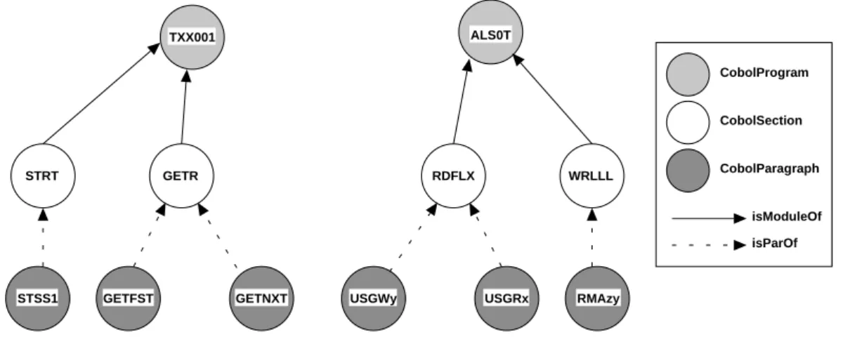
The following query addresses a graph according to the application landscape (figure 2.4). It provides the names of all sections and their paragraphs of the COBOL program ’TXX001’. The result consists of pairs of a section name and paragraph name where the paragraph is part of the section.
2.3 Querying the Repository 21 FROM prog: V{CobolProgram},
sec: V{CobolSection}, para: V{CobolParagraph}
WITH prog.name = ’TXX001’ AND sec -->{isModuleOf} prog AND sec <--{isParOf} para REPORT sec.name, para.name END
Assuming the graph to be the one shown in figure 2.5 this leads to the result:
(’STRT’, ’STSS1’), (’GETR’, ’GETFST’), (’GETR’, ’GETNXT’)
TXX001
GETR STRT
GETFST STSS1
CobolProgram
CobolSection
CobolParagraph
isModuleOf isParOf
RDFLX WRLLL
USGRx
USGWy RMAzy
GETNXT
ALS0T
Figure 2.5: Instance of the application landscape
The evaluation of a query can be considered as an iteration including two steps. For all possible assignments to the declared variables
1. the predicate is tested and
2. if the predicate is fulfilled, the expression list is computed and the resulting tuple is added to the result bag.
Since an FWR–expression is an expression it can be used wherever expressions are allowed (e. g. it can be combined with aggregation functions to compute numeric information or it can be nested in a result expression list of another FWR–expression to get structured results).
The main feature of GReQL(and GRAL) are path descriptions like sec -->{isModuleOf}
prog. They allow to describe regular structured relationships, i. e. sequences, alternatives and iterations of paths. This includes the computation of transitive and reflexive closures.
The following situation, reported as a common problem in maintaining heterogeneous software, leads to a more complex query: As there occurred too many deadlocks with respect to a special DB2 table (named ’PRINFO’) the maintenance engineer wants to know which JCL procedures should not be run in parallel to avoid this.
So one has to ask for every JCL procedure that calls a program which accesses this DB2 table or which directly or indirectly calls a program accessing it. This is expressed by the following query again according to the application landscape of figure 2.4.
22 A Generic System to Support Multi-Level Understanding
\*1*\ distinct(
\*2*\ FROM jcl: V{JclProcedure}, tab: V{Db2Table}
\*3*\ WITH tab.name = ’PRINFO’ AND
\*4*\ tab <--{isColumnIn}
\*5*\ (<--{containsDb2Access}-->{isModuleOf}
\*6*\ | <--{representsDb2Column}-->{isRecordIn})
\*7*\ (<--{callsProgram}-->{isModuleOf})*
\*8*\ -->{isCalledIn} jcl
\*9*\ REPORT jcl.name END )
The first three lines of the path description (4–6) lead to objects of type which access the database table. Two paths (via or ) are possible for this. Then, line 7 points to all programs that call these objects directly or indirectly. The last part of the path (8) finally leads to the calling JCL procedures. The ’distinct’ function removes all duplicates from the resulting bag.
Please note that it is necessary to compute the transitive closure for the path
<-{callsProgram}->{isModuleOf}in line 7 to answer this query. Due to the graph–based model and its implementation, the query evaluation can be done efficiently.
Related Work. There are many approaches reported for retrieving information about pro- grams. In [Jarzabek, 1995] PQL is introduced. This language looks similar toGReQLbut does not offer the possibility to query complex structural relationships or to compute closures (as path descriptions do). As there is no specific database calculus underlying PQL, managing the complexity and efficiency of query evaluation seems to be very difficult.
A well defined query algebra is proposed in [Paul/Prakash, 1996]. The EER model used differs from the modeling approach used in GUPRO since relations are modeled by attributes. These are usable in only a single direction e. g. if a ’calls’–relationship is stored in the database the ’is- called-by’–relationship has to be computed before it can be used. Furthermore, our experiences during the developmentGReQLsuggest that it would be very difficult to convince practitioners to use a query algebra instead of a language with a more common syntax and semantics.
Other approaches use pattern–based query languages for program databases [Paul/Prakash, 1994]
[Wells et al., 1995]. These always require a representation at the granularity level of syntax trees which is not the case in theGUPROapproach.
SQL/EER [Hohenstein/Engels, 1992] [Andries/Engels, 1994] is a query language addressing an object–oriented data model. Although the underlying modeling approach differs from GUPRO in some important details, syntax and semantics ofGReQLare influenced by it.
2.4 Building the Tool
This section sketches the overall architecture of theGUPROsystem. It describes the components of the system and reports about the current implementation and its employment.
2.4 Building the Tool 23
2.4.1 The Overall Architecture
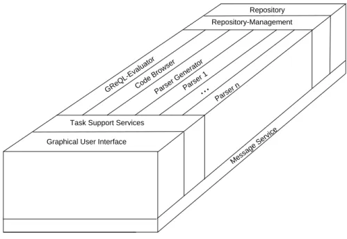
The GUPRO toolset contains several interacting components. Its architecture can be de- scribed along with the ECMA model for computer assisted software engineering frameworks [Earl, 1991], i.e. it consists of a repository backend, a user frontend, several tools in between and some service units to support users and to manage the inter-tool communication (see figure 2.6).
Message Service GReQL-Evaluator Parser 1
Parser n
...
Task Support Services Graphical User Interface
Repository Repository-Management
Code Browser Parser Generator
Figure 2.6: TheGUPROarchitecture
The repository contains the data described in the previous sections, i.e. graphs, conceptual mod- els and the source code.
Parsers are added by the parser generator. The repository is filled by the parsers. Information is retrieved by theGReQLevaluator. Currently a prototype of a graph–based code browser is under development which navigates on a GUPROgraph while displaying the code represented by the current vertex. Due to the open design of the architecture other tools like a concept diagram editor can (and should) be integrated in future.
The frontend which is currently under construction at the IBM Scientific Center Heidelberg pro- vides a graphical user interface for parsing source code, writing and evaluatingGReQLqueries and displaying the result.
2.4.2 Technical Aspects
TheGUPROsystem is implemented using C++with RogueWave Tools.h [RogueWave, 1996] as a basic library while the StarView class library [StarDivision, 1995] is used to build the GUI.
GUPROis simultaneously implemented for the OS/2 and the SUN Solaris operating system.
TGraphs are implemented using the C++ class library GraLab (Graph Laboratory, cf. chap- ter 5) that provides classes and methods for the construction, manipulation and traversal of graphs [Dahm et al., 1994]. It uses a data structure optimized to the needs of efficient traver-
24 A Generic System to Support Multi-Level Understanding sal [Ebert, 1987]. Graphs are kept in core memory for building and querying while being stored persistently as (readable) ASCII files.
Parsers exist for the COBOL, the CSP, the JCL and (as a prototype) the PL/I parts of the ap- plication landscape (figure 2.4). The JCL parser and parts of the COBOL parser have been generated using PDL. The CSP parser has been built using the ’Cocktail’ parser generator [Grosch/Emmelmann, 1990]. Since common parser generators are not able to deal with the special properties of column-oriented languages like COBOL and MVS-JCL special lexical an- alyzers had to be implemented by hand.
A prototype of theGReQLevaluator is operable now. Queries are transformed into the equiva- lent expressions (internally represented as graphs) for evaluation. An extensive function and relation library is provided.
The GUI is under implementation at the IBM Scientific Center Heidelberg. It allows writing, editing and evaluatingGReQLqueries as well as storing them for reuse. Results of queries are displayed as tables. Parsing can also be started and supervised using the GUI.
Message passing to the GUI is done by all components (except of the parsers which are stand- alone executables) using theC++exception handling mechanism.
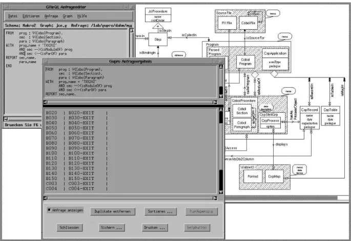
Figure 2.7 shows a screenshot of the current GUPRO system, a query–window and a result–
window. The diagram in the background is displayed by a postscript viewer. Currently the GUI is implemented using german menus and labels.
Figure 2.7: A screenshot of theGUPROsystem