Model 2100 6 1/2-Digit Resolution Digital Multimeter User’s Manual
2100-900-01 Rev. B / July 2007
A G R E A T E R M E A S U R E O F C O N F I D E N C E
Keithley Instruments, Inc.
Corporate Headquarters • 28775 Aurora Road • Cleveland, Ohio 44139 440-248-0400 • Fax: 440-248-6168 • 1-888-KEITHLEY (1-888-534-8453) • www.keithley.com
Keithley Instruments, Inc. warrants this product to be free from defects in material and workmanship for a period of one (1) year from date of shipment.
Keithley Instruments, Inc. warrants the following items for 90 days from the date of shipment: probes, cables, software, rechargeable batteries, diskettes, and documentation.
During the warranty period, Keithley Instruments will, at its option, either repair or replace any product that proves to be defective.
To exercise this warranty, write or call your local Keithley Instruments representative, or contact
Keithley Instruments headquarters in Cleveland, Ohio. You will be given prompt assistance and return instructions.
Send the product, transportation prepaid, to the indicated service facility. Repairs will be made and the product returned, transportation prepaid. Repaired or replaced products are warranted for the balance of the original warranty period, or at least 90 days.
LIMITATION OF WARRANTY
This warranty does not apply to defects resulting from product modification without Keithley Instruments’ express written consent, or misuse of any product or part. This warranty also does not apply to fuses, software,
non-rechargeable batteries, damage from battery leakage, or problems arising from normal wear or failure to follow instructions.
THIS WARRANTY IS IN LIEU OF ALL OTHER WARRANTIES, EXPRESSED OR IMPLIED, INCLUDING ANY IMPLIED WARRANTY OF MERCHANTABILITY OR FITNESS FOR A PARTICULAR USE. THE REMEDIES PROVIDED HEREIN ARE BUYER’S SOLE AND EXCLUSIVE REMEDIES.
NEITHER KEITHLEY INSTRUMENTS, INC. NOR ANY OF ITS EMPLOYEES SHALL BE LIABLE FOR ANY DIRECT, INDIRECT, SPECIAL, INCIDENTAL, OR CONSEQUENTIAL DAMAGES ARISING OUT OF THE USE OF ITS INSTRUMENTS AND SOFTWARE, EVEN IF KEITHLEY INSTRUMENTS, INC. HAS BEEN ADVISED IN ADVANCE OF THE POSSIBILITY OF SUCH DAMAGES. SUCH EXCLUDED DAMAGES SHALL INCLUDE, BUT ARE NOT LIMITED TO: COST OF REMOVAL AND INSTALLATION, LOSSES SUSTAINED AS THE RESULT OF INJURY TO ANY PERSON, OR DAMAGE TO PROPERTY.
6 1/2-Digit Resolution Digital Multimeter User’s Manual
©2007, Keithley Instruments, Inc.
All rights reserved.
Cleveland, Ohio, U.S.A.
2100-900-01 Rev. B / July 2007 Document Number:
All Keithley Instruments product names are trademarks or registered trademarks of Keithley Instruments, Inc.
Other brand names are trademarks or registered trademarks of their respective holders.
Manual Print History
The print history shown below lists the printing dates of all Revisions and Addenda created for this manual. The Revision Level letter increases alphabetically as the manual undergoes subsequent updates. Addenda, which are released between Revisions, contain important change information that the user should incorporate immediately into the manual. Addenda are numbered sequentially. When a new Revision is created, all Addenda associated with the previous Revision of the manual are
incorporated into the new Revision of the manual. Each new Revision includes a revised copy of this print history page.
Revision A (Document Number 2100-900-01) ...June 2007 Revision B (Document Number 2100-900-01) ... July 2007
06/07 The following safety precautions should be observed before using this product and any associated instrumentation. Although some instruments and accessories would normally be used with non-hazardous voltages, there are situations where hazardous conditions may be present.
This product is intended for use by qualified personnel who recognize shock hazards and are familiar with the safety precautions required to avoid possible injury. Read and follow all installation, operation, and maintenance information carefully before using the product. Refer to the user documentation for complete product specifications.
If the product is used in a manner not specified, the protection provided by the product warranty may be impaired.
The types of product users are:
Responsible body is the individual or group responsible for the use and maintenance of equipment, for ensuring that the equipment is operated within its specifications and operating limits, and for ensuring that operators are adequately trained.
Operators use the product for its intended function. They must be trained in electrical safety procedures and proper use of the instrument.
They must be protected from electric shock and contact with hazardous live circuits.
Maintenance personnel perform routine procedures on the product to keep it operating properly, for example, setting the line voltage or replacing consumable materials. Maintenance procedures are described in the user documentation. The procedures explicitly state if the operator may perform them. Otherwise, they should be performed only by service personnel.
Service personnel are trained to work on live circuits, perform safe installations, and repair products. Only properly trained service personnel may perform installation and service procedures.
Keithley Instruments products are designed for use with electrical signals that are rated Measurement Category I and Measurement Category II, as described in the International Electrotechnical Commission (IEC) Standard IEC 60664. Most measurement, control, and data I/O signals are Measurement Category I and must not be directly connected to mains voltage or to voltage sources with high transient over-voltages. Measurement Category II connections require protection for high transient over-voltages often associated with local AC mains connections. Assume all measurement, control, and data I/O connections are for connection to Category I sources unless otherwise marked or described in the user documentation.
Exercise extreme caution when a shock hazard is present. Lethal voltage may be present on cable connector jacks or test fixtures. The American National Standards Institute (ANSI) states that a shock hazard exists when voltage levels greater than 30V RMS, 42.4V peak, or 60VDC are present. A good safety practice is to expect that hazardous voltage is present in any unknown circuit before measuring.
Operators of this product must be protected from electric shock at all times. The responsible body must ensure that operators are prevented access and/or insulated from every connection point. In some cases, connections must be exposed to potential human contact.
Product operators in these circumstances must be trained to protect themselves from the risk of electric shock. If the circuit is capable of operating at or above 1000V, no conductive part of the circuit may be exposed.
Do not connect switching cards directly to unlimited power circuits. They are intended to be used with impedance-limited sources. NEVER connect switching cards directly to AC mains. When connecting sources to switching cards, install protective devices to limit fault current and voltage to the card.
Before operating an instrument, ensure that the line cord is connected to a properly-grounded power receptacle. Inspect the connecting cables, test leads, and jumpers for possible wear, cracks, or breaks before each use.
For maximum safety, do not touch the product, test cables, or any other instruments while power is applied to the circuit under test.
ALWAYS remove power from the entire test system and discharge any capacitors before: connecting or disconnecting cables or jumpers, installing or removing switching cards, or making internal changes, such as installing or removing jumpers.
Do not touch any object that could provide a current path to the common side of the circuit under test or power line (earth) ground. Always make measurements with dry hands while standing on a dry, insulated surface capable of withstanding the voltage being measured.
The instrument and accessories must be used in accordance with its specifications and operating instructions, or the safety of the equipment may be impaired.
Do not exceed the maximum signal levels of the instruments and accessories, as defined in the specifications and operating information, and as shown on the instrument or test fixture panels, or switching card.
When fuses are used in a product, replace with the same type and rating for continued protection against fire hazard.
Chassis connections must only be used as shield connections for measuring circuits, NOT as safety earth ground connections.
If you are using a test fixture, keep the lid closed while power is applied to the device under test. Safe operation requires the use of a lid interlock.
If a screw is present, connect it to safety earth ground using the wire recommended in the user documentation.
The symbol on an instrument indicates that the user should refer to the operating instructions located in the user documentaion.
The symbol on an instrument shows that it can source or measure 1000V or more, including the combined effect of normal and common mode voltages. Use standard safety precautions to avoid personal contact with these voltages.
The symbol on an instrument shows that the surface may be hot. Avoid personal contact to prevent burns.
The symbol indicates a connection terminal to the equipment frame.
If this symbol is on a product , it indicates that mercury is present in the display lamp. Please note that the lamp must be properly disposed of according to federal, state, and local laws.
The WARNING heading in the user documentation explains dangers that might result in personal injury or death. Always read the associated information very carefully before performing the indicated procedure.
The CAUTION heading in the user documentation explains hazards that could damage the instrument. Such damage may invalidate the warranty.
Instrumentation and accessories shall not be connected to humans.
Before performing any maintenance, disconnect the line cord and all test cables.
To maintain protection from electric shock and fire, replacement components in mains circuits - including the power transformer, test leads, and input jacks - must be purchased from Keithley Instruments. Standard fuses with applicable national safety approvals may be used if the rating and type are the same. Other components that are not safety-related may be purchased from other suppliers as long as they are equivalent to the original component (note that selected parts should be purchased only through Keithley Instruments to maintain accuracy and functionality of the product). If you are unsure about the applicability of a replacement component, call a Keithley Instruments office for information.
To clean an instrument, use a damp cloth or mild, water-based cleaner. Clean the exterior of the instrument only. Do not apply cleaner directly to the instrument or allow liquids to enter or spill on the instrument. Products that consist of a circuit board with no case or chassis (e.g., a data acquisition board for installation into a computer) should never require cleaning if handled according to instructions. If the board becomes contaminated and operation is affected, the board should be returned to the factory for proper cleaning/servicing.
!
Section Topic Page
1 General Information
... 1-1 Introduction... 1-2 Feature overview... 1-2 Specifications... 1-3 Manual addenda... 1-3 Precautions for operation... 1-3 Upkeep of the Model 2100... 1-3 Safety information... 1-4 Safety symbols and terms... 1-4 Inspection for damage... 1-4 Shipment contents... 1-5 Instruction manual... 1-5 Repacking for shipment... 1-52 Getting Started
... 2-1 Overview... 2-2 Setting up the Model 2100 Digital Multimeter... 2-2 Adjusting the handle... 2-2 Setting the line voltage... 2-4 Connecting the power... 2-7 Changing the fuses... 2-9 Factory default settings... 2-18 Model 2100 familiarization... 2-19 The front panel... 2-19 The display... 2-21 The rear panel... 2-233 Basic Measurement Functions
... 3-1 Introduction... 3-2 Voltage measurements (DC and AC)... 3-2 How to measure voltage... 3-3 Current measurements (DC and AC)... 3-3 How to measure current... 3-3 Resistance measurements (2- and 4-wire)... 3-4 How to measure resistance... 3-6 Frequency and period measurements... 3-6 How to measure frequency and period... 3-6 Continuity measurements... 3-7 How to measure the continuity... 3-7 Diode measurements... 3-7 How to measure a diode... 3-8 RTD measurements... 3-8 2-wire RTD measurements... 3-8 3-wire RTD measurements... 3-9 4-wire RTD measurements... 3-10Section Topic Page 4 Front Panel Operations
... 4-1 Introduction... 4-2 Measurement configuration... 4-2 Set ADC (Auto Zero and Auto Gain)... 4-2 Filter... 4-4 Resolution setting (digits)... 4-6 DC input resistance... 4-7 Threshold resistance (continuity)... 4-8 Range (manual and auto)... 4-9 Rate (integration time)... 4-10 Sensor selection for temperature... 4-11 Measurements... 4-11 RTD... 4-11 Input terminal switch... 4-13 Trigger operations... 4-14 Trigger mode... 4-14 Trigger source... 4-16 Trigger setting... 4-16 Math operations... 4-19 Ratio... 4-20% (Percent)... 4-21 MIN/MAX... 4-22 Null... 4-23 Limits test... 4-24 MX+B... 4-25 dB... 4-26 dBm... 4-27 Other system-related operations... 4-29 Display... 4-29 Beeper... 4-30 Reading memory (store and recall)... 4-31 Sensitivity band (Hold)... 4-33 Initial mode... 4-34 Language... 4-35 Error condition... 4-35 Firmware revision... 4-36 Calibration... 4-40
5 Remote Interface Operations
... 5-1 Introduction... 5-2 Pass/fail output from the USB connector... 5-2 Setting up the remote interface... 5-2 Remote interface commands... 5-3 Common commands... 5-3 Other measurement configuration commands... 5-7 Math operation commands... 5-7 Triggering... 5-8 Triggering commands... 5-8 System-related commands... 5-9 Status reporting commands... 5-9 Other interface commands... 5-106 Error Messages
... 6-1 Introduction... 6-2 Execution errors... 6-2Appendix Topic Page
A Specifications
... A-1B Remote Interface Reference
... B-1 An introduction to SCPI language... B-2 Command format used in this manual... B-2 SCPI parameter types... B-4 Output data formats... B-5 The MEASure? command... B-6 The CONFigure command... B-7 The measurement configuration command... B-9 The math operation command... B-14 The triggering commands... B-17 The system-related commands... B-18 Other interface commands... B-20 Status reporting commands... B-20 Model 2100-specific SCPI compliance information... B-22 IEEE-488 compliance information... B-24 About application programs... B-24 Visual Basic 6 programming example 1: MEASure.bas... B-24 Visual Basic programming example 2: CONFigure... B-27 Visual C++ programming example: DEVQUERY... B-29Index
... I-1This page left blank intentionally.
Section Figure Title Page
1 Figure 1-1 The Model 2100 6 1/2-Digit Resolution Digital Multimeter... 1-2 2 Figure 2-1 Moving the handle to an upright position... 2-2 Figure 2-2 Removing the handle from the multimeter... 2-3 Figure 2-3 Default handle position... 2-3 Figure 2-4 Operation handle position... 2-4 Figure 2-5 Carrying position... 2-4 Figure 2-6 Disconnecting AC power... 2-5 Figure 2-7 Opening the voltage setting selector... 2-5 Figure 2-8 Removing the red voltage selector fuse holder... 2-6 Figure 2-9 Inserting the voltage selector... 2-7 Figure 2-10 Powering-off the multimeter... 2-7 Figure 2-11 Plugging in the power cord... 2-8 Figure 2-12 Switching on the power... 2-8 Figure 2-13 Disconnecting the AC power... 2-10 Figure 2-14 Opening the voltage setting selector... 2-10 Figure 2-15 Removing the red voltage setting selector... 2-11 Figure 2-16 Removing the damaged power line fuse... 2-11 Figure 2-17 Replacing the fuse... 2-12 Figure 2-18 Reinserting the voltage selector... 2-12 Figure 2-19 Current protection using 3A and 7A current input fuses in series 2-13 Figure 2-20 Disconnecting the AC power... 2-14 Figure 2-21 Releasing the current input terminal fuse holder... 2-14 Figure 2-22 Removing the current input terminal fuse holder... 2-15 Figure 2-23 Removing and replacing the damaged fuse... 2-15 Figure 2-24 Reinserting and securing the current input terminal fuse holder.. 2-16 Figure 2-25 Disconnecting the AC power... 2-16 Figure 2-26 Releasing the 7A current input fuse holder on the rear panel... 2-17 Figure 2-27 Removing the 7A current input terminal fuse holder... 2-17 Figure 2-28 Removing and replacing the damaged fuse... 2-18 Figure 2-29 Reinserting and securing 7A current input terminal fuse holder.. 2-18 Figure 2-30 Front panel keys and terminals... 2-20 Figure 2-31 The display... 2-22 Figure 2-32 Annunciators at the top... 2-22 Figure 2-33 Annunciators on the right... 2-23 Figure 2-34 The rear panel... 2-23
Section Figure Title Page
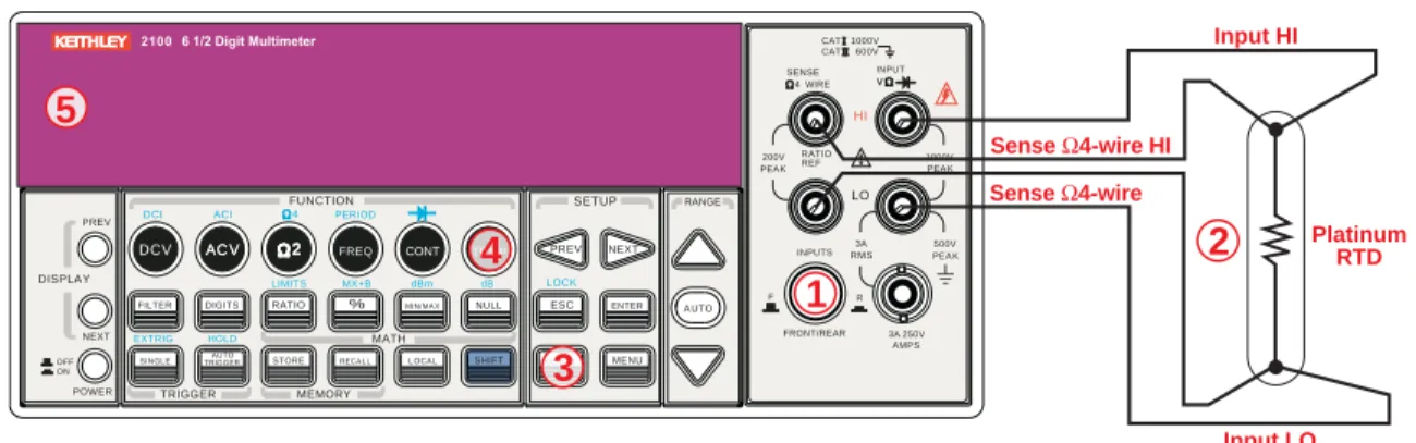
3 Figure 3-1 Model 2100 DC connections... 3-2 Figure 3-2 Model 2100 AC connections... 3-2 Figure 3-3 Model 2100 rear panel input terminals... 3-3 Figure 3-4 Model 2100 current measurement (front panel)... 3-4 Figure 3-5 Model 2100 current measurement... 3-4 Figure 3-6 Model 2100 2-wire resistance... 3-5 Figure 3-7 Model 2100 4-wire resistance... 3-5 Figure 3-8 Model 2100 rear panel 2-wire resistance measurement... 3-5 Figure 3-9 Model 2100 rear panel 4-wire resistance measurement... 3-6 Figure 3-10 Model 2100 2-wire resistance / continuity... 3-7 Figure 3-11 Model 2100 general purpose diode... 3-8 Figure 3-12 Theory diagram of 2-wire RTD measurement... 3-9 Figure 3-13 Theory diagram of 3-wire RTD measurement... 3-9 Figure 3-14 Theory diagram of 4-wire RTD measurement... 3-10
4 Figure 4-1 Setting Auto Zero and Auto Gain from the front panel... 4-3 Figure 4-2 Setting the AC Filter using the front panel... 4-5 Figure 4-3 Front panel resolution... 4-7 Figure 4-4 Front panel DCV... 4-8 Figure 4-5 Front panel threshold resistance... 4-9 Figure 4-6 Front panel auto-range... 4-10 Figure 4-7 Front panel input switch terminals... 4-13 Figure 4-8 Trigger operation flow chart... 4-14 Figure 4-9 Toggle auto triggering on and off... 4-15 Figure 4-10 Single trigger... 4-16 Figure 4-11 Trig submenu... 4-17 Figure 4-12 Reading hold... 4-18 Figure 4-13 Setting delay time from the front panel... 4-19 Figure 4-14 Making a Ratio measurement from the front panel... 4-20 Figure 4-15 Making a percent measurement from the front panel... 4-21 Figure 4-16 Using MIN/MAX from the front panel... 4-22 Figure 4-17 Using the NULL function from the front panel... 4-23 Figure 4-18 Configuring the Limits function from the front panel... 4-24 Figure 4-19 Making a limits test from the front panel... 4-25 Figure 4-20 Using the MX+B function from the front panel... 4-26 Figure 4-21 Setting the relative reference value... 4-27 Figure 4-22 Making a dB measurement from the front panel... 4-27 Figure 4-23 Setting the reference resistance from the front panel... 4-28 Figure 4-24 Making a dBm measurement from the front panel... 4-29 Figure 4-25 The Model 2100 dot-matrix display screen... 4-29 Figure 4-26 Controlling the display from the front panel... 4-30 Figure 4-27 Controlling the beeper from the front panel... 4-31 Figure 4-28 Storing readings from the front panel... 4-32 Figure 4-29 Recalling readings from the front panel... 4-33 Figure 4-30 Adjusting the sensitivity band from the front panel... 4-34 Figure 4-31 Saving or restoring default settings... 4-35 Figure 4-32 Selecting a language... 4-35 Figure 4-33 Checking the error queue... 4-36 Figure 4-34 Checking the firmware revision... 4-37 Figure 4-35 Installing the Model 2100 firmware update ... 4-37 Figure 4-36 The Open dialog box... 4-38 Figure 4-37 Model 2100 firmware upgrade in progress... 4-38 Figure 4-38 Restart device to complete update message... 4-39 Figure 4-39 Viewing calibration information... 4-40
Section Table Title Page
2 Table 2-1 Available voltage setting selectors for local line power requirements 2-6 Table 2-2 Factory default... 2-18 4 Table 4-1 Relationship of resolution to Auto Gain... 4-3 Table 4-2 AC filters default settings... 4-4 Table 4-3 Default factors... 4-11 Table 4-4 Default measurements... 4-18 Table 4-5 Valid values of Save Data... 4-34 5 Table 5-1 USB connector pin out and designations... 5-2 6 Table 6-1 Execution error codes... 6-2
This page left blank intentionally.
General Information
In this section:
Topic Page
Introduction... 1-2 Feature overview... 1-2 Specifications... 1-3 Manual addenda... 1-3 Precautions for operation... 1-3 Upkeep of the Model 2100... 1-3 Safety information... 1-4 Safety symbols and terms... 1-4 Inspection for damage... 1-4 Shipment contents... 1-5 Instruction manual... 1-5 Repacking for shipment... 1-5
Introduction
This section contains general information about the Keithley Instruments Model 2100 6 1/2-Digit Resolution Digital Multimeter. The information is organized as follows:
• Feature overview
• Manual addenda
• Precautions for operation
• Upkeep of the Model 2100
• Safety information
• Inspection for damage
• Shipment contents
• Instruction manual
• Repacking for shipment
If you have any questions after reviewing this information, please contact your local Keithley Instruments representative or call one of our Applications Engineers at 1-888-KEITHLEY (1-888-534-8453). You can also contact us through our website at www.keithley.com.
Feature overview
Figure 1-1
The Model 2100 6 1/2-Digit Resolution Digital Multimeter
The Keithley Instruments Model 2100 is a rugged and versatile 6 1/2-digit resolution digital multimeter. It has 0.003% one-year basic DC voltage accuracy at 10V range and 0.005% one-year basic resistance accuracy at 10kΩ range. At 6 1/2 digits, the multimeter delivers 50 triggered RDGS/sec via the USB remote interface. At the fast 4 1/2-digit setting, it reads over 2000 RDGS/
sec into its internal buffer.
• Resolution: 6 1/2 digits
• 5x7 dot-matrix VFD, dual displays with 3-color annunciators
• Eleven standard measurement functions and eight math functions
• Stability, accuracy, and speed
• Built-in USB interfaces
• DC voltage: 0.1V, 1V, 10V, 100V, and 1000V
• AC voltage: 0.1V, 1V, 10V, 100V, and 750V
• DC current: 10mA, 100mA, 1A, and 3A
• AC current: 1A, and 3A
• Two and 4-wire resistance: 100Ω, 1KΩ, 10KΩ, 100KΩ, 1MΩ, 10MΩ, and 100MΩ
• Frequency: From 3Hz to 300kHz
• Period measurement
• Diode measurement
• Continuity measurement for resistance
Some additional capabilities of the Model 2100 include:
• Temperature measurement using RTDs
• Full math functions: dB, dBm, MX+B, ratio, percentage, Max/Min, null, and limits
• TMC compliant USB remote control interface for PC control
• Microsoft® Office Word, and Excel add-in tools for remotely storing and recalling the measured values from these applications
Specifications
Refer to Appendix A of this manual for complete Model 2100 specifications. Check the Keithley Instruments website at www.keithley.com for the latest updates to the specifications.
Manual addenda
Any improvements or changes concerning the Model 2100 or manual will be explained in an addendum included with the manual. Be sure to note these changes and incorporate them into the manual.
Precautions for operation
• Please carefully read the manual before operating this device.
• This manual is for reference only. Please consult your local service representative for further assistance.
• The contents of this manual may be amended by the manufacturer without notice.
• Never allow unauthorized personnel to dismantle the equipment, or equipment may be damaged.
• The equipment has been strictly tested for quality before delivery from our factory.
• Do not use the meter around explosive gas or flammable vapors.
• The patent and related documents for the equipment belong to Keithley Instruments, Inc.
and may not be used by others without permission.
Upkeep of the Model 2100
• Although the Model 2100 multimeter is very durable and weather resistant, care should be taken not to expose it to severe impacts or forces.
• Keep the Model 2100 away from water and damp environments.
• Calibration should be performed every year. Please contact your local service representative for more information.
• If an incorrect display or abnormal beeps occur, you should stop using the equipment at once and contact your local service representative.
• Wipe the surface of the Model 2100 multimeter with a dry or damp clean cloth to dust and clean any residue from the enclosure.
Safety information
WARNING To avoid possible electric shock, personal injury, or death, please read and follow these guidelines carefully:
• Follow the guidelines in this manual and DO NOT use the meter if the case is damaged. Check the meter case and terminals, and make sure all the devices are in the proper positions.
• Do not apply excessive voltage to the multimeter. Apply voltage within the rated range only.
• Use caution when measuring voltages above 30V RMS, 42V peak, or 60V DC.
Higher voltages pose an electric shock hazard.
• When using the probes, always keep your fingers behind the finger guards.
• Always connect the common test leads (black) before connecting the live test leads (red), and disconnect the live test leads (red) before disconnecting the common test leads (black). This will reduce the chance of an electric shock.
• Disconnect circuit power and discharge all high-voltage capacitors before testing resistance, continuity, diodes, or capacitance.
• Repairs must only be performed by qualified service personnel.
• When replacing fuses, use only the same type and same rating as specified.
Make sure the unit is disconnected from AC power and any external signals first.
• Do not try to operate the meter if it is damaged. Disconnect the power from the equipment and consult your local service representative. Return the product to a Keithley Instruments service facility if necessary.
Safety symbols and terms
The following symbols and terms may be found on the Model 2100 or used in this manual.
The symbol indicates that the user should refer to the operating instructions located in the manual.
The symbol shows that high voltage may be present on the terminal(s). Use standard safety precautions to avoid personal contact with these voltages.
Inspection for damage
The Model 2100 was carefully inspected electrically and mechanically before shipment. After unpacking all items from the shipping carton, check for any obvious signs of physical damage that may have occurred during transit. Report any damage to the shipping agent immediately. Save the original packing carton for possible future shipment.
!
Shipment contents
The following items are included with every Model 2100 order:
• One Model 2100 Multimeter unit (112mm/4.4in (H) x 256mm/10.1in (W) x 375/14.75in (D), 4.1Kg/9lbs)
• One power line cord
• One USB cable
• Standard safety test leads
• One CD-ROM (including this electronic User's Manual and software applications)
Instruction manual
A CD-ROM containing this User’s Manual and required software and drivers is included with each Model 2100 order.
Check the Keithley Instruments website at www.keithley.com for the latest revision of the manual.
The latest manual can be downloaded (in PDF format) from the website.
Repacking for shipment
Should it become necessary to return the Model 2100 for repair, carefully pack the unit in its original packing carton or the equivalent, and follow these instructions:
• Call the Repair Department at 1-888-KEITHLEY (1-888-534-8453) for a Return Material Authorization (RMA) number.
• Advise as to the warranty status of the Model 2100.
• Write ATTENTION REPAIR DEPARTMENT and the RMA number on the shipping label.
Complete and include the Service Form located at the back of this manual.
This page left blank intentionally.
Getting Started
In this section:
Topic Page
Overview... 2-2 Setting up the Model 2100 Digital Multimeter... 2-2 Adjusting the handle... 2-2 Setting the line voltage... 2-4 Connecting the power... 2-7 Changing the fuses... 2-9 Factory default settings... 2-18 Model 2100 familiarization... 2-19 The front panel... 2-19 The display... 2-21 The rear panel... 2-23
Overview
This section will give you an overview of the Keithley Instruments Model 2100 6 1/2-Digit Resolution Multimeter’s basic features and guide you through the basics of the Model 2100.
Setting up the Model 2100 Digital Multimeter
The purpose of this section is to prepare you to use the Model 2100 Digital Multimeter (DMM). You should check whether you have all the parts needed to operate your multimeter. All Keithley Instruments products are handled and inspected professionally before shipping out to our customers. If you find any damaged or missing parts, please contact your local service
representative immediately. Do not attempt to operate a damaged product; if you have any doubt about the condition of your Model 2100, please contact your local service representative.
Adjusting the handle
You may adjust the carrying handle to suit your needs. Figures 2-1, 2-2, 2-3, 2-4, and 2-5 show you how to adjust the handle.
Removing the handle
Step 1: Move the handle to an upright position.
Pull slightly outward on both sides of the handle, and slowly rotate it up as shown in Figure 2-1.
Figure 2-1
Moving the handle to an upright position
Step 2: Remove the handle
When the handle is turned up to a 90° angle with the multimeter, pull it away from the multimeter (refer to Figure 2-2).
Figure 2-2
Removing the handle from the multimeter
Adjusting the handle position
You can adjust the Model 2100’s handle to suit your needs:
Position 1: Default
The default position is used for packing the Model 2100 (refer to Figure 2-3).
Figure 2-3
Default handle position
Position 2: Operating
The adjusted handle position shown in Figure 2-4 is for multimeter operation.
FILTER
NEXT PREV
DIGITS RATIO % MIN/MA X NULL ESC ENTER A UTO
SINGL E TRIGGERAUT O STORE RECA L L L OCA L SHIFT CONFIG MENU DCV AC V 22 FREQ CONT TEMP
4 WIRE
RATIO V INPUT
PEA K 200V PEA K
HI
LO
PEA K 500V 3A RMS INPUTS
3A 250V FRONT/REAR
AMP S R
1000V REF
CAT1000V CAT600V
LOCK SETUP
AC V 22 FUNCT ION
DCI ACI 4 PERIOD
LIMIT S MX+B dB
EXTRIG HOLD MATH
TRIGGER MEMORY
dBm
RANGE
DISPLAY
NEXT PREV
POWER OFF ON
SENSE
F
Figure 2-4
Operation handle position
Position 3: Carrying
The carrying position is shown in Figure 2-5.
Figure 2-5
Carrying position
Setting the line voltage
WARNING Before changing the setting, ensure that the multimeter is disconnected from the AC power.
Step 1: Disconnect AC power
Verify that the meter is disconnected from AC power as shown in Figure 2-6.
Figure 2-6
Disconnecting AC power
Step 2: Open the voltage setting selector
Open the voltage setting selector cap as shown in Figure 2-7 (a flat blade screwdriver may be required).
Figure 2-7
Opening the voltage setting selector
Step 3: Remove the red voltage setting selector
Remove the red voltage selector fuse holder from the right middle seam as shown in Figure 2-8 (a flat blade screwdriver may be required).
Figure 2-8
Removing the red voltage selector fuse holder
Step 4: Change the voltage setting
Turn the voltage setting to the correct setting.
NOTE To accommodate differing local area power requirements, Keithley Instruments has three available models of voltage setting selectors for the Model 2100 (each with two voltage settings). The voltage setting selector included with your Model 2100 should have the appropriate voltage settings for your area's line power requirements. If you do not have the correct voltage setting selector, please contact your local Keithley Instruments representative to request the correct model (see Table 2-1, below).
Step 5: Insert the voltage selector
Insert the voltage setting selector back into the socket and close the cap as shown in Figure 2-9.
Table 2-1
Available voltage setting selectors for local line power requirements
Model number Voltage select options Voltage set to:
2100/120 120/240 120
2100/230-240 120/240 240
2100/220 120/220 220
Figure 2-9
Inserting the voltage selector
Connecting the power
Power-off the multimeter
Ensure that the power switch on the front panel is in the "POWER OFF" position before plugging the Model 2100 in (refer to Figure 2-10).
Figure 2-10
Powering-off the multimeter
Plug-in the power cord
After finishing the above procedures, you can plug-in your power cord as shown in Figure 2-11.
FILTER
NEXT PREV
DIGITS RATIO % MIN/MA X NULL ESC ENTER A UTO
SINGL E TRIGGERAUT O STORE RECA L L L OCA L SHIFT CONFIG MENU DCV AC V 22 FREQ CONT TEMP
4 WIRE
RATIO V INPUT
PEA K 200V
PEA K HI
LO
PEA K 500V 3A INPUTS RMS
3A 250V FRONT/REAR
AMP S R
1000V REF
CAT1000V CAT 600V
LOCK SETUP
AC V 22 FUNCTION
DCI ACI 4 PERIOD
LIMIT S MX+B dB
EXTRIG HOLD MATH
TRIGGER MEMORY
dBm
RANGE
DISPLAY
NEXT PREV
POWER OFF ON
SENSE
F
Figure 2-11
Plugging in the power cord
Switch the power on
Press the power switch on the front panel to activate the Model 2100 as shown in Figure 2-12.
Figure 2-12
Switching on the power
Check the power-line voltage on the rear panel to see if the voltage setting is correct for your area.
Change the setting if it is not correct by following the steps in “Setting the line voltage” later in this section.
FILTER
NEXT PREV
DIGITS RATIO % MIN/MA X NULL ESC ENTER A UTO
SINGL E TRIGGERAUT O STORE RECA L L L OCA L SHIFT CONFIG MENU DCV AC V 22 FREQ CONT TEMP
4 WIRE
RATIO V INPUT
PEA K 200V
PEA K HI
LO
PEA K 500V 3A INPUTS RMS
3A 250V FRONT/REAR
AMP S R
1000V REF
CAT1000V CAT 600V
LOCK SETUP
AC V 22 FUNCTION
DCI ACI 4 PERIOD
LIMIT S MX+B dB
EXTRIG HOLD MATH
TRIGGER MEMORY
dBm
RANGE
DISPLAY
NEXT PREV
POWER OFF ON
SENSE
F
WARNING Before connecting power to the Model 2100, ensure that the fuse is intact.
Refer to “Changing the fuses” later in this section if the fuse is open/blown.
WARNING The main power input voltage to the unit must be selected correctly according to the local installation’s power supply. Check the voltage indication window on the power module at the back of the unit to verify the voltage setting is correctly set. If the voltage is not correctly set, refer to “Setting the line voltage” below.
WARNING The power cord supplied with the Model 2100 contains a separate ground wire for use with grounded outlets. When proper connections are made, the instrument chassis is connected to power line ground through the ground wire in the power cord. Failure to use a grounded outlet may result in personal injury or death due to electric shock.
Changing the fuses
WARNING Before replacing the power-line fuse or current input fuses, verify that the multimeter is disconnected from AC power. You must be qualified personnel to perform this action.
CAUTION For continued protection against fire or instrument damage, only replace the fuses with the same type and rating. If the instrument repeatedly blows fuses, have the unit serviced at an authorized repair facility.
Power line fuse
A power-line fuse located next to the AC receptacle (in the voltage setting selector) protects the power line input of the instrument. Verify that the power-line fuse is good and replace it with a new one if it is damaged. The Model 2100 is shipped from the factory with a 0.25A/250V, 5×20mm slow-blow glass fuse installed (Keithley Instruments part number FU-96-4). This is the correct fuse type for all line voltage settings; use only this type of replacement fuse.
To change the power line fuse:
Step 1: Disconnect the AC power
Verify that the meter is disconnected from AC power as shown in Figure 2-13.
Figure 2-13
Disconnecting the AC power
Step 2: Open the voltage setting selector
Open the voltage setting selector cap as shown in Figure 2-14 (you will need a screwdriver to do so).
Figure 2-14
Opening the voltage setting selector
Step 3: Remove the red voltage setting selector
Remove the red voltage setting selector from the right middle seam as shown in Figure 2-15 (you might need a screwdriver to do so).
Figure 2-15
Removing the red voltage setting selector
Step 4: Remove the damaged power line fuse
Remove the damaged fuse from the selector as shown in Figure 2-16.
Figure 2-16
Removing the damaged power line fuse
Step 5: Replace the power line fuse
Replace with the new fuse as shown in Figure 2-17.
Figure 2-17
Replacing the fuse
Step 6: Reinsert the voltage selector
Insert the voltage setting selector back into the socket and close the cap as shown in Figure 2-18.
CAUTION Verify that the correct voltage setting appears in the red voltage selection window in the power module before powering up the unit. Refer to
“Connecting the power” earlier in this section for instructions on how to correctly power up the unit.
Figure 2-18
Reinserting the voltage selector
Current input fuses
The Model 2100 has two 3A fuses in the front and rear current input terminals, and an additional 7A fuse in series with either the front or rear current input fuse (depending on the front or rear panel switch position) for added protection against a strong current pulse. If a strong current pulse overloads the 7A fuse, it will blow quickly, thus saving the 3A fuse and the instrument's internal circuitry (see Figure 2-19).
Figure 2-19
Current protection using 3A and 7A current input fuses in series
The two main fuses located in the front and rear current input terminals of your Model 2100 are 3A, 250V, 5x20mm fast-acting glass fuses (Keithley Instruments part number FU-99-1). The additional current input fuse is a 7A, 250V, 5x20mm fast-acting ceramic tube fuse. See the following text for instructions on how to replace these fuses if they become damaged.
To change the 3A front or rear panel current input terminal fuses:
WARNING Before replacing the power line fuse or current input fuses, verify that the multimeter is disconnected from AC power. You must be qualified personnel to perform this procedure.
CAUTION For continued protection against fire or instrument damage, only replace the fuses with the same type and rating. If the instrument repeatedly blows fuses, have the unit serviced at an authorized repair facility.
NOTE Instructions for replacing the front panel current input terminal fuse are depicted here; the rear panel current input terminal fuse can be changed using the same procedure.
Step 1: Disconnect the AC power
Verify that the meter is disconnected from AC power, as shown in Figure 2-20.
Figure 2-20
Disconnecting the AC power
Step 2: Release the current input terminal fuse holder
Push the current input terminal in and turn it to the right (see Figure 2-21) to release it.
Figure 2-21
Releasing the current input terminal fuse holder
Step 3: Remove the current input terminal fuse holder
Gently pull out the current input terminal fuse holder to expose the current input fuse (see Figure 2-22).
Figure 2-22
Removing the current input terminal fuse holder
Step 4: Remove and replace the damaged fuse
Remove the damaged fuse and replace it with the same type and rating of fuse (see Figure 2-23).
Figure 2-23
Removing and replacing the damaged fuse
Step 5: Reinsert and secure the current input terminal fuse holder
Reinsert the current input terminal fuse holder, turning it to the left as you push it in (see Figure 2-24). Ensure that the fuse holder is properly seated and secured.
Figure 2-24
Reinserting and securing the current input terminal fuse holder
WARNING Before reconnecting the power line cord to your multimeter, make sure that the power switch is in the "POWER OFF" position.
To change the 7A current input fuse on the rear panel:
Step 1: Disconnect the AC power
Verify that the meter is disconnected from AC power, as shown in Figure 2-25.
Figure 2-25
Disconnecting the AC power
Step 2: Release the current input terminal fuse holder
Using a flat-blade screwdriver, turn the 7A current input fuse holder on the rear panel to the left until it is released (see Figure 2-26).
Figure 2-26
Releasing the 7A current input fuse holder on the rear panel
Step 3: Remove the current input terminal fuse holder
Gently pull out the current input terminal fuse holder to expose the 7A current input fuse (see Figure 2-27).
Figure 2-27
Removing the 7A current input terminal fuse holder
Step 4: Remove and replace the damaged fuse
Remove the damaged fuse and replace it with the same type and rating of fuse (see Figure 2-28).
Figure 2-28
Removing and replacing the damaged fuse
Step 5: Reinsert and secure the 7A current input terminal fuse holder
Reinsert the 7A current input terminal fuse holder, turning it to the right as you push it in (see Figure 2-29). Ensure that the fuse holder is properly seated and secured.
Figure 2-29
Reinserting and securing the 7A current input terminal fuse holder
WARNING Before reconnecting the power line cord to your multimeter, ensure that the power switch is in the "POWER OFF" position.
Factory default settings
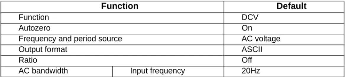
Table 2-2 shows the factory default settings for the Model 2100.
Table 2-2 Factory default
Function Default
Function DCV
Autozero On
Frequency and period source AC voltage
Output format ASCII
Ratio Off
AC bandwidth Input frequency 20Hz
Model 2100 familiarization
The Model 2100 6 1/2-Digit Resolution Digital Multimeter consists of three major parts: the front panel, the display, and the rear panel. Following is a discussion of these components.
The front panel
The keys and terminals on the front panel are divided into the following groups (refer to Figure 2-30):
• DISPLAY and POWER
• FUNCTION, MATH, TRIGGER, MEMORY, SETUP, RANGE, and INPUT TERMINALS
• FILTER, DIGITS, LOCAL, and SHIFT
Voltage AC digits 5.5
DC digits Slow 5.5 (1 PLC)
Range Auto
Current AC digits 5.5
DC digits slow 5.5 (1 PLC)
Range Auto
Frequency and period AC digits 5.5
Range Auto
Rate Medium (100ms)
Diode Test Digits 5.5
Range 1mA
Rate 0.1 PLC
Resistance (2-wire) Digits Slow 5.5 (1 PLC)
Range Auto
Triggers Source Immediate
Delay Auto
Input Resistance 10MΩ
Table 2-2 Factory default
Function Default
Function DCV
Figure 2-30
Front panel keys and terminals
1. DISPLAY and POWER keys:
i. DISPLAY: Shows model, version and condition by pressing the PREV and NEXT keys
ii. POWER: Activates the Model 2100 digital multimeter
2. FUNCTION keys:
a. First row without SHIFT key:
i. DCV: Selects DC voltage measurement ii. ACV: Selects AC voltage measurement iii. Ω2: Selects 2-wire resistance measurement iv. FREQ: Selects frequency measurement v. CONT: Selects the continuity test
b. First row with SHIFT key:
i. DCI: Selects DC current measurement ii. ACI: Selects AC current measurement iii. Ω4: Selects 4-wire resistance measurement iv. PERIOD: Selects period measurement
v. : Selects diode testing
c. Second row without SHIFT key:
i. FILTER: Enables or disables the digital filter ii. DIGITS: Changes the resolution
iii. RATIO: Enables the dcv:dcv ratio function
iv. %: Calculates the ratio to a target value in percentage
v. MIN/MAX: Captures the minimum or maximum readings from the measurement vi. NULL: Activates the offset function in order to get the real measured reading
d. Second row with SHIFT key:
i. LIMITS: Used for setting upper and lower limit values for readings
ii. MX+B: Used for calculating slope. X is the normal display reading; M and B are constants specified by user for scale factor and offset
iii. dBm: Used for displaying voltage measurement in dBm power unit iv. dB: Used for displaying voltage measurement in decibel unit
e. Third row without SHIFT key:
FILTER
NEXT PREV
DIGITS RATIO % MIN/MA X NULL ESC ENTER A UTO
SINGL E TRIGGERAUTO STORE RECA L L L OCA L SHIFT CONFIG MENU
DCV AC V 22 FREQ CONT TEMP
4 WIRE
RATIO V INPUT
PEA K 200V
PEA K HI
LO
PEA K 500V 3A
INPUTS RMS
3A 250V FRONT/REAR
AMP S R
1000V REF
CAT 1000V CAT 600V
LOCK SETUP
AC V 22
FUNCTION
DCI ACI 4 PERIOD
LIMIT S MX+B dB
EXTRIG HOLD MATH
TRIGGER MEMORY
dBm
RANGE
DISPLAY
NEXT PREV
POWER OFF ON
SENSE
1
F5 4
3
2
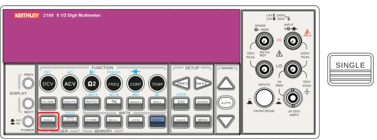
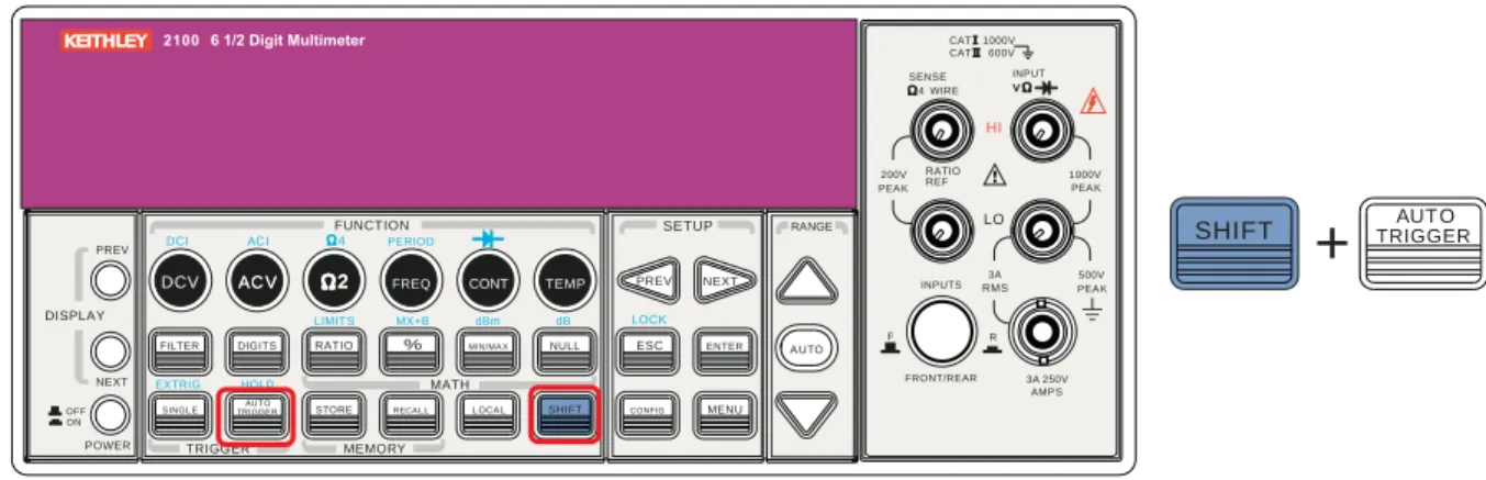
i. SINGLE: Manually triggers the multimeter to make measurements
ii. AUTO TRIGGER: Instructs the multimeter to make measurements continuously iii. STORE: Stores a specified number of subsequent readings
iv. RECALL: Displays stored readings. Use the left and right
arrow keys or the up and down arrow keys to toggle between reading number and reading
v. LOCAL: Cancels USB remote mode
vi. SHIFT (in blue): Used to select functions that appear on keys in blue uppercase text
f. Third row with SHIFT key:
i. EXTRIG: Selects external triggers as the trigger source via BNC port on the rear panel
ii. HOLD: Holds a reading
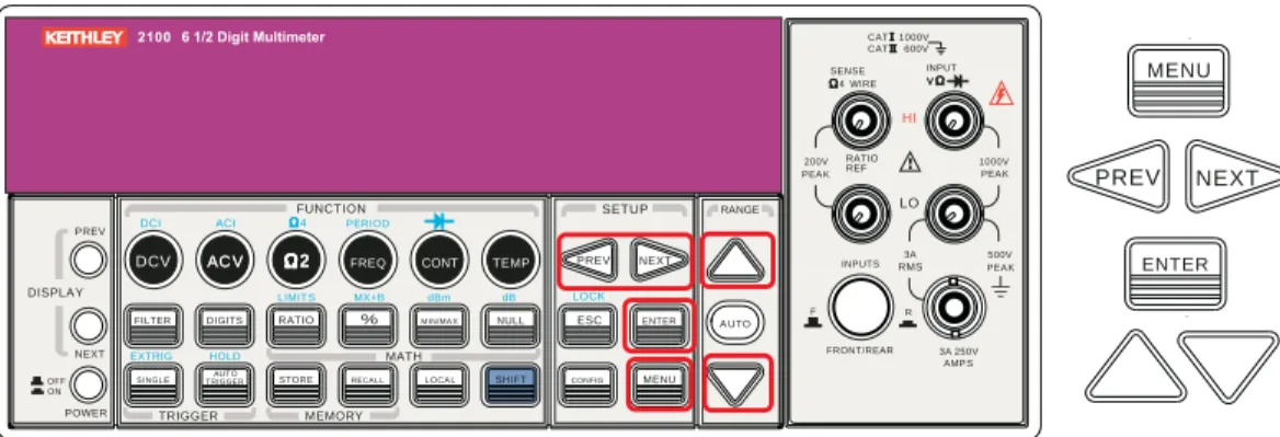
3. SETUP keys:
a. First row in SETUP section:
i. : Scrolls through the buffer, conceals or reveals the digits while measuring
b. Second row in SETUP section:
i. ESC: Cancels selection, moving back to the measurement display
ii. ENTER: Accepts selection, moving to next choice or back to the measurement display
iii. LOCK: Press SHIFT then ESC key to prevent unpredictable operation on the panel; to release the lock condition, press ESC again
c. Third row in SETUP section:
i. CONFIG: Allows setting or adjustment functions relating to some front panel keys ii. MENU: Allows setting or adjustment functions not relating to other front panel
keys
4. RANGE keys:
i. : Moves to higher range ii. : Moves to lower range
iii. AUTO: Enables or disables auto-range
5. INPUTS (TERMINALS) toggle button, FUSE device connection, and inserted connections:
i. : TERMINALS toggle button: Selects input signal
connections on front or rear panel
ii. Input HI and LO: Used for DCV, ACV, O2, CONT, FREQ, PERIOD, and RTD temperature measurements
AMPS: Used with INPUT LO for DCI and ACI measurements; also holds current fuse for front panel amps input
SENSE HI and LO: Used with INPUT HI and LO for O4 and RTD temperature measurements
iii. LO and I: Used for making DC and AC current measurements
iv. Front FUSE: Secures your meter against damage by strong current pulses (maximum current: 3A, 250V)
The display
The Model 2100 has a 5x7 character dot-matrix, dual-line display with three-color (white, red, and yellow) annunciators for easy viewing. There are two rows in the dual-display screen. The upper row displays both readings and measurement units. A maximum of 13 characters is possible for the upper row dot-matrix display. The lower row displays the range of the measurements and conditions, or information about the current configuration. A maximum of 16 characters is possible
for the lower row dot-matrix display. There are additional annunciators above and on the right side of the display screen that indicate the state or condition of an ongoing measurement. They are explained individually in the following sections.
Figure 2-31 The display
Annunciators at the top
Figure 2-32
Annunciators at the top
• RMT (REMOTE): Indicates the remote state (USB Interface)
• MAN: Indicates the manual range mode is selected
• TRIG: Shows that single triggering is enabled
• HOLD: Indicates reading hold function is enabled
• MEM: Indicates the use of internal reading memory
• RATIO: Indicates the dcv:dcv ratio operation
• MATH: Indicates the MATH operation is enabled
• ERR: Error occurred
• SHIFT: Indicates the SHIFT button was pressed
• REAR: The rear panel input terminal is selected for the measurement
• FILT: The digital filter is enabled
• 4W: Indicates remote sense
• EXT: Indicates external trigger
Annunciators on the right
• 4W: Indicates 4-wire mode is selected for resistance measurement
• : Indicates that continuity testing is enabled
• : Indicates the diode testing operation was initiated
• EXT: Indicates the External Trigger mode is been enabled
• LOCK: Indicates the front panel menu operation is locked
• OFF: Indicates the front panel display is turned off Figure 2-33
Annunciators on the right
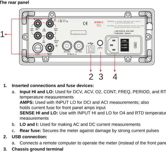
The rear panel
The rear panel of the Model 2100 is shown in Figure 2-34. This figure includes important abbreviated information that should be reviewed before using the instrument.
Figure 2-34 The rear panel
1. Inserted connections and fuse devices:
a. Input HI and LO: Used for DCV, ACV, O2, CONT, FREQ, PERIOD, and RTD temperature measurements
AMPS: Used with INPUT LO for DCI and ACI measurements; also holds current fuse for front panel amps input
SENSE HI and LO: Use with INPUT HI and LO for O4 and RTD temperature measurements
b. LO and I: Used for making AC and DC current measurements
c. Rear fuse: Secures the meter against damage by strong current pulses
2. USB connection:
a. Connects a remote computer to operate the meter (instead of the front panel control) 3. Chassis ground terminal
4. Power module:
CAT1000V CAT 600V
LINE 120V 120V 240V 240V
240V240V
* Tw 00 00 10 00 *
MA DE IN TA IWA N
NO INTERNA L SERVICEA B L E PA RTS, SERVICE WA RNING
B Y QUA L IFIED PERSONNEL ONLY.
FOR CONTINUED PROTECTION A GA INST FIRE HA ZA RD.
CA UTION:
REPL A CE FUSE WITH SA ME TYPE A ND RATING.
1
4
3
2
a. Contains the AC line receptacle, power line fuse, and line voltage setting
• Configured for line voltages of 120/220V or 120/240V (depending on the power utility in your area)
Basic Measurement Functions
In this section:
Topic Page
Introduction... 3-2 Voltage measurements (DC and AC)... 3-2 How to measure voltage... 3-3 Current measurements (DC and AC)... 3-3 How to measure current... 3-3 Resistance measurements (2- and 4-wire)... 3-4 How to measure resistance... 3-6 Frequency and period measurements... 3-6 How to measure frequency and period... 3-6 Continuity measurements... 3-7 How to measure the continuity... 3-7 Diode measurements... 3-7 How to measure a diode... 3-8 RTD measurements... 3-8 2-wire RTD measurements... 3-8 3-wire RTD measurements... 3-9 4-wire RTD measurements... 3-10
Introduction
This section introduces some basic measurement functions of the Keithley Instruments Model 2100 6 1/2-Digit Resolution Digital Multimeter®. You will learn how to use the Model 2100 multimeter to measure voltage, current, resistance, frequency, period, continuity, and diode forward voltage.
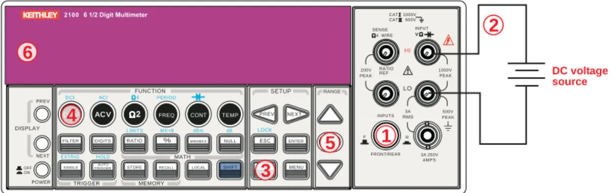
Voltage measurements (DC and AC)
The ranges for DC voltage (DCV) measurements for the Model 2100 are 100mV, 1V, 10V, 100V, and 1000V. For AC voltage (ACV) measurements, the ranges are 100mV to 750V RMS, or 1000V peak. Figures 3-1 and 3-2 show the locations of the keys needed and message displays for voltage measurement. Figure 3-3 shows the location of the input terminals on the rear panel.
WARNING Do not apply more than 1000V (peak) to the Model 2100 multimeter. Applying excess voltage may damage your meter or cause possible electric shock, resulting in personal injury or death.
NOTE To eliminate the thermal EMFs due to the differences between two metals, use copper leads to connect your source signal to the meter.
Figure 3-1
Model 2100 DC connections
Figure 3-2
Model 2100 AC connections
FILTER
PREV NEXT
DIGITS RATIO % MIN/MA X NULL ESC ENTER A UTO
SINGL E TRIGGERAUTO STORE RECA L L L OCA L SHIFT CONFIG MENU
DCV AC V 22 FREQ CONT TEMP
4 WIRE
RATIO V INPUT
PEA K 200V
PEA K HI
LO
PEA K 500V 3A INPUTS RMS
3A 250V FRONT/REAR
AMP S R
1000V REF
CAT1000V CAT 600V
LOCK SETUP
AC V 22 FUNCTION
DCI ACI 4 PERIOD
LIMIT S MX+B dB
EXTRIG HOLD MATH
TRIGGER MEMORY
dBm
RANGE
DISPLAY
NEXT PREV
POWER OFF ON
SENSE
F
CONFIG
3
2
1
DCV
4
A UTO
5 6
DC voltage source
Input resistance = 10MΩ on 1000V and 100V ranges:
> 10GΩ on 10V, 1V, and 100mV ranges.
FILTER
PREV NEXT
DIGITS RATIO % MIN/MA X NULL ESC ENTER A UTO
SINGL E TRIGGERAUTO STORE RECA L L L OCA L SHIFT CONFIG MENU
DCV AC V 22 FREQ CONT TEMP
4 WIRE
RATIO V INPUT
PEA K 200V
PEA K HI
LO
PEA K 500V 3A INPUTS RMS
3A 250V FRONT/REAR
AMP S R
1000V REF
CAT1000V CAT 600V
LOCK SETUP
AC V 22 FUNCTION
DCI ACI 4 PERIOD
LIMIT S MX+B dB
EXTRIG HOLD MATH
TRIGGER MEMORY
dBm
RANGE
DISPLAY
NEXT PREV
POWER OFF ON
SENSE
F
CONFIG
3
2
1
AC V AC V
4
A UTO
5 6
AC voltage source
Input Impedence = 1MΩ in parallel with < 100pF
(Warning: Maximum input = 750V RMS, 1000V peak, 8x10’ V-Hz)
Figure 3-3
Model 2100 rear panel input terminals
NOTE Follow the same procedure when using either the front or rear panel terminals (refer to Figure 3-3).
How to measure voltage
1. Select input signal connections on front or rear panel.
2. Connect the test leads to the terminals as shown in Figure 3-1 (DC) or Figure 3-2 (AC).
3. Set the resolution of DCV (refer to “Resolution setting (digits)” in Section 4), bandwidth of ACV (refer to “AC filter” in Section 4) or skip this step if the default settings are used.
4. Press the DCV or ACV key for DC or AC voltage measurement.
5. Select the auto-range function by pressing the AUTO key on the front panel, or use the up and down arrow keys to select the desired range.
6. Connect the test leads to your source signal and observe the reading shown on the display.
If the input signal is beyond the allowed range, an overflow message ("OVLD") will be displayed.
Current measurements (DC and AC)
The ranges for DC current measurements for the Model 2100 are 10mA, 100mA, 1A, and 3A, with a sensitivity of 10NA. For AC current measurements, the range is 1A to 3A RMS with a sensitivity of 10
μ
A. Figures 3-4 and 3-5 illustrate how to measure DC/AC currents with the Model 2100.CAUTION The maximum input current allowed is 3A, 250V. Do not apply excess current to your meter to avoid damaging the fuse of current input.
How to measure current
1. Select input signal connections on front or rear panel.
2. Connect the test leads to the terminals as shown in Figure 3-4.
3. Set the resolution of DCI (refer to “Resolution setting (digits)” in Section 4), and bandwidth of ACI (refer to “AC filter” in Section 4), or skip this step if the default setting is used.
4. Press SHIFT + DCV or SHIFT + ACV keys for DCI or ACI measurement.
5. Select the auto-range function by pressing the AUTO key on the front panel, or use the up and down arrow keys to select the desired range.
6. Connect test leads to your source signal and observe the reading shown on the display. If the input signal is greater than the allowed range, an overflow message ("OVLD") will be displayed.
AC VM
CAT1000V CAT 600V
LINE 120V 120V 240V 240V
240V240V
* Tw 00 00 10 00 *
MA DE IN TA IWA N
NO INTERNA L SERVICEA B L E PA RTS, SERVICE WA RNING
B Y QUA L IFIED PERSONNEL ONLY.
FOR CONTINUED PROTECTION A GA INST FIRE HA ZA RD.
CA UTION:
REPL A CE FUSE WITH SA ME TYPE A ND RATING.
DC VM
or
VM = Voltage measurement