Veröffentlichungen der DGK
Ausschuss Geodäsie der Bayerischen Akademie der Wissenschaften
Reihe C Dissertationen Heft Nr. 790
Michael Mink
Performance
of Receiver Autonomous Integrity Monitoring (RAIM) for Maritime Operations
München 2017
Verlag der Bayerischen Akademie der Wissenschaften
ISSN 0065-5325 ISBN 978-3-7696-5202-4
Veröffentlichungen der DGK
Ausschuss Geodäsie der Bayerischen Akademie der Wissenschaften
Reihe C Dissertationen Heft Nr. 790
Performance
of Receiver Autonomous Integrity Monitoring (RAIM) for Maritime Operations
Zur Erlangung des akademischen Grades eines Doktor-Ingenieurs (Dr.-Ing.)
von der Fakultät für Bauingenieur-, Geo- und Umweltwissenschaften des Karlsruher Instituts für Technologie (KIT)
genehmigte Dissertation
Vorgelegt von
Dipl.-Ing. Michael Mink
aus Rottweil
München 2017
Verlag der Bayerischen Akademie der Wissenschaften
ISSN 0065-5325 ISBN 978-3-7696-5202-4
Adresse der DGK:
Ausschuss Geodäsie der Bayerischen Akademie der Wissenschaften (DGK)
Alfons-Goppel-Straße 11 ! D – 80539 München Telefon +49 – 89 – 230311113
e-mail post@dgk.badw.de ! http://www.dgk.badw.de
Hauptreferent: Prof. Dr.-Ing. Dr. h. c. Bernhard Heck, Geodätisches Institut,
Karlsruher Institut für Technologie Korreferent: PD Dr.-Ing. habil. Jan Wendel,
Institut für Theoretische Elektrotechnik und Systemoptimierung, Karlsruher Institut für Technologie
Tag der mündlichen Prüfung: 27.07.2016
Diese Dissertation ist auf dem Server der DGK unter <http://dgk.badw.de/>
sowie auf dem Servern des Karlsruher Institut für Technologie (KIT) unter <https://publikationen.bibliothek.kit.edu/1000063350>
und der Deutschen Nationalbibliothek (NB) unter <http://d-nb.info/1122461410/34>
elektronisch publiziert
© 2017 Bayerische Akademie der Wissenschaften, München
Alle Rechte vorbehalten. Ohne Genehmigung der Herausgeber ist es auch nicht gestattet,
die Veröffentlichung oder Teile daraus auf photomechanischem Wege (Photokopie, Mikrokopie) zu vervielfältigen.
ISSN 0065-5325 ISBN 978-3-7696-5202-4
3
Kurzfassung
Die Anwendung von Globalen Satellitengestützten Navigationssystemen (GNSS) hat sich in der heutigen Zeit auf dem Gebiet der maritimen Navigation durchgesetzt und kommt dabei weltweit zur Anwendung. Hierbei gibt es Anwendungen, die als sicherheitskritisch eingestuft und für die entsprechende Anforderungen an das GNSS gestellt werden. Die International Maritime Organisation (IMO) hat für verschiedenste Anwendungsbereiche Anforderungen hinsichtlich verschiedener Parameter definiert und veröffentlicht. Eine entscheidende Rolle spielt hierbei die Integrität einer GNSS-gestützten Positionslösung: die Integrität stellt ein Maß für die Vertrau- enswürdigkeit einer Positionslösung dar. Zudem beinhaltet der Begriff der Integrität die Fähigkeit den Nutzer rechtzeitig zu warnen, falls das System nicht den jeweiligen Anforderungen genügt. Als weiterer Performance- relevanter Parameter ist die Kontinuität zu nennen: die Kontinuität gibt an, mit welcher Wahrscheinlichkeit das System – für die Dauer der jeweiligen Operation – innerhalb der Spezifikation agiert.
Den bedeutendsten Anwenderkreis im Zusammenhang mit der GNSS-Integrität bildet jedoch die Luftfahrt. Deren sicherheitskritische Anwendungen, die sehr stark auf GNSS angewiesen sind, waren in der Vergangenheit und sind bis heute die Treiber für sämtliche Entwicklungen auf dem Gebiet der GNSS-Integrität. Diese Aussage wird unterstützt durch die Tatsache, dass beispielsweise das Integritätskonzept des europäischen satelliten-basierten Augmentierungssystem EGNOS im Jahre 2011 von der Internationalen zivilen Luftfahrtbehörde (ICAO) zertifi- ziert wurde. Eine Erweiterung der Fähigkeiten von EGNOS ist zeitnah zu erwarten, wenn das System für LPV-200 Operationen – mit erhöhten Anforderungen – freigegeben wird. Vergleichbare Anstrengungen werden zurzeit nicht von der maritimen Anwenderseite unternommen. Der starke Fokus auf sicherheitskritische Luftfahrtan- wendungen spiegelt sich auch sehr deutlich in der aktuellen Literatur wider. Daraus ergibt sich die Tatsache, dass Bedingungen, die für die Luftfahrt relevant sind, besser verstanden sind als für die Schifffahrt. Diese Bedin- gungen beinhalten vor allem die Fehlermodelle für die einzelnen Fehlerbeiträge, die sich auf die Positionsgenau- igkeit auswirken. Außerdem ist das Verständnis der Gefahren, die aus einer Fehlfunktion des GNSS resultieren, viel weiter ausgereift. Diese Gefahren müssen in den Simulationen mit einkalkuliert werden, um der Realität Rechnung zu tragen.
In dieser Arbeit werden zwei Nutzergruppen betrachtet, die zusammen einen Großteil der maritimen Anwen- dungen abdecken. Die „Ocean“ und „Coastal“ Operationen heben sich gegenüber den Anwendungen „Port Ap- proach and Restricted Waters“ insofern ab, als dass keine Anforderungen für die Kontinuität spezifiziert sind. Die Kontinuität für letztere Anwendung ist über einen Zeitraum von 3 Stunden definiert, was sich deutlich im Ver- gleich zur Luftfahrt unterscheidet. Diese genannte Zeitdauer wird auch als Expositionsdauer bezeichnet. Auch gibt es aktuelle Anregungen aus diversen Veröffentlichungen die stringenten Kontinuitätsanforderungen zu vereinfachen, indem die Expositionsdauer von 3 Stunden auf 15 Minuten reduziert wird. Um dieser Entwicklung Rechnung zu tragen und zu antizipieren, werden in der vorliegenden Arbeit beide Expositionszeiten berücksich- tigt. Für beide Nutzergruppen gibt es keine Anforderung bezüglich der vertikalen Positionskomponente.
4 Kurzfassung
Somit zeigen sich signifikante Unterschiede zwischen maritimen und aeronautischen Nutzern in den für die jeweiligen an das GNSS gestellten Anforderungen. Daraus lässt sich die Notwendigkeit einer Überprüfung und gegebenenfalls einer Anpassung der Algorithmen und der damit verbundenen Annahmen ableiten. Eine An- strengung, die sich durch die ganze Arbeit zieht, ist die Überprüfung der Annahmen, die für die Luftfahrt getrof- fen werden, hinsichtlich der Übertragbarkeit auf den maritimen Nutzer. Dabei wird unter anderem der Schluss gezogen, dass nicht alle Fehlermodelle übernommen werden können. Außerdem ergeben sich aufgrund der verschiedenen Anforderungen neue Gefahren für den maritimen Nutzer, die für die Luftfahrt nicht relevant sind.
Diese werden ausführlich dargelegt und diskutiert.
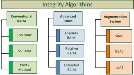
Eine intensive Literaturrecherche zeigt bereits existierende Integritätsalgorithmen auf. Es wird ein Vorschlag dahingehend gemacht, diese hinsichtlich geeigneter Kriterien zu klassifizieren. Die Algorithmen werden im Wesentlichen in drei Kategorien eingeteilt, die sich hauptsächlich in der Allokation der Verantwortung für die Integritätsaussage unterscheiden: bei vollständig autonomen Integritätsalgorithmen liegt die Bürde ausschließ- lich auf Nutzerseite, wohingegen bei den sogenannten Advanced RAIM-Algorithmen die Bürde zwischen Nutzer und System aufgeteilt wird. Beispielsweise Satelliten-basierte Augmentierungssysteme (SBAS) allokieren die Integritätsbürde fast ausschließlich auf Systemseite. Das Tragen der Bürde für die Integrität geht, entsprechend mit den jeweiligen Anforderungen, in der Regel mit einer erhöhten Komplexität für die Auswertestrategien und die Ausrüstung einher.
Im Rahmen dieser Arbeit wurde ein neuer RAIM-Algorithmus entwickelt, der auf die Rahmenbedingungen eines maritimen Nutzers eingeht. Es wird im Wesentlichen die Tatsache ausgenutzt, dass die Höhenkomponente sich kurzfristig nur marginal ändert und demnach eine geeignete Höhenreferenz darstellt. Zudem wird hier die Tatsache ausgenutzt, dass die Meeresoberfläche zum großen Teil mit dem Geoid zusammenfällt, womit eine zusätzliche und GNSS-unabhängige Höhenschätzung eingeführt werden kann. Dies erlaubt bis zu einem gewissen Grad die Überprüfung der Konsistenz mit den GNSS-Beobachtungen. Dieser neue Ansatz stellt eine Erweiterung des konventionellen Least-Squares Residual (LSR) RAIM dahingehend dar, als dass das finale Ergebnis sich aus dem Optimum beider beteiligten Ansätze definiert. Somit ist per Definition eine Verbesserung der Leistungsfä- higkeit zu erwarten, die in den entsprechenden Auswertungen bestätigt werden kann.
Ein zentraler Aspekt dieser Arbeit ist die Evaluierung der Leistungsfähigkeit der ausgewählten Ansätze hinsicht- lich Genauigkeit, Integrität und Kontinuität auf Nutzerseite. Ein entscheidender Parameter ist hierbei die Verfüg- barkeit der Integrität und Kontinuität über alle Nutzerpositionen über den gesamten Auswertezeitraum. Dabei werden drei Szenarien unter Berücksichtigung der Navigationssysteme GPS, Galileo und GLONASS definiert.
Hierbei werden im Wesentlichen drei ausgesuchte Algorithmen betrachtet: den LSR RAIM-Ansatz, der als klassi- scher RAIM-Ansatz häufig in der Literatur auftaucht. Der Novel RAIM-Ansatz stellt – wie oben beschrieben – eine Erweiterung des LSR RAIM dar. Als Vertreter der Advanced RAIM-Algorithmen ist der „Multiple Hypothesis Solution Separation“ (MHSS) RAIM zu nennen. Diese ausgesuchten Algorithmen werden detailliert beschrieben und diskutiert.
Als Ergebnis der Evaluierung der Leistungsfähigkeit der oben genannten Ansätze zeigt sich unter Berücksichti- gung einer Konstellation (GPS) eine Nicht-Konformität gegenüber den Verfügbarkeitsanforderungen. Dies ist im
Kurzfassung 5
Wesentlichen mit der Geometrieabhängigkeit gegenüber den RAIM-Algorithmen zu erklären, da anzunehmen ist, dass die jeweils schlechteste Geometrie einen Treiber für die Leistungsfähigkeit darstellt. Unter der Annahme von zwei (GPS und Galileo) Konstellationen ist zu beobachten, dass alle drei untersuchten Ansätze konform mit den Anforderungen sind, mit der Ausnahme der Kontinuität über die Dauer von 3 Stunden bei dem LSR- und Novel RAIM Ansatz.
Hingegen zeigt sich bei drei Konstellationen (GPS, Galileo und GLONASS) eine Limitation des LSR und Novel RAIM. Beide Ansätze basieren auf der Ein-Fehler-Annahme, die bei der hohen Anzahl von verfügbaren Satelliten nicht mehr gültig ist, da die Wahrscheinlichkeit von mehreren simultan ausfallenden Satelliten nicht mehr vernachlässigbar ist. Aus diesem Grund kann unter diesen Rahmenbedingungen keine sinnvolle Aussage über deren Leistungsfähigkeit gemacht werden. Generell zeigt sich, dass der MHSS RAIM den anderen RAIM-Ansätzen hinsichtlich Leistungsfähigkeit überlegen ist und volle Konformität gegenüber den Anforderungen unter Ver- wendung von mindestens zwei Konstellationen aufzeigt.
Über die Evaluierung der Leistungsfähigkeit der ausgewählten Algorithmen hinaus wird verstärkt auf das Ad- vanced RAIM-Konzept eingegangen, das die Verwendung des MHSS RAIM vorsieht. Dieses Konzept nutzt ein zusätzliches und unabhängiges Referenz-Netzwerk, das die Aufgabe hat den Nutzer mit entsprechenden Infor- mation zu versorgen, so dass dieser mithilfe dieser Daten in der Lage ist, eine geeignete Aussage über die Integri- tät seiner Positionslösung treffen zu können. Die Entwicklungen für das Konzept, das primär für den Luftfahrtbe- reich Anwendung finden soll, stehen noch in der Anfangsphase. Diese Aussage stützt sich auf der Tatsache, dass entsprechende Beschreibungen und Überlegungen ausschließlich die Rahmenbedingungen, wie sie in der Luft- fahrt vorkommen, geltend machen. Es werden in dieser Arbeit diverse Aspekte dieses Konzepts angesprochen und hinsichtlich der Verwendbarkeit für den maritimen Nutzer diskutiert. Empfehlungen werden ausgespro- chen, die in aktuelle Entwicklungen Eingang finden sollen.
Sogenannte „Overbounding“-Konzepte werden vorgestellt: ein „Overbound“ ist eine konservative Repräsentation einer zugrunde liegenden Fehlerverteilung, die - unter anderem aufgrund eines reduzierten Stichprobenumfangs - nicht zwingend einer bekannten Charakteristik entsprechen muss. Die Notwendigkeit eines „Overbounds“
ergibt sich aus der Tatsache, dass sämtliche Integritätskonzepte auf der Annahme der Normalverteilung basie- ren. Es wird eine Übersicht über vorhandene Konzepte gegeben, auf deren Basis eine Empfehlung für den mari- timen Nutzer ausgesprochen wird.
Desweiteren werden Analysen durchgeführt, die die Toleranz in der Fehlermodellierung bezüglich den aus der Luftfahrt übertragenen Fehlermodellen aufzeigen sollen. Dabei wurde die Bedingung der Konformität gegenüber den Anforderungen zugrunde gelegt. Der Fokus liegt hierbei unter anderem auf den lokalen Fehlereinflüssen wie Mehrwege-Effekten und Signal-Interferenzen. Mehrwege-Effekte und beispielsweise nominale Signaldeformati- onen werden hier als zusätzlicher Bias auf den Beobachtungen zu den jeweiligen Satelliten modelliert. Die Biases werden in zwei unterschiedlichen Analysen jeweils auf einen Satelliten und auf allen Satellitenbeobachtungen simultan modelliert. Das Ergebnis ist eine deutlich erhöhte Toleranz des Bias auf einer Satellitenbeobachtung gegenüber dem zweiten Fall. Hierbei ist zu beachten, dass der gemeinsame Bias nicht in die Schätzung der Emp- fängeruhr eingeht, sondern von dem RAIM absolut in die Positionskomponente übertragen wird. Dem gegen-
6 Kurzfassung
überzustellen sind Fehlereinflüsse wie beispielsweise Jamming oder Signalinterferenzen, die eine Inflation der Fehlerverteilung auf den Satellitenbeobachtungen verursachen können. Die gezeigte Analyse geht davon aus, dass alle Satellitenbeobachtungen simultan davon betroffen sind. Es zeigt sich eine Toleranz im Dezimeter- Bereich, wobei anzumerken ist, dass die Verwendung von drei Konstellationen eine um etwa Faktor drei erhöhte Toleranz gegenüber der Verwendung von zwei Konstellationen ergibt.
Für die Simulationen wurde eine frei verfügbare, Matlab-basierte Plattform ausgewählt, die für globale Systeme- valuierungen hinsichtlich Genauigkeit und Integrität ausgelegt ist (MAAST). Dieses Tool wurde dahingehend erweitert, dass es die Evaluierung der Leistungsfähigkeit eines maritimen GNSS-Nutzers erlaubt. Dies beinhaltet die Anpassung des bereits implementierten MHSS RAIM-Algorithmus und die Implementierung neuer Algorith- men in diese Simulationsumgebung. Außerdem wurde dieses Tool auch adaptiert um die Durchführung auxilia- rer Analysen zu unterstützen.
7
Abstract
The use of Global Navigation Satellite Systems (GNSS) in the context of maritime applications has evolved during the recent past. Some applications are classified safety critical that claim specific demands towards a GNSS. The International Maritime Organization (IMO) has defined and published requirements for those applications. A key parameter is the integrity of a position solution. Integrity is a measure of trust that can be placed in the correct- ness of the information that the system is providing to the user. Besides, integrity includes also the ability to warn a user within a specified time interval. In this context, also continuity is a relevant parameter: continuity is the ability of a system to provide continuous conformity to the needs during an operation given that the system is available at the beginning of the operation.
The aviation user community has always been the major driver for developments in the field of GNSS integrity. In fact, for example the European Geostationary Navigation Overlay Service (EGNOS) has been certified by the International Civil Aviation Organization (ICAO) in 2011. This leads to the conclusion that the conditions are better understood compared to maritime applications - especially in terms of error modelling. But also threat scenarios are defined that need to be considered in order to account for real situations.
Comparing the requirements on the one hand specified by ICAO and on the other hand by IMO, significant differ- ences get obvious such as no demands being defined for the vertical position component and continuity is speci- fied over a much longer exposure period for maritime applications. This implies the need to review and if neces- sary adapt the algorithms and the corresponding assumptions. For integrity, a possible extension of the integrity exposure period does not result in a higher or different number of events to be considered and their probability is assumed to grow linearly with the specific interval. Instead, for continuity the number or type of events to be considered is different depending on the exposure period. The consequences on the threat modelling are dis- cussed in detail.
An extensive literature survey shows existing integrity algorithms. A way to classify the algorithms is proposed:
three main categories are identified. First, fully autonomous integrity algorithms do not require input from an external source. In contrast, so-called Advanced Receiver Autonomous Integrity Monitoring (ARAIM) implies the usage of an independent reference network that provides the user with relevant input. The other extreme cer- tainly constitute augmentation systems such as Satellite Based Augmentation Systems (SBAS) that allocate the full integrity burden on system side.
A Novel RAIM scheme has been derived in the frame of this thesis that copes with the condition of a maritime user. The fact that a maritime user moves along the sea surface which is approximated by the geoid model brings in an opportunity of using additional height information. The idea is to use the additional height information in order to perform a cross-check with the GNSS-derived height.
A major focus is on the evaluation of the performance of the integrity algorithms at user level. For this, three algorithms have been selected: the Least-Squares Residual (LSR) RAIM, the Novel RAIM scheme and the Multiple
8 Abstract
Hypothesis Solution Separation (MHSS) RAIM representing the so-called Advanced RAIM schemes. A further effort consists in highlighting the concept of Advanced RAIM that relies on an external independent reference network that is in charge of computing relevant integrity parameters on ground and sending them to the user via an Integrity Support Message (ISM). The ISM parameters contain information about current error characteriza- tion and failure probability that is used to state about its integrity. Concept drivers are discussed and supported via dedicated analyses.
9
Table of Contents
Kurzfassung ... 3
Abstract ... 7
Table of Contents ... 9
1 Introduction ... 13
2 Overview of Modern Techniques for Maritime Navigation ... 17
2.1 Hyperbolic Terrestrial Systems ... 18
2.1.1 LORAN-C ... 18
2.1.2 eLORAN ... 20
2.1.3 Omega... 21
2.1.4 Decca ... 22
2.2 Satellite Systems ... 23
2.2.1 Navstar GPS ... 24
2.2.2 Galileo ... 24
2.2.3 GLONASS ... 25
2.2.4 BeiDou ... 25
2.2.5 Usage of GNSS ... 26
2.2.6 GNSS and Inertial Navigation Systems ... 28
3 General Aspects on Integrity Algorithms ... 31
3.1 Service Performance Parameters ... 31
3.1.1 Accuracy and Pseudorange Accuracy ... 32
3.1.2 Integrity ... 33
3.1.3 Continuity ... 35
3.1.4 Availability ... 36
3.2 Fault Detection and Fault Exclusion ... 37
3.3 Calculation of the k-factor ... 37
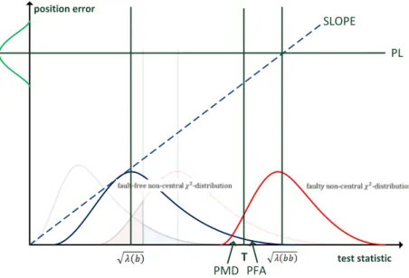
3.4 Unified Approach for Protection Level Computation ... 39
3.5 Analogy to Geodetic Network Analysis ... 41
4 Understanding of Performance Requirements ... 43
4.1 IMO ... 43
4.2 ICAO ... 47
4.3 Conclusion ... 50
10 Table of Contents
5 Integrity Algorithms ... 53
5.1 Survey of Integrity Algorithms... 53
5.2 Selected Algorithms ... 56
5.3 Least Squares Residuals RAIM ... 57
5.3.1 Test Statistics ... 58
5.3.2 Threshold Determination ... 59
5.3.3 Detectable Bias in Test Statistic... 61
5.3.4 Mapping function derivation ... 63
5.3.5 Protection Level Calculation ... 64
5.3.6 Extension to Account for Nominal Range Biases ... 67
5.3.7 Conclusion ... 73
5.4 Novel Maritime RAIM ... 73
5.4.1 Background ... 74
5.4.2 Fault Detection ... 76
5.4.3 HPL Computation ... 79
5.4.4 Conclusion ... 82
5.5 Multiple Hypothesis Solution Separation RAIM ... 82
5.5.1 Solution Separation ... 82
5.5.2 Overview ... 83
5.5.3 Computation of Subset Solutions ... 85
5.5.4 Fault Detection ... 87
5.5.5 HPL Computation ... 88
5.6 Conclusion ... 89
6 Fault-free Error Model... 91
6.1 Satellite Clock and Ephemeris Error ... 92
6.2 Ionospheric Error ... 93
6.3 Tropospheric Error ... 93
6.4 Frequency Dependent Contributions ... 94
6.4.1 Iono-Free Combination ... 94
6.4.2 Carrier Smoothed Code ... 95
6.4.3 Multipath ... 96
6.4.4 Antenna Calibration ... 98
6.5 Receiver Noise ... 98
6.6 UERE Budget ... 99
6.7 Nominal Biases ... 100
7 Threat Space ... 103
7.1 Integrity Triad ... 104
7.2 Feared Events ... 105
Table of Contents 11
7.3 Satellite Failure Probabilities ... 106
7.4 Wide Failure Probabilities ... 109
7.5 Revision of Integrity and Continuity ... 109
7.5.1 Integrity ... 111
7.5.2 Continuity ... 113
7.6 Conclusion ... 122
8 Performance Results ... 125
8.1 Position Accuracy ... 126
8.2 Integrity Performance Results ... 132
8.2.1 LSR RAIM ... 132
8.2.2 Novel RAIM ... 133
8.2.3 MHSS RAIM ... 134
8.3 Continuity Performance Results ... 136
8.3.1 LSR RAIM ... 136
8.3.2 Novel RAIM ... 137
8.3.3 MHSS RAIM ... 139
8.4 Elevation Dependency of Novel RAIM ... 140
8.5 Conclusion ... 141
9 Advanced RAIM Related Considerations ... 145
9.1 Architecture and Design Drivers ... 145
9.1.1 Overview of Segments ... 145
9.1.2 Architectural Characteristics ... 147
9.1.3 ISM Parameters ... 148
9.1.4 Conclusion ... 149
9.2 Overbounding Concepts ... 150
9.2.1 Overview ... 150
9.2.2 Impact of Reduced Number of Samples ... 157
9.2.3 Conclusion ... 159
9.3 Sensitivity Analyses ... 160
9.3.1 Multipath ... 160
9.3.2 Interference ... 166
9.3.3 ISM Latency ... 167
9.4 Conclusion ... 171
10 Summary and Outlook ... 173
Bibliography ... 175
Acronyms... 185
12 Table of Contents
Annex ... 187
A.1 MAAST ... 187
A.2 Simulation Parameters ... 189
A.3 Algorithm Key Parameter Values ... 190
A.3.1 LSR RAIM ... 191
A.3.2 Novel Maritime RAIM ... 192
A.3.3 MHSS RAIM ... 194
Acknowledgements ... 195
13
1 Introduction
In the last decades satellite based navigation became one of the most essential infrastructures of the daily life which evolved out of a GPS-based niche technology for military and professional users to a multi-provider tech- nology for a wide variety of users. Nowadays, a plethora of applications make use and rely on Global Navigation Satellite Systems (GNSS) which has therefore become an indispensable technology for navigation, positioning and timing. Moreover, GNSS is used for safety critical applications – in particular the aviation community strong- ly depends on GNSS in various life critical phases such as landing approaches where a non-sight landing of an aeroplane shall be possible in an extreme case. It is obvious that such applications require a high level of trust in the GNSS navigation solution that is called integrity. The International Civil Aviation Organization (ICAO) defines integrity as a measure of the trust that can be placed in the correctness of the information supplied by a naviga- tion system. Integrity includes the ability of the system to provide timely warnings to users when the system should not be used for its intended operation. Furthermore, an important aspect for safety critical applications is continuity. The continuity of a system is the ability of the total system to perform its function without interrup- tion during the intended operation. More specifically, continuity is the probability that the specified system performance will be maintained for the duration of a phase of operation, presuming that the system was availa- ble at the beginning of that phase of operation.
In the past, aviation was and still is the main driver for developments in the field of GNSS integrity and continui- ty. However, a further user group emerges more and more to a greater extent into awareness in the field of GNSS integrity and continuity. Analogously to the aviation, GNSS has become the main navigation means for maritime navigation in the recent past. Today, the maritime section is a worldwide commercial mass transport means.
Also maritime navigation is deemed safety critical and relies on GNSS. The International Maritime Organization (IMO) defined requirements for integrity and continuity. Those requirements differ significantly from those defined by the ICAO. IMO requirements have barely been considered in recent and current integrity algorithms and concept developments. These requirements constitute a massive challenge to adapting the existing integrity schemes in order to satisfy the needs of maritime users. This fact actually prepares the ground of this thesis.
The permanent enhancements in existing GNSS and the advent of new GNSS are reflected in this thesis by charac- terizing the maritime user as a GNSS multi-frequency and multi-constellation user. Even IMO requirement speci- fications act on the assumption that dual frequency observations are applied. Various schemes verifying integrity and continuity requirements are available: one major group of representatives are Receiver Autonomous Integri- ty Monitoring (RAIM). RAIM is a fully receiver autonomous approach that exploits the residuals of pseudorange measurements in order to perform a consistency check and to identify the presence of a potential faulty meas- urement. With the dual-frequency services and the large number of satellites available the Least-Squares Resid- uals (LSR) RAIM will have its renaissance. While the concept is known already quite for some time, it was mainly limited by the low accuracy of single-frequency ranging signals and the limited number of satellites of a single constellation which led to an integrity performance being far beyond the expectations of the aviation user com- munity. However, the potential of this scheme is undoubted and promising. In the context of this thesis a Novel RAIM scheme has been developed. This novel RAIM scheme is based on assumptions that are exclusively valid
14 Introduction
for maritime users. Namely the fact that a maritime user moves along the sea surface allows for deriving addi- tional height information based on the geoid that coincides mainly with the global sea surface. Current develop- ments in the field of integrity algorithms reveal a new group of algorithms called Advanced RAIM. The most promising hereof is the Multiple Hypothesis Solution Separation (MHSS) RAIM scheme which will be treated in more detail within this thesis. This concept relies on an external independent network of reference stations whose task is to estimate an Integrity Support Message (ISM) broadcast to the user. Needless to mention, this requires an additional infrastructure on top of the GNSS ground segment whose design aspects will be treated in detail within this thesis.
A key objective of this thesis is to provide an understanding of the needs of a maritime user and work out the differences in the requirements of ICAO on the one hand and IMO on the other hand and highlight the implica- tions on the designs of algorithms. Extensive performance evaluations based on different RAIM concepts are conducted in order to clearly make a statement whether current GNSS are able to satisfy the need of the mari- time user based on RAIM techniques. A major part of this thesis is dedicated to highlighting the implications to Advanced RAIM design employing MHSS RAIM. Based on extensive analyses, clear recommendations are given to support current development efforts enabling integrity and continuity also to the maritime user group. The thesis is intended to contribute to long term evolutions of integrity concepts by evaluating promising algorithms and to identify and refine potential system architecture, to deeply assess the performance and the drivers of the different algorithms and to identify a clear way forward in terms of investigation and realization steps.
Outline of the Thesis
Chapter 2 - Overview of Modern Techniques for Maritime Navigation
Before the advent of aviation, maritime applications in general were one of the main trigger for developments in the field of navigation. However, to give a full overview of maritime navigation means is not the intention of this chapter, rather to provide a meaningful overview over the main navigation techniques that have been used and/or are still in use since the middle of the 20th century. Although the focus in this thesis is with no doubts on GNSS solely, this chapter aims at putting GNSS as such into the context of other navigation means and thus provides a full picture in which GNSS plays a major role these days. Also, this chapter is used to provide an introduction into GNSS.
Chapter 3 – General Aspects on Integrity Algorithms
After having given an introduction to GNSS in general, this chapter aims at further pointing towards the content of this thesis by providing details on relevant aspects for integrity algorithms in particular. This comprises an understanding of the service performance parameters – namely accuracy, integrity, continuity and availability.
Their relationships together with their definitions are provided. Algorithms are designed to detect vulnerable faults with sufficient probability to ensure their integrity. Thus, some details on integrity algorithms are provid- ed regarding their capability of fault detection and fault exclusion. Finally, in order to provide a solid understand- ing of an integrity algorithm, a unified approach for protection level computation is depicted. It will be shown later on in this thesis that other algorithms can be related to the logic presented in this last subsection.
Introduction 15
Chapter 4 – Understanding of Performance Requirements
After having provided a basic understanding of RAIM algorithms, their design and functionalities, this chapter aims at summarizing the minimum required performance level. Hereby, the different sets of requirements – on the one hand from the aeronautics and on the other hand from the maritime users – are worked out. The Interna- tional Civil Aviation Organisation (ICAO) defines the needs for the aeronautics whereas the International Mari- time Organization (IMO) defines those for the maritime user.
It is important to understand that the design parameters in every RAIM algorithm are derived from the applica- ble set of requirements for each GNSS operation respectively. The different sets are compared and discussed in detail. The main goal of this chapter is to present the baseline set of requirements that will be used throughout this thesis.
Chapter 5 – Integrity Algorithms
At this point, the basis for an understanding of integrity algorithms is provided. This chapter gives an overview of existing algorithms and proposes a classification of these algorithms into three main groups: the first group comprises the fully autonomous integrity algorithms, also known as RAIM. The second group is formed by the so-called Advanced RAIM techniques. The third main group covers the augmentation systems in general such as SBAS and GBAS. Their characteristics and relationship to each other is described in detail in this chapter.
From the set of these algorithms, three candidates have been selected to be further studied within this thesis.
The algorithms together with their characteristics, advantages and disadvantages are presented and discussed in detail within this chapter.
Chapter 6 – Fault-Free Error Model
In order to assess the performance of an integrity algorithm by simulation, the conditions in which the algorithm is conducted have to be defined. Hereby, the fault-free error models define the assumed nominal performance level of a GNSS. It has to be distinguished between error contributions which are under control of the GNSS itself such as ephemeris and clock error and error contributions such as atmospheric and local errors (i.e. multipath) that depend on the user environment. The fault-free error model gives conservative assumptions about the error characteristics. These are empirical error models derived from long-term measurement campaigns. The respec- tive error distributions are conservatively overbounded in a sense that the real underlying performance level can be assured.
Chapter 7 – Threat Space
The threat space is a consistent set of assumptions under which the integrity and continuity performance is assessed. It defines basically the satellite failure probabilities and the probability of a constellation to fail. Anoth- er major aspect of this chapter is the discussion for the need of a maritime dedicated threat space. In contrast to the aeronautics being the main driver for standardization and development activities, the maritime user lacks of a maritime dedicated threat space. This point is discussed extensively. In addition, this investigation bears some novel aspects to be considered in a maritime dedicated threat space.
16 Introduction
Chapter 8 – Performance Results
This chapter summarizes the performance evaluation results related to the set of selected algorithms. The re- sults are derived via simulation and depicted with respect to accuracy, integrity, continuity and availability. For the performance evaluation, three different scenarios have been assumed: single, dual and triple GNSS constella- tion. The intention is to also cover near future developments where multiple constellations will be available for usage. All performance results will be summarized and discussed in this chapter.
Chapter 9 – Advanced RAIM Related Considerations
As will turn out from the latter chapter, the MHSS RAIM as representative of Advanced RAIM shows the most promising results in terms of performance. This chapter shall focus exclusively on aspects relevant for Advanced RAIM and works out the implications on its architecture and design if amended for maritime GNSS users. In general, the main drivers of the Advanced RAIM concept are worked out and discussed taking into account maritime user requirements.
Chapter 10 – Conclusion and Outlook
Finally, an extensive discussion on the findings and final conclusions is provided. This chapter shall also summa- rize recommendations for future developments in the frame of maritime integrity. In addition, an outlook on potential further investigations and a proposed way forward is depicted.
17
2 Overview of Modern Techniques for Maritime Navigation
Maritime navigation is a broad field with a long history. In the beginning, navigation was mostly based on astro- nomical observations by looking to constant objects like the sun, the moon and the stars and using them to estimate a position. For example the sextant was becoming one of the main navigation tools in the 18th century allowing for positioning with accuracy much better than ever before.
A selection of various techniques that arose during the last century and those with the biggest impact on ship navigation will be introduced. With the advent of GPS and further GNSS, satellite navigation became more and more the most commonly used aid. But before satellite navigation was available, so-called hyperbolic terrestrial systems constituted the status quo.
Enhanced LORAN (eLORAN) is about to attain new attention in the near future as the descendant of LORAN-C which was a ground-based navigation system operated by the U.S. Coast Guard. In May 2009, the system was declared obsolete and plans have been announced to terminate it [GPS 2016]. The Coast Guard began shutting it down in February 2010. A strong lobby pushes currently for reanimation of the system under the acronym eLORAN. According to the “Enhanced Loran Definition Document” [International Loran Association 2007], the LORAN-C infrastructure is planned to be retained and upgraded to become eLORAN. The main motivation for this development is the fact that eLORAN perfectly suits as backup solution for GNSS that is vulnerable to jam- ming and spoofing. Actually, eLORAN is more robust to those kinds of threats and hence might serve as a com- plementary navigation means [Divis 2015].
For complementary reasons also the OMEGA and Decca system are marked out. Omega has been developed in the 1960s in the USA and is fully deployed in 1982. As opposed to LORAN-C (or eLORAN) and Decca, OMEGA has global coverage. The fact that the system operates on very low frequencies increases the complexity at the user receiver level. A typical accuracy is in the order of 1 NM. Omega has been taken out of service in 1997 [Kayton et al 1997]. Decca was also a hyperbolic based navigation system that has been originally developed during World War II for maritime navigation purposes. The system was shut down in the year 2000.
Nowadays and in the future, satellite systems play a key role in maritime navigation. The major GNSS are intro- duced in this chapter. Additionally, the integration and combination of GNSS with other navigation aids such as inertial sensors is shortly introduced to provide the full overview.
The aim of this chapter is to provide an overview of maritime navigation and to identify the role of GNSS as a component in modern maritime navigation that becomes more and more important in the future. In order to put GNSS in a maritime context where also other navigation techniques are commonly in use an overview of those systems is provided in this chapter.
18 Overview of Modern Techniques for Maritime Navigation
2.1 Hyperbolic Terrestrial Systems
Hyperbolic terrestrial navigation is based on the difference in timing between the receptions of signals from two stations on ground. The basic idea behind is the intersection of the hyperbolic lines resulting from the measured delays between the user’s position and the reference stations. The first hyperbolic navigation systems have been developed during the beginning of the 20th century. Since then, different systems have been developed and established.
2.1.1 LORAN-C
The principle of Long Range Navigation (LORAN) navigation is based on curve cutting using distance differences between the user and several static stations. The LORAN signal is emitted using the 100 kHz frequency band that can be received up to 1000 kilometres away from the emitting station [Forssell 2008], [Weblink 2014d]. The version of LORAN-C is based on a network of stations that are distributed with a distance of several 100 kilome- tres. Figure 2-1 shows the global distribution of LORAN-C stations. LORAN-C covers wide areas such as the North Pacific, North Atlantic, the Mediterranean, North- and Eastern Sea, the Red Sea and the Persian Gulf [Weblink 2014d].
Figure 2-1: Global Distribution of LORAN Stations [Weblink 2014d]
Each LORAN-C system realization comprises transmitters, control stations and System Area Monitors (SAM).
LORAN stations are grouped together into chains and basic navigation relies on using a specific chain. In each chain, there is a master station and several secondary stations.
Hyperbolic Terrestrial Systems 19
Master Station X Station Y Station Z Master Station X
Group Repetition Interval for Chain 9940 CHAIN 9940
Time Note: Each hash represents a pulse
Figure 2-2: LORAN Chain Signals [Sherman 2003]
In LORAN-C, each station transmits a group of eight pulses (nine for the master station) at a specified interval.
The amount of time between transmissions of the pulse groups, known as the group repetition interval (GRI), is unique to each chain. Hence chains are designated by their GRI. Some stations transmit signals for two different chains. These are termed dual rated stations [Forssell 2008], [Sherman 2003]. The GRI is usually expressed as a multiple of ten microseconds, i.e. GRI 7960 = 79600 microseconds. Figure 2-2 illustrates the 9940 chain trans- missions. Each hash mark represents one LORAN pulse (which is 250 microseconds in length). The pulse has a specified shape or envelope that aids in tracking the correct cycle. Typically the tracking point is set around 30 microseconds (or the sixth zero crossing) after the start of the pulse. As the signal propagates, the envelope may shift relative to the underlying carrier (and hence the tracking point). This shift is termed the envelope to cycle difference (ECD).
The power of LORAN transmissions allows users at distances of 800 km or more to receive these signals. The transmitters emit a set of LORAN pulses at precise time instances. Within a chain, the transmission time of each secondary station is specified as an offset from the transmission of the master station. The SAMs regulate the transmission offset. Traditionally, position determination is based on measuring the distance difference of arrival (TDOA) of pulses from the master and a secondary station in a chain to create lines of position (LOPs). A minimum of two LOPs are required to determine a position. Newer technology has resulted in LORAN receivers capable of operating without requiring a master station signal. They also can determine positions using signals from stations in different chains (all stations in view) to improve the LORAN performance. These receivers are known as “all-in-view” (AIV) receivers. Processing permits the calculation of a range measurement using the signal time of arrival (TOA) provided that the receiver has rough knowledge of the current time and station identification. Using TOA is akin to using GNSS pseudoranges [Forssell 2008], [Sherman 2003].
There are two ways of LORAN signal propagation. The signals propagate as a groundwave along the Earth's surface. They also propagate as a skywave by reflecting from the ionosphere. TDOAs are calculated using the groundwaves since they are more reliable and their phase is more stable. Skywave reflections can interfere with the desired groundwave signals much like multipath in GNSS. Typical skywaves arrive as early as 32-35 micro- seconds and as late as 1000 microseconds after the reception of the groundwave [Forssell 2008]. The ground-
20 Overview of Modern Techniques for Maritime Navigation
wave from a station can interfere with the groundwave of another station if they are not in the same chain. This type of interference is called cross rate interference since it is due to stations transmitting at different rates.
The propagation speed of the LORAN groundwave is dependent on factors such as ground conductivity. These properties change the signal propagation speed from the speed of light in vacuum. For navigation only the groundwave part is used. The primary (PF), secondary (SF) and additional secondary factors (ASF) influence the groundwave velocity from the transmitter to the user. The first term is the propagation speed in space. On top of that, the signal experiences some extra delay if it travels over a seawater path, called the secondary factor. Final- ly, signals traveling over a land path will experience an additional delay over an all seawater path, called ASF.
These three factors are only effective at the part of the total trajectory where the propagation mechanism has a far-field character. PF is solely dependent on distance while ASF need to be measured or modelled. On its trip to the receiver, a blend of interferences adds to the LORAN-C signal. This blend consists of continuous wave inter- ference, interference from other LORAN-C stations and atmospheric noise. When the signals arrive at the receiv- er antenna, locally generated noise from engines or receiver electronics will further dilute the LORAN-C signal.
Depending on the application and the local signal conditions, either an electric-field or a magnetic-field type antenna may actually receive the electromagnetic signal [Forssell 2008].
2.1.2 eLORAN
LORAN systems are designated to a series of radio based navigation systems that are used for positioning and navigation. Among this series, eLORAN is the latest in the longstanding and proven series of LORAN systems but still about to being deployed. LORAN-A is the first LORAN system and developed during World War II, initiated by the US Navy. LORAN-C is the further development of the previous versions LORAN-A and LORAN-B which is described in a dedicated section.
It needs to be pointed out that the following description of the eLORAN system is based on the Enhanced LORAN Definition Document [International Loran Association 2007] which does not fully define the system but is a first out of several documents. It is planned to tighten requirements in the system design in order to serve new appli- cations. The basis of the eLORAN signal is the LORAN-C signal and the possibility of the continuation of using existing LORAN-C receivers is foreseen. However, in that case the benefits of eLORAN are excluded [International Loran Association 2007].
Figure 2-3 highlights a rough sketch of the eLORAN system concept that comprises of transmitting stations and monitor sites connected to a control centre. The measured propagation delays at the monitor sites are used to compute corrections at the control centre for the user. The major improvement compared to LORAN-C is the usage of an additional data channel to provide differential corrections to the user. This additional feature allows eLORAN to reach a new level of perfomance and thus the possibility to serve applications with more stringent demands. For further details, it is referred to [International Loran Association 2007].
Hyperbolic Terrestrial Systems 21
Figure 2-3: eLORAN System Concept [International Loran Association 2007]
2.1.3 Omega
The Omega navigation system is a long-range radio system developed by the U.S. Navy and no more available since 1997 [Kayton et al 1997]. It provides full-time worldwide coverage from eight strategically located terres- trial very-low frequency transmitting stations. Omega is a hyperbolic navigation system using phase comparison of very-low frequency (10 to 14 KHz) continuous-wave radio signals and can be used by aircraft, ships, land vehicles and also by submarine at moderate antenna depth of about 12 to 15 meters [Forssell 2008], [Van Etten 1976].
Table 2-1: Omega transmitter stations [Forssell 2008]
Station Location Transmitter Antenna Administered by A Bratland, Norway Suspended wires across a
fjord Norwegian Tele-
communications Administrations B Monrovia, Liberia Grounded tower with radial
top elements Ministry of Industry and Commerce
C Haiku, Hawaii As A US Coast Guard
D La Moure, North Dakota Bottom-isolated monopole As C E Reunion in the Indian
Ocean (France) As B French Navy
F Golfo Nuevo, Argentina As D Argentine Navy
G Woodside, Victoria,
Australia As B Department of
Transport H Tsushima, Korean Strait,
Japan As D Japanese Coast Guard
22 Overview of Modern Techniques for Maritime Navigation
All Omega transmitters (see Table 2-1) are synchronized in phase and transmit on each of 3 common navigation frequencies: 10.2, 11.33, and 13.6 kHz. Synchronization is maintained by synchronized atomic clocks. Each transmitter A to H respectively has a unique frequency that is used for identification. The signal format of the system is such that each station transmits signal segments that are separated by a time interval of 0.2 seconds.
The repetition frequency of the signals is 0.1 Hz. Further information about signal format is found in [Forssell 2008].
Phase differences between signals received from a pair of transmitters determine a set of hyperbolic lines of position separated one from another by a phase difference of 2π radians, corresponding to a distance difference of one wavelength λ. On the baseline between stations, the lane width is approximately 15 km if only the 10.2 kHz transmissions are used; the lanes can be resolved to approximately 45 km by employing the difference frequency of 3.4 kHz with respect to 13.6 kHz frequency for phase measurements. Similarly, if the 11.33 kHz frequency is also used, the resolution is around 133 km. Dead-reckoning or redundant Omega phase measure- ment can be used to resolve this 133 km ambiguity. However, it became necessary to enlarge the non-ambiguity area further, and a fourth transmitter frequency, 11.05 kHz, was introduced. The difference frequency between this one and 11.33 kHz gives a lane width of about 529 km.
Transforming from Omega phase coordinates into a terrestrial reference frame (latitude and longitude) would be relatively easy if the velocity of propagation of the very-low-frequency signals was constant. Unfortunately, it is not constant but is a function of several parameters, such as time of day, season, direction of propagation, solar activity, earth conductivity, etc. First, there is a natural random fluctuation that cannot be reduced by any known method. Second, there is a systematic variation mainly due to the above factors and systematic errors will persist even after these factors have been corrected because of deficiencies in the propagation model. Estimates of Omega position accuracy vary from 0.9 to 1.5 km in the day-time, and double that value at night. Thus, Omega is a low accuracy system [Van Etten 1976]. A technique known as differential Omega may be employed to improve the accuracy of the Omega system: an Omega monitoring at a known location establishes real-time Omega phase values. The difference between a set of fixed reference values for that location and these real-time values are called differential corrections and are transmitted to mobile users in the area. The mobile user applies the same real-time differential corrections to his observed phase values. The technique is based upon the principle that phase changes at the monitor station and at the user’s receiver due to propagation are well correlated [Forssell 2008], [Van Etten 1976].
2.1.4 Decca
Decca is a low-frequency hyperbolic navigation system using continuous-wave phase comparison. This system is out of service since 2000. The transmitting stations are arranged in so-called chains consisting of a main station (master) with control functions and several slaves whose signals are phase locked to those of the main station.
The master station transmits at a frequency of 6 f (f being the fundamental frequency of about 14 kHz) and 3 slave stations transmit at frequencies of 5 f, 8 f and 9 f, respectively. These coherent frequency transmissions are received by the mobile receiver and frequency-multiplied to a common frequency. Phase measurements are then made between the master and slave signals at these comparison frequencies. Each phase-difference measure-
Satellite Systems 23
ment represents a hyperbolic line of position and 2 or more define a position fix. However, there are multiple lines of position that represent the same phase difference and, on the base line between the master and slave stations, identical phase differences are spaced at a distance c/2fc, where c is the velocity of light and fc is the comparison frequency at which the phase difference is measured. The main limitation of the Decca system is sky wave contamination of the ground wave signal. This seriously degrades phase accuracy and the lane identifica- tion may be unacceptable beyond a distance of about 400 km in the daytime and 160 km at night between transmitter and receiver [Forssell 2008], [Van Etten 1976].
The system is British and was introduced during World War II. It has been used mainly in Europe where most of the coastal waters are covered, but also in Japan, India, Pakistan, the Persian Gulf, South Africa and parts of Australia and Canada (although some of these regions are no longer covered). Consequently, it is a very wide- spread area radio navigational system, and in 1987 there were 140 stations in 42 chains in 17 countries [Beattie 1988]. In Norway there are six chains, Skagerak, Vestlandet, Trondelag, Helgeland, Lofoten and Finnmark. Decca is mainly used by ships and, to some extent, by aircraft as well, especially helicopters. Trials on land have also shown fairly good results, both in the United Kingdom [Powell 1982] and Norway [Forssell 2008]. The accuracy of the Decca system is, to a large extent, dependent on the position of the user with regard to the transmitting stations, the time of year and the time of day. Even if the distances from the receiver to the transmitters are well within the stated range of the system, the accuracy varies because of propagation condition changes. The stand- ard deviation of Decca position errors is often counted in hundredths of an average lanewidth (called a cen- tilane), this unit being defined to be 5 m [DECCA 1979]. Thus, this corresponds to position accuracy in the order of a few hundred meters to several kilometres.
2.2 Satellite Systems
With the use of artificial satellites, new approaches for navigation have become possible. First satellite based systems were based on Doppler counts. The US Marine developed the Navy Navigation Satellite System (NNSS) also known as Transit in the 1950s and 1960s as being the predecessor of the GPS [Geodesy, Trends and Pro- spects 1978]. In this context also the Russian system called Cicada which is similar to the Transit system is to be mentioned. However, those systems are not in use anymore nowadays. Present-day GNSS are based on the ranging principle and are comprised of three segments [Bauer 2003], [Forssell 2008]:
• The space segment containing the satellites in orbit that provide the ranging signals and data messages transmitted to the user equipment.
• The ground segment tracks the satellites in their positions and monitors the health and status of the sat- ellite subsystems. Furthermore, the ground segment collects pseudorange and carrier phase measure- ments at the remote monitor stations to determine almanac, ephemeris and satellite clock corrections.
• The user segment consists of the equipment to perform navigation, timing and other user related func- tions.
24 Overview of Modern Techniques for Maritime Navigation
2.2.1 Navstar GPS
In the early 1960s, several US government organizations, including Department of Defence (DoD) were interest- ed in developing a global satellite system for three-dimensional positioning meaning latitude, longitude and altitude. The requirement was to continuously operate on a global basis under all weather conditions, serving high-dynamic platform ability and high accuracy. For the past several years, 31 operational GPS satellites have been in orbit plus 3-4 decommissioned satellites that can be reactivated if needed. GPS satellites fly in Medium Earth Orbit (MEO) at an altitude of approximately 20200 km. The satellites in the GPS constellation are placed in six Earth-centred orbital planes with a minimum of four satellites in each plane. The ground segment of GPS consists of three different components: the Master control station located near Colorado Springs in US, several monitor stations and the ground antennas.
GPS signals are based on the Code Division Multiple Access (CDMA) principle to distinguish signals coming from different satellites [Parkinson et al 1996]. The legacy GPS satellites broadcast ranging code and navigation data on two carrier frequencies. These two frequencies are referred to L1 centred at 1575.42 MHz and L2 centred at 1227.60 MHz. Each GPS satellite transmits two different codes: Coarse/Acquisition (C/A) code at L1 and the encrypted Precision signal (P(Y)) at both L1 and L2. The L1 and L2 carrier signals are currently modulated by pseudorandom noise (PRN) sequences using Binary Phase Shift Keying (BPSK) modulation [Hofmann-Wellenhof et al 2001]. Since each satellite uses the same carrier frequencies, the signals are separated with a unique PRN sequence associated with each satellite.
With the upcoming of other GNSS, the GPS system is in competition. Hence the pressure on the existing system to improve performance was growing which led to efforts to modernize the GPS system. In the late 1990s, a mod- ernization program was initiated by the US government including an upgrade of the space and ground segment.
A major focus in this program is adding new navigation signals to the satellites. These new signals are designed for civilian use: L2C, L5 and L1C. A more detailed description of GPS can be found in the following references [Parkinson et al 1996], [Hofmann-Wellenhof et al 2001], [Bauer 2003], [Seeber 1989].
2.2.2 Galileo
Galileo is the European GNSS that is currently in its deployment phase towards Full Operational Capability (FOC).
The In-Orbit Validation (IOV) phase has recently been carried out successfully. The next step in the program is towards Initial Services. The FOC is expected to be achieved around 2020.
The FOC constellation consists of 30 satellites (27 operational plus 3 spares) which fly in 3 orbital planes at an inclination of 56° to the equator. The satellites are equally distributed over each plane at a height of approxi- mately 23222 km. The first two experimental navigation satellites, Galileo In-Orbit Validation Element GIOVE-A and GIOVE-B were launched in 2005 and 2008 for testing purposes. The Galileo satellites transmit navigation signals at four different frequency bands, namely E5a, E5b, E6 and E1.
The ground segment is responsible for maintaining proper operations of the system. Galileo Sensor Stations (GSS) are globally distributed to collect amongst others code and carrier phase measurements and send them to
![Figure 2-3: eLORAN System Concept [International Loran Association 2007]](https://thumb-eu.123doks.com/thumbv2/1library_info/1979821.1324/23.892.266.669.129.411/figure-eloran-system-concept-international-loran-association.webp)
![Table 4-1: Summary of operational requirements for a worldwide radionavigation system according to resolution A.1046(27) published by the IMO [IMO 2011]](https://thumb-eu.123doks.com/thumbv2/1library_info/1979821.1324/47.892.146.789.182.357/summary-operational-requirements-worldwide-radionavigation-according-resolution-published.webp)