15
thInternational Conference on Greenhouse Gas Control Technologies, GHGT-15 15
th- 18
thMarch 2021 Abu Dhabi, UAE
Assuring integrity of CO
2storage sites through ground surface monitoring (SENSE)
Bahman Bohloli
a*, Luke Bateson
b, Christian Berndt
c, Tore I. Bjørnarå
a, Ola Eiken
d, Audrey Estublier
e, Regula Frauenfelder
a, Jens Karstens
c, Roberto Martínez Orio
f, Timothy Meckel
g, Nazmul H. Mondol
h, Joonsang Park
a, Amirali Soroush
i, Antoine Soulat
e, Per M. Sparrevik
a, Ceri Vincent
b, Malte Vöge
a, Ivar-Kristian Waarum
a, Joshua White
j, Ziqiu Xue
k, Zoya Zarifi
l, Iñaki Álvarez Gutiérrez
m, Juan Andrés Marín Vidal
maNorwegian Geotechnical Institute, Sognsveien 72, 0855 Oslo, Norway, bBritish Geological Survey Keyworth, NG12 5GG, United Kingdom,
cGEOMAR Helmholtz Centre for Ocean Research Kiel, Wischhofstr. 1-3, 24148 Kiel, Germany, dQUAD GEOMETRICS NORWAY AS, Kjøpmannsgata 5, 7013 Trondheim, Norway, eIFP Energies nouvelles, 1 & 4 avenue de Bois-Préau 92852 RUEIL-MALMAISON, FRANCE,
fSpanish Geological Survey (IGME), Rios Rosas 23, 28003, Madrid, Spain, gThe University of Texas at Austin, 301 E. Dean Keeton St. Stop C1, 78712-1068, Austin, Texas, USA, hUniversity of Oslo, Department of Geosciences, Sem Sælands vei 1, 0371 Oslo, Norway, iCSIRO Energy -
Commonwealth Scientific and Industrial Research Organisation, Clayton VIC 3168, Australia, jLawrence Livermore National Laboratory, Livermore, CA 94551, USA, kResearch Institute of Innovative Technology for the Earth (RITE), Kizugawadi 9-2 Kizugawa-shi, 619-0292, Kyoto,
Japan, lEQUINOR ENERGY AS, Postboks 8500 Forus, 4035, STAVANGER, Norway, mFundación Ciudad de la Energía (CIUDEN), AVDA Presidente PODRiguez Zapatero S/N, 24492, Cubillos Del Sil, Spain.
Abstract
Monitoring of geological CO2 storage is crucial for large-scale injection to gain public acceptance. Monitoring plans for large-scale operations need to include both the injection and post-injection phases to assure CO2 is safely stored permanently. The SENSE project aims to develop reliable, continuous, and cost-efficient monitoring based on ground movement detection combined with geomechanical modeling and inversion, utilizing new technology developments, data processing optimization, and interpretation algorithms. The proposed research activities include:
• demonstration of continuous monitoring of surface deformation and subsurface pressure distribution using satellite data, water pressure sensors and fiber optics;
• quantitative characterization of critical geomechanical and hydraulic parameters and automatization routine for data processing and interpretation;
• optimization of sampling arrays in order to offer storage site operators a cost-effective monitoring option as part of an effective site assurance program.
The SENSE project brings together experts from 14 international institutions of nine different countries to solve challenges in CO2 storage site monitoring and to provide solutions for safe and successful injection and post-closure phases of site operation. The project is organized in five Work Packages (WPs); WP1: Quantification of ground movement, WP2: Geomechanical modeling and rock strain assessment, WP3: History matching inversion and coupled flow-mechanics, WP4: Integration of results for cost-effective monitoring and WP5: Project management.
* Corresponding author. E-mail address: bahman.bohloli@ngi.no
The ultimate goal of SENSE is to offer storage site operators a cost-effective monitoring option that can form part of an effective site assurance/monitoring program and feed into workflows for an early alert system to detect unexpected changes in the subsurface.
The SENSE project has four demonstration sites for monitoring technologies and developing concepts and procedures. These sites are both onshore and offshore. The onshore sites include In Salah (Algeria) and Hotfield Moors (UK). For these sites, the project will use satellite data to explore the response of the surface to pressure changes in the subsurface. Algorithms for automatic satellite data processing to facilitate quick access to ground elevation data for site operators are under development at the British Geological Survey (BGS) and Norwegian Geotechnical Institute (NGI). The offshore sites include Bay of Mecklenburg (Germany) and the Gulf of Mexico (USA). In addition, the SENSE partners have requested access to data from the Troll Gas Field, the North Sea, to study its subsidence due to production-related pressure reduction. The Troll Gas Field is located next to the storage site considered for the Norwegian Long Ship project, and its data will provide a good understanding of the geomechanics of the area.
In this paper, we present the work on the In Salah and the Bay of Mecklenburg sites. New InSAR data from the In Salah are used to evaluate the ground movement during the post-injection period and thus to assess the behaviour of the storage site after completion of the injection phase. Bay of Mecklenburg is an offshore site for field experiment to inject a gas underground, build-up pressure, uplift the seafloor and measure the resulted uplift. The first field campaign at the Bay of Mecklenburg was completed in late 2019. It provided both gravity cores from the seabed and geophysical data acquisition for characterizing the shallow subsurface layers. The gravity cores were characterized for physical and mechanical properties. The material properties were used for simulating injection and response of the seafloor to induced pressure. Geomechanical 2D and 3D simulations show that the reservoir may sustain very low overpressure before it fails. Hence, this magnitude of overpressure may create a seafloor uplift of about a few millimeters to a couple of centimeters. The monitoring techniques are therefore being designed to capture uplift in this order of magnitude during the injection operation.
Keywords: CO2 storage monitoring; Fiber optics; Geomechanics; InSAR; Offshore monitoring; Seafloor deformation; SENSE-ACT; Uplift.
1. Introduction
For Carbon dioxide Capture and Storage (CCS) to have a significant impact on climate targets, large quantities of CO2, on the order of Giga-tons per year, need to be captured and stored. Monitoring of geological CO2 storage sites is crucial for gaining acceptance of CO2 storage as a reliable method for reducing CO2 emissions as well as for verification of site behavior and to enable storage site closure in the long term. Monitoring plans for such large-scale storage sites need to include both the injection and post-injection phases to assure CO2 is stored over geological timescales and effectively monitored in the subsurface. A bottleneck for the deployment of CCS, although not insurmountable, is the economics of operation including the high cost for storage site monitoring. The ambitious goal of SENSE is to demonstrate how ground surface movement can be used as an integral part of the monitoring program to verify safe storage of CO2 underground effectively.
Injection of fluids into the subsurface or production of hydrocarbon or water is known to cause dilation/compaction of the reservoir rock which propagates upwards causing uplift/subsidence at the surface. The pattern of deformation and any anomalies give an indication of the distribution of injected fluid. In terms of CCS, advanced interpretation (via inversion) of uplift data coupled with other data sources provides quantitative information on the process such as the location of the pressure front, which can be used to infer the location of the CO2 plume and any pressure barriers in the subsurface.
SAR interferometry has been identified as a potential technique to monitor (onshore) CO2 injection operations.
Eide [1] reviewed several remote sensing techniques to suit carbon capture and storage monitoring. Among the studied remote sensing technologies terrain motion monitoring by InSAR, direct and indirect use of hyperspectral
storage site to map pressure changes at depth. Morris et al. [3] used InSAR data within the In Salah project to determine injection-induced mechanical deformation. The authors compared the deformations measured by InSAR with simulated uplift, including conducting and bounding faults to achieve agreement. Further, White et al. [4]
investigated the geomechanical behaviour of the reservoir and the caprock, by combining InSAR-base deformation measurements with several ground-based measurements, including well logs, leak-off and formation integrity tests, core measurements, 3D and time-lapse seismic, water quality monitoring of the shallow aquifer, and surface gas monitoring. Ground surface monitoring at In Salah CO2 storage site showed that injection of CO2 into a 20 m thick sandstone reservoir at a depth of 1800 m below surface caused an uplift of about 20 mm at the surface. Furthermore, the signature of subsurface structures such as fractures and faults and the in-situ stress fields were observed on the uplift images constructed from InSAR [4-8].
Fig. 1. Overview of SENSE project. (a) to (d) are after [9-12], respectively.
The links between the ground uplift and pressure changes in the reservoir and overburden, and the impact of mechanical parameters of the subsurface layers is not well constrained. More studies and demonstrations are needed to explore the role of geological material and the effect of imposed changes in the subsurface on ground uplift or subsidence to build confidence in procedures and concepts. Further studies are also necessary to build confidence in geomechanical models being suitable to determine ground movement and for gaining information about pressure changes subsurface. Therefore, the SENSE research activities are focused on injection demonstration sites. The main findings will offer storage site operators a cost-effective monitoring option that can form part of an effective site assurance/monitoring program and feed into workflows to set up an early alert system for unexpected subsurface changes.
2. InSAR analyses for the In Salah site
Recent SAR satellites provide data that enable the measurement of surface displacement with high temporal and spatial resolution over large areas. ESA's Sentinel-1 constellation (comprising two satellites, the first launched in 2014, the second in 2016) offers a high temporal resolution, with a revisit time of 6 days for the European continent, and up to 12 days in equatorial regions, with a spatial resolution of about 5×20 m. This is generally good enough to capture the uplift patterns expected from large scale CO2 injection sites. Being designed for global monitoring, continuous InSAR image stacks are available from early 2015 for almost all landmasses worldwide. Sentinel-1 data are available free-of-charge. Its regular data acquisition enables us to test near-real time radar data processing strategies to continuously monitor injection sites.
(a) (b)
(c) (d)
Fig. 2. Case studies in SENSE project. (a) In Salah, from [Google Maps], (b) Hatfield Moors, UK, [Google Earth], (c) Bay of Mecklenburg, Germany, (d) location of the High Island field and CO2 capacity estimates for the coastal region of Texas [13].
New InSAR data over Krechba field, In Salah, have been acquired for the post injection time. The following datasets were provided to SENSE project by the In Salah Gas JV through TRE Altamira:
• EnviSat, 2003–2010
• Radarsat-2, 2008–2016
• TerraSAR-X, 2010–2016
In addition, we have acquired and processed such data for the time period of 2016 - 2020 in order to extend the coverage of the data over whole post injection up to 2020. These data were from Sentinel-1 satellite and have a spatial resolution of 15×15 m. The InSAR data from the injection period have been mainly presented for points and cross sections of the uplifted area, as shown in Fig. 3(a). The map in Fig. 3(b) shows the whole uplifted area around three injectors at In Salah. This is an ongoing work to calculate the uplifted area's volume and infer the total rock deformation in the reservoir through geomechanical modeling. Using the whole dataset from 2003-2020, we will also demonstrate how surface deformation changes during and after injection.
3. Bay of Mecklenburg 3.1. Description of the site
Bay of Mecklenburg is situated in the Baltic Sea with a maximum water depth of 28m. It is bounded by the Fehmarn belt in north west, Denmark in north, the shallow threshold Darss Sill in east and Germany's shore in south [14].
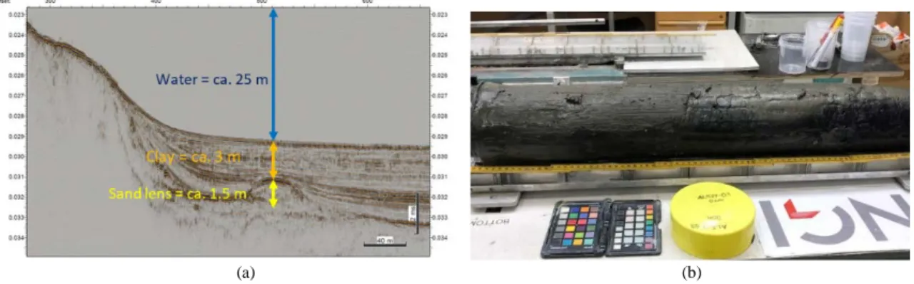
(a) (b)
Fig. 4. (a) cross section of the sediment at Bay of Mecklenburg; (b) a picture of core from gravity core GC03.
The Baltic Sea Basin and its sub-basins including Bay of Mecklenburg was formed during Pleistocene by glaciers [15]. After deglaciation, the Baltic Ice Lake started to develop at ca. 13 ka BP. The Baltic Ice Lake stage ended at the Younger Dryas-Preboreal boundary at 10.3 thousand years (ka) BP. A transgression led to the Yoldia Sea (10.3- 9.5 ka BP), containing brackish water. The connection to the ocean closed because of the glacio-isostatic uplift and created the Ancylus lake around 9,5 ka BP. The lake rose to sea-level around 9 ka BP [16] connecting it with the North Sea. This evolution led to situation in which impermeable muddy sediments overlie sandy deposits from the ice ages causing a distinct permeability inversion at shallow depth below seafloor. This is ideal for a scaled-down injection test that can serve as a rapid response analogue for large-scale industrial injection of CO2.
3.2. Physical and mechanical testing of sediment cores
Physical and mechanical testing of sediment cores from the Bay of Mecklenburg were carried out and the results are shown in Tables 1 and 2. Grain size analysis of the clay/silt and sand samples were carried out based on the laser diffraction method using Beckman Coulter LS13320. The method is based on laser diffraction and used to determine grain distribution in the area of 0.4 µm – 2000 µm. The method is suitable for geological material, but the analysis assumes that the samples do not have a high content of salts and organic material. Simultaneously, samples must be disintegrated so that all grains are free for the analysis. It is therefore certain requirements for sample preparation prior to analysis. The method has some errors related to flocculation under analysis, variations and deviations in particle shape, density variations, and transparency of the particles. Moreover, the method assumes that all measured particles are spherical.
A total of 29 samples from gravity cores AL527-03 (19 samples) and AL527-07 (10 samples) were analysed. An example is shown in Fig. 5. The anticipated clay layer for core AL527-03is mainly composed of silt; out of the 19 samples, four are medium silt, and 12 are coarse silt from seabed down to a depth of 3.05 m. The other three samples are from 3.12 m to 3.40 m and are composed of fine and medium sand. For core AL527-07, the samples are showing coarse silt down to a depth of 1.1 m and below that is mainly fine sand.
Fig. 5. Grain size distribution based on laser diffraction method for gravity core AL527-03, sample #3 (coarse silt), depth 0.25 m (after [8]).
The physical and mechanical properties of several samples from cores AL527-03 and AL527-07 were also determined at the NGI laboratory (Tables 1 and 2). Table 1 presents an overview of samples from both AL527-03 and AL527-07 classified into three layers; Ia represents clay/silt layer from 0 to a depth of about 0.6 m; Ib represents average values for sample in the depth interval of 0.6-3.1 m; while II presents the sand layer from 3.1-4 m depth.
Results from the NGI laboratory indicate layer I (Ia and Ib) contains about 20% clay. Results from the laser diffraction method [17] showed this layer is mainly composed of silt. Therefore, we consider a range of parameters (from silt to clay) for this layer when considering numerical simulation input parameters, as described in Section 3.3.
Table 1. Soil units and representative soil characteristics for each unit at the Bay of Mecklenburg, after [17].
Unit Depth (m)
Water content (%)
Total unit weight, γ (kN/m3) a
Plasticity Index, Ip a Clay content (%) a
Fines content a
Iab 0 – 0.6 184 13 103 20 99
Ibc 0.6 – 3.1 165 12 112 19 99
IId 3.1 - 4 37 18 NA 0 10
aRepresentative value for the samples tested, bClay/silt, extremely low strength, cClay/silt, very low strength, dSand.
Table 2. The soil units and representative soil characteristics for each unit at the Bay of Mecklenburg.
Unit Depth (m)
Soil type
Porosity (n)a E-Modulus, low estimate (MPa)
Hydr. Conductivity, k (m/s)
Su/σaca
(-) P0' a (kPa)
Iab 0 – 0.6 Clay/silt 0.81 0 - 1 0 – 3 1.9 E-09 N/A
Ibc 0.6 – 3.1 Clay/silt 0.81 1 - 11 3 – 18 1.9 E-09 0.57
IId 3.1 - 4 Sand 0.50 11 - 16 18 – 27 1.5 E-06 0.5
a-dSee footnote to Table 1.
The number of samples tested for the determination of various parameters are different, as shown by symbols in Fig. 6. The depth profiles in Fig. 6 show both the measured quantities (symbols) and the interpolation lines for other
Fig. 6. A depth profile for silt/clay and sand layers, along with the measured and extrapolated material properties [18].
3.3. Numerical simulation of injection at the Bay of Mecklenburg
Based on geological and mechanical characterization data provided by NGI and GEOMAR (from tests of hydraulic conductivity and triaxial tests carried out on cores), IFPEN has built a model describing the injection t the Bay of Mecklenburg site (schematic in Fig. 7).
Fig. 7. (left) Schematic representation of the geology of the injection site; (right) Corresponding 3D model.
A coupled hydro-mechanical calculation is applied for estimating mechanical deformations during the injection process. This hydro-mechanical simulation is based on a sequential coupling between the IFPEN PumaFlow reservoir simulator [19] for modelling the pressure and saturations fields, and the finite element code Code_Aster [20] for estimating the mechanical deformations. The coupling is summarized in Fig. 8. The simulation time is divided into several periods. Results from the reservoir simulation after each period is used by Code_Aster to assess the corresponding deformations. It should be noted that the flow and mechanical equations are solved independently.
Fig. 8. Schematic representation of the “one-way” coupling between flow and geomechanics simulations.
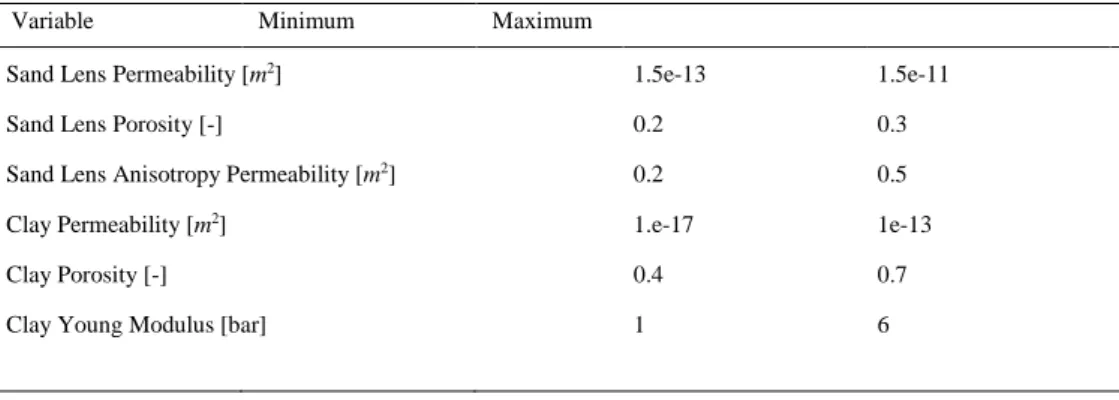
Uncertainties in soil properties are taken into account with the generation of 70 realizations with different soil properties within the parameter ranges defined in Table 3. We consider one injection for three days at an imposed flow rate of 12 m3/d (under ambient pressure-temperature conditions). Sand Young modulus and Poisson's ratio are fixed at 50 bar and 0.35 respectively. Clay Poisson's ratio is set at 0.45.
Table 3: Uncertain parameters and related ranges of values considered for the May of Mecklenburg case study.
Variable Minimum Maximum
Sand Lens Permeability [m2] 1.5e-13 1.5e-11
Sand Lens Porosity [-] 0.2 0.3
Sand Lens Anisotropy Permeability [m2] 0.2 0.5
Clay Permeability [m2] 1.e-17 1e-13
Clay Porosity [-] 0.4 0.7
Clay Young Modulus [bar] 1 6
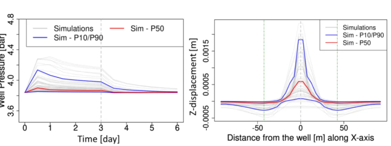
Based on simulations results, several observations are made:
- surface displacements due to injection are mainly centred around the injection point,
- In the ranges of injection rate/pressure considered, the order of magnitude of the displacement, obtained for most of the scenarios, is below 5 mm (Fig. 9).
Considering a fixed solid density value of 2700kg/m3 associated to uncertainties of clay and sand porosity values, the vertical component of Terzaghi initial effective stress is expected between 0.36 and 0.52 bar at 29.5m depth below sea level (see Fig. 6). In scenarios involving overpressures above these values, the integrity of formation has to be considered carefully and implies specific integrity studies with an adapted criterion for soil mechanics and an accurate experimental characterisation. For these reasons the simulations carried out do not allow to conclude with certainty on the damage of the sand lens and clay formation during the planned injection campaign. Therefore, the recommendations provided for the performance of the test are as follows:
- Carry out a (well) test prior to injection to reduce uncertainties on the soil properties and thus better constrain the maximum possible flow rates/pressures under real operational conditions,
- Depending on the results of this test, proceed if possible to inject air in operating ranges allowing at the same time a preservation of the integrity of the geological body considered and the appearance of deformations observable by the monitoring tools used.
Fig. 9. (left) pressure evolution during injection as a function of time obtained by 3D geomechanics simulation; (right) vertical deformations at the surface of the injection site after 3 days obtained by simulation. Noted that no scenario among the 70 simulations considered exceeds the
measurable threshold of 5 mm.
4. Summary
The SENSE project focuses on the development of reliable, continuous, and cost-efficient monitoring techniques based on ground movement detection combined with geomechanical modeling and inversion. This paper presents part of the activities in the SENSE project achieved in the first year of the project. Preliminary results from the In Salah (Algeria) and the Bay of Mecklenburg (Germany) are presented here. New InSAR data from In Salah are used to evaluate the ground movement for the post-injection period and to assess the behaviour of the storage site after completion of the injection phase. Presentation of surface uplift is not only along 2D cross sections but also in 3D, i.e. volume of the uplifted area at the surface. This is an ongoing study.
The analysis of the gravity cores from the Bay of Mecklenburg provided input data for simulating injection operation at this site. The geomechanical simulation carried out by the researchers from IFPEN and NGI showed that the sand and clay/silt layers covering the injection zone may sustain very low overpressure before they fail.
Hence, this magnitude of overpressure may create a seafloor uplift of about few millimeters. These simulation results will be verified during the injection operation planned to be carried out in 2022 using different measurement tools. Experience and learnings from the injection at the Bay of Mecklenburg will help developing the monitoring tools such as fiber optics and ocean bottom landers to measure vertical, static deformation continuously.
Acknowledgements
SENSE (Assuring integrity of CO2 storage sites through ground surface monitoring) project No. 299664, has been subsidized through ACT (EC Project no. 691712) by Gassnova, Norway, United Kingdom Department for Business, Energy and Industrial Strategy, Forschungszentrum Jülich GMBH, Projektträger Jülich, Germany, The French Agency for the Environment and Energy Management, The United States Department of Energy and State Research Agency, Spain. Additional support from Equinor and Quad Geometrics and permission to use data from the Krechba Field by In Salah Gas JV are appreciated.
References
[1] Eide LI. GEOSS, Report on Task SB-05 - Impact Assessment of Human Activities Component C3 – Operational Carbon Capture and Sequestration (CCS) Monitoring System, a feasibility study. Final report GEOSS SB‐05 C3, 2012. 52 p.
[2] Vasco DW, Ferretti A, Novali F. Reservoir monitoring and characterization using satellite geodetic data: Interferometric synthetic radar observations from the Krechba field Algeria. Geophysics, 2008; 73 (6): WA113-WA122.
[3] Morris JP, Hao Y, Foxall W, McNab W. A study of injection-induced mechanical deformation at the In Salah CO2 storage project.
International Journal of Greenhouse Gas Control 2011; 5:270-280.
[4] White JA, Chiaramontea L, Ezzedine S, Foxall W, Hao Y, Ramirez A, McNab W. Geomechanical behavior of the reservoir and caprock system at the In Salah CO2 storage project PNAS June 17, 2014; 111(24):8747–8752.
[5] Mathieson A, Midgley J, Dodds K, Wright I, Ringrose P, Saoula N. CO2 sequestration monitoring and verification technologies applied at Krechba, Algeria. Leading Edge 2010; 29(2):216–222.
[6] Ringrose PS, Mathieson A, Wright I, Selama F, Hansen O, Bissell R, Saoula N, Midgley J. The In Salah CO2 Storage Project: Lessons Learned and Knowledge Transfer. Energy Procedia 2013; 37:6226-6236.
[7] Bohloli B, Ringrose P, Grande L, Nazarian B. Determination of the fracture pressure from CO2 injection time-series datasets. Int. J.
Greenhouse Gas Control 2017; 61:85-93.
[8] White JA, Chiaramonte L, Ezzedine S, Foxall W, Hao Y, Ramirez A, McNab W. Geomechanical behavior of the reservoir and caprock system at the In Salah CO2 storage project. Proceedings of the National Academy of Sciences, 2014; 201316465.
[9] http://global.jaxa.jp/projects/sat/adeos/index.html.
[10] http://www.pnas.org/content/111/24/8747/tab-figures-data.
[11] http://www.drillingcontractor.org/high-cost-subsea-sector-faces-test-of-economics-35798.
[12] http://www.npd.no/no/Nyheter/Nyheter/2017/Oppstart-av-Gina-Krog/.
[13] Trevio RH, Meckel T. Geological CO2 Sequestration Atlas of Miocene Strata, Onshore Texas State Waters, Bureau of Economic Geology, The University of Texas at Austin, 2017, report of Investigations No. 283. doi:10.23867/RI0283D.
[14] Kostecki R, Janczak-Kostecka B, Endler M, Moros M. The evolution of the Mecklenburg Bay environment in the Holocene in the light of multidisciplinary investigations of the sediment cores. Quaternary International 2015; 386:226-238.
[15] Amantov A, Fjeldskaar W, Cathles L. Glacial erosion/Sedimentation of the Baltic Region and the effect on the postglacial uplift. In: Harff J, et al. (eds.), The Baltic Sea Basin, Central and Eastern European 3 Development Studies (CEEDES). Springer-Verlag, Berlin; 2015. p. 53-71.
[16] Jensen JB, Bennike O, Witkowski A, Lemke W, Kuijpers A. Early Holocene history of the Southwestern Baltic Sea: the ancylus Lake stage.
Boreas 1999; 28: 437–453.
[17] Mondol NH, Kizatbay A, Shahid AA. Grain size analysis of core samples from the Bay of Mecklenburg, Germany, Report, Department of Geosciences, University of Oslo. 2021.
[18] Rogstad A, Bohloli B, Quinteros S. SENSE Case Study: Geotechnical testing of clay and sand, Bay of Mecklenburg, offshore Germany.
NGI report 20190570-02-R, 2020.
[19] IFP Energies Nouvelles. PumaFlow 10.0 reference manual, 2018.
[20] EDF. Code_aster, Analyse des Structures et Thermo-mécanique pour des Études et des Recherches. www.code-aster.org. 2020.
![Fig. 1. Overview of SENSE project. (a) to (d) are after [9-12], respectively.](https://thumb-eu.123doks.com/thumbv2/1library_info/5277750.1675890/3.816.73.731.305.500/fig-overview-sense-project-d-respectively.webp)
![Fig. 2. Case studies in SENSE project. (a) In Salah, from [Google Maps], (b) Hatfield Moors, UK, [Google Earth], (c) Bay of Mecklenburg, Germany, (d) location of the High Island field and CO 2 capacity estimates for the coastal region of Texas [13]](https://thumb-eu.123doks.com/thumbv2/1library_info/5277750.1675890/4.816.149.667.101.505/studies-project-hatfield-mecklenburg-germany-location-capacity-estimates.webp)
![Fig. 5. Grain size distribution based on laser diffraction method for gravity core AL527-03, sample #3 (coarse silt), depth 0.25 m (after [8]).](https://thumb-eu.123doks.com/thumbv2/1library_info/5277750.1675890/6.816.132.686.133.365/grain-distribution-based-diffraction-method-gravity-sample-coarse.webp)
![Fig. 6. A depth profile for silt/clay and sand layers, along with the measured and extrapolated material properties [18]](https://thumb-eu.123doks.com/thumbv2/1library_info/5277750.1675890/7.816.123.696.102.423/fig-depth-profile-layers-measured-extrapolated-material-properties.webp)