Finding Common Ground: A Survey of
Capacitive Sensing in Human-Computer Interaction
Tobias Grosse-Puppendahl
1, Christian Holz
1, Gabe Cohn
1, Raphael Wimmer
2, Oskar Bechtold
3, Steve Hodges
1, Matthew S. Reynolds
4, Joshua R. Smith
41
Microsoft Research, Cambridge, UK / Redmond, WA, USA; { tgp, cholz, gabe, shodges } @microsoft.com
2
University of Regensburg, Regensburg, Germany; raphael.wimmer@ur.de
3
Technische Universit¨at Darmstadt, Darmstadt, Germany; oskar.bechtold@stud.tu-darmstadt.de
4
University of Washington, Seattle, WA, USA; jrs@cs.washington.edu, matt.reynolds@ee.washington.edu
ABSTRACT
For more than two decades, capacitive sensing has played a prominent role in human-computer interaction research. Ca- pacitive sensing has become ubiquitous on mobile, wear- able, and stationary devices—enabling fundamentally new interaction techniques on, above, and around them. The re- search community has also enabled human position estima- tion and whole-body gestural interaction in instrumented en- vironments. However, the broad field of capacitive sensing research has become fragmented by different approaches and terminology used across the various domains. This paper strives to unify the field by advocating consistent terminology and proposing a new taxonomy to classify capacitive sens- ing approaches. Our extensive survey provides an analysis and review of past research and identifies challenges for fu- ture work. We aim to create a common understanding within the field of human-computer interaction, for researchers and practitioners alike, and to stimulate and facilitate future re- search in capacitive sensing.
Author Keywords
survey; capacitive sensing; electric field sensing
ACM Classification Keywords
H.5.2. Information Interfaces and Presentation: User Inter- faces - Graphical user interfaces; Input devices & strategies
INTRODUCTION
Capacitive sensing has become so ubiquitous that it is hard to imagine the world without it. We are surrounded by ca- pacitive sensors—from the touchscreens and touchpads on our phones, tablets, and laptops, to the capacitive “buttons”
frequently used on consumer electronics devices and com- mercial equipment. In addition to widespread adoption in
Permission to make digital or hard copies of all or part of this work for personal or classroom use is granted without fee provided that copies are not made or distributed for profit or commercial advantage and that copies bear this notice and the full cita- tion on the first page. Copyrights for components of this work owned by others than ACM must be honored. Abstracting with credit is permitted. To copy otherwise, or re- publish, to post on servers or to redistribute to lists, requires prior specific permission and/or a fee. Request permissions from Permissions@acm.org.
CHI 2017, May 06 - 11, 2017, Denver, CO, USA
Copyright is held by the owner/author(s). Publication rights licensed to ACM.
ACM 978-1-4503-4655-9/17/05$15.00 DOI: http://dx.doi.org/10.1145/3025453.3025808
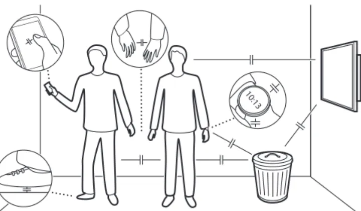
Figure 1. Capacitance ( ) naturally exists between people, their devices, and conductive objects in the environment. By measuring it, capacitive sensors can infer the position and proximity of users and other objects, supporting a range of different applications. However, this inherent capacitive coupling between objects also increases ambiguity of sensor readings and adds noise.
products, the use of capacitive sensing is common in human- computer interaction research, with examples ranging from grasp detection to the estimation of human positioning.
As shown in Figure 1, a plethora of natural capacitances exist between the people, devices and objects in the environment.
It is important to realize that the capacitances shown in the figure are not capacitor components purchased from an elec- tronics supplier. Instead, they represent the natural capacitive coupling between various objects. By measuring these ever- changing values it is possible to infer relative position, motion and more—supporting a multitude of interaction techniques and applications. The small size, low cost, and low power aspects of capacitive sensing make it an appealing technol- ogy for both products and research prototypes. Furthermore, its ability to support curved, flexible, and stretchable surfaces has enabled interaction designers to work with non-rigid ob- jects and surfaces. The human-computer interaction commu- nity has developed numerous interaction modalities using ca- pacitive sensing to operate devices from a distance, including gesture recognition and whole-body interaction.
With such a long history and so many different applications
and instantiations of the technology, it is not surprising that
the field has spawned research across many different do-
mains, and with it a variety of different terminologies. For ex-
ample, the terms capacitive sensing and electric field sensing
refer to the same basic technique. In this paper, we will exclu- sively use the former. Similarly, various terms are used to de- scribe the different types of capacitive sensing systems, such as self-capacitance and mutual-capacitance, both of which in conjunction with x/y grids are commonly referred to as projected-capacitive sensing. Other common terms include capacitive loading, shunt, and transmit modes; passive and active sensing; and static electric field sensing. This varied terminology can make it difficult to recognize the similarities and differences between established capacitive sensing sys- tems, or to understand the contributions of new techniques.
In this paper we summarize and reflect on past work in the field with the aim of providing a resource for others working in the area of capacitive sensing. The contributions of this paper include: (1) a unified taxonomy to describe and classify capacitive sensing technologies, (2) a discussion of guidelines for reproducibility and challenges for future research, and (3) a thorough review and analysis of past work.
BACKGROUND ON CAPACITIVE SENSING History
While some animal species including electric fish and sharks have evolved organs capable of natural capacitive sensing [84], human exploitation only dates back about a century. In 1907, Cremer reported using a string electrometer—a sensi- tive current measuring device—to measure the physical mo- tion of a beating frog heart [39]. The heart was placed be- tween the plates of a capacitor, and as it moved with each beat a change in capacitance was observed. Later, in 1920, L´eon Theremin demonstrated a gesture-controlled electronic musical instrument known as the the Theremin, consisting of two capactively tuned resonant circuits controlling pitch and volume [56]. While capacitive sensing grew to be an impor- tant tool for many engineering applications, such as sensing distance, acceleration, force, pressure, etc., its use in HCI was limited at first. In 1973, engineers at CERN implemented a capacitive touch screen [11], and further work on touch sur- faces grew rapidly in the 1980s and 1990s, including the in- troduction of the multi-touch capacitive tablet in 1985 [121].
In 1995, Zimmerman et al. [236] introduced new capacitive sensing approaches for HCI that went far beyond touch sens- ing on surfaces. With the widespread use of capacitive touch pads, displays, and other interactive devices on desktop, mo- bile, and wearable computers, the impact of capacitive sens- ing has exploded over the past 20 years.
Physical Principles of Capacitive Sensing
Capacitive sensing can be used to estimate physical properties such as touch, proximity, or deformation by measuring the capacitance (i.e., the ability to store charge in an electric field) between two or more conductors. These conductors, often called electrodes, are commonly solid metal parts, but they can also be made from other conductive materials including foils, transparent films (e.g., indium tin oxide, ITO), plastics, rubbers, textiles, inks, and paints. In other cases, electrodes include the human body or objects in the environment.
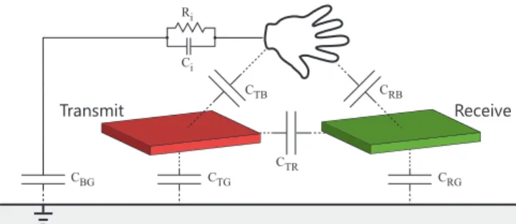
Figure 2 depicts a lumped circuit model consisting of a trans- mit electrode, a receive electrode, part of a human body (to
Ri
Ci
CTB CRB
CTR
CTG CRG
CBG
Transmit Receive
Figure 2. Lumped circuit model of capacitive sensing as introduced by Smithet al.[186]. Depending on the sensing mode, different capaci- tances are controlled or measured.
be sensed), and a simplified view of the natural capacitances between them—each usually no more than several 100 pFs [64, 190]. Most capacitive sensing systems work by measur- ing changes in capacitive coupling between the human body and these transmit and receive electrodes. The role of ground is also important—it simply refers to a common potential to which all of the objects relevant to the system are electrically coupled. Without this common ground, capacitive sensing systems do not have a shared reference, which is critical to operation in many cases. Ground may refer to the electric potential of the floor, as depicted in Figure 1, or to the Earth itself. However, it is important to realize that in some cases, the ground potential is not the floor or the Earth, but simply a local common reference such as the human body itself, or the ground plane of a circuit board.
A capacitance exists whenever two electrodes are separated by some distance. When the conductors are at different elec- tric potentials, an electric field exists between them. Capaci- tance C is the measure of the charge Q (i.e., number of elec- trons) that a capacitor holds when a certain electric potential V is applied: C = Q/V . The SI unit of capacitance is the farad (F). Typical capacitances in HCI applications are on the order of picofarads (pF or 10
−12F) and primarily depend on three properties: the size and shape of the electrodes [133], the distance between them, and the dielectric properties of any material which lies between them. Furthermore, when the electric potentials on the conductors are time-varying, a current known as the displacement current flows through the capacitor. We refer to related work for simple [225] and de- tailed [10] explanations of this general principle.
Capacitance is often measured by observing the displacement current that flows when the electrodes are driven by time- varying voltages with frequencies below 1 MHz [40]. How- ever, some capacitive sensing approaches leverage higher fre- quencies, e.g., by detuning an RFID antenna [108, 124], mea- suring phase differences of signals capacitively coupled to the human body [231], or measuring reflections caused by capac- itive changes along a transmission line [81, 105, 222].
Advantages and Limitations
Capacitive sensors can be used for a wide variety of applica- tions because the electrodes—where the interaction occurs—
can be physically decoupled from the location of the sensing
circuitry. This enables extremely large (e.g., room sized) or
extremely small (e.g., microscopic) electrodes which can be
fabricated from a variety of materials, including curved, flex- ible, and stretchable substrates. They can often be prototyped quickly using everyday materials, then subsequently mass- produced at low-cost. They typically have a minimal height profile and can be hidden under opaque, non-conductive ma- terials, and can be arranged in large, high-resolution scanned arrays. Capacitive sensing is purely electrical, low power, and requires only cheap driving electronics with no moving parts or mechanical intermediaries [87]. A major advantage over other sensing modalities is the ability to sense a wide field of view at very close distances without a lens.
Although this “lens-less” property is a great advantage, it also serves as a limitation since capacitive sensors can- not “focus” their sensing on a specific area, which can re- duce range [73, 190, 225] and introduce ambiguous read- ings [188, 66]. Additional limitations include electromag- netic noise [67, 38, 37] in the face of insufficient grounding, particularly on wearable devices [36]. Furthermore, touch in- teraction using capacitive sensing lacks inherent tactile feed- back and can therefore result in inadvertent activation [87].
A TAXONOMY FOR CAPACITIVE SENSING
In the 1995 landmark paper, Zimmerman et al. proposed a taxonomy to describe types of capacitive sensing by intro- ducing three active operating modes [236]. Over the follow- ing two decades, there has been a significant body of work in the field of capacitive sensing, including new methods of sensing that do not fit into the taxonomy originally outlined.
Having provided a background on capacitive sensing in the previous section, we now define consistent terminology and describe a new taxonomy which extends the classification proposed by Zimmerman et al. This new taxonomy defines a method for clearly grouping and classifying capacitive sens- ing approaches using two independent dimensions, as shown in Figure 3. Sensing techniques can be described as either ac- tive or passive. They can also be grouped into four different operating modes: loading, shunt, transmit, and receive.
Active vs. Passive Sensing
Zimmerman et al. conducted their initial research in the field of active capacitive sensing. In active capacitive sensing, a known signal is generated on the transmit electrode(s), capac- itively coupled onto the body part, and then coupled into the receive electrode(s). The presence and movement of the body part can be sensed by measuring the strength of the signal coupled onto the receive electrode(s). Most of the past work in capacitive sensing has focused on active sensing, including capacitive touch buttons, touchpanels, and touchscreens.
In addition to active sensing, there is a growing body of work using passive capacitive sensing. While active sensing sys- tems must actively generate an electric field, passive sensing systems rely on existing—external or ambient—electric fields which are passively sensed. The active vs. passive termi- nology is used analogously for other sensor types (e.g., pas- sive infrared sensors, which receive infrared energy radiated by warm objects). Passive capacitive sensing is sometimes referred to as ambient or opportunistic electric field sens- ing. Some examples of ambient electric field sources include
Mutual Capacitance Sensing
Transmit Receive
Transmit Receive
Transmit & Receive
Receive Transmit
Receive Transmit Transmit
Receive Self-Capacitance Sensing
Transmit Receive
Active Capacitive Sensing Passive Capacitive Sensing
Loading ModeShunt ModeTransmit ModeReceive Mode
not applicable
Figure 3. Capacitive sensing techniques can be divided into four oper- ating modes: loading, shunt, transmit and receive. Except for loading mode, each mode may be implemented using active or passive sensing.
The dashed line represents the boundary between the sensing system (bottom) and the environment (top).
power lines and appliances, and the low frequency electro- static fields produced by the triboelectric effect when a user moves. Since the sensing system does not control the trans- mit signal, passive systems tend to be less precise and more susceptible to changes in their environment. Despite these limitations, passive capacitive sensing has shown promise in its ability to sense human activities with minimal power and infrastructure [36, 37, 38, 67, 156].
Operating Modes
The operating mode of a capacitive sensing system depends on the relative position between the human body and the transmit and receive electrodes, which in turn defines the rel- ative magnitudes of the capacitances shown in Figure 2. This is independent of the system being either active or passive.
In all cases an electric field is generated between the trans- mit electrode and ground, and a field is sensed between the receive electrode and ground. Although Figure 3 depicts only a single transmit and receive electrode, many capacitive sens- ing systems have multiple transmit and/or receive electrodes.
Loading Mode
Loading mode is the simplest and most common type of ca-
pacitive sensing. Here, the same electrode is used for both
transmit and receive. The body capacitively loads the elec-
trode and causes a displacement current to flow through the
body to ground. As the body gets closer to the electrode, the
capacitive coupling (C
T B) increases and so does the displace- ment current, which allows the system to sense the proximity of the body. Since the transmit and receive electrodes are the same, and are both part of the sensing system, there is no pas- sive variant of loading mode. Due to its simplicity, loading mode is widely used for touch sensing, including capacitive buttons and touch panels. Commercial touch panels that use loading mode are often labeled as self-capacitance sensors.
Electrodes are easy to shield [165, 213, 220], which makes for large detection ranges, e.g., in 3D gesture recognition [63]
or noise-resilient touchscreens [11].
Shunt Mode
In shunt mode, the transmit and receive electrodes are dis- tinct, and thus there is some capacitive coupling between them (C
T R). When the human body is in proximity to the electrodes, it will capacitively couple to both the transmit and receive electrodes with about the same order of magnitude as the coupling between the electrodes (i.e., C
T R≈ C
T B≈ C
RB). This will cause a displacement current to flow through the body to ground (i
BG), and will thus reduce the displace- ment current flowing from the transmit to the receive elec- trode (i
T R). By measuring the decrease in displacement cur- rent at the receive electrode, the body’s proximity can be de- termined. In active capacitive sensing, shunt mode is often used for grid-based touch sensors [9] and interactive surfaces [161]. This is because all combinations of the grid electrodes can be exploited to yield high resolution sensing [73, 236].
As a result, shunt mode is often used for commercial touch panels, which are commonly labeled as mutual-capacitance sensors. In passive sensing, it is possible to detect when the human body shunts an electric field emitted by the infrastruc- ture (e.g., power lines and appliances). This enables indoor localization and gesture recognition [38, 156].
Transmit Mode
Transmit mode is similar to shunt mode, except that the body is very close to the transmitter. This proximity means that the coupling between the body and the transmitter is much greater than the coupling between the body and the receiver or between the transmitter and the receiver (i.e., C
T BC
RB, C
T BC
T R). In this mode, the body essentially becomes an extension of the transmit electrode. When the body gets closer to the receive electrode, the displacement current into the receive electrode (i
RB) increases. In active capacitive sensing, transmit mode allows for a human-mediated detec- tion of an electric field, e.g., to identify the floor tiles being occupied with remote sensors on the ceiling [207]. In passive capacitive sensing, transmit mode corresponds to the class of off-body sensors, e.g., detecting a change in body potential when a person takes a step using remote sensors [4, 197].
Receive Mode
Receive mode is the inverse of transmit mode—the body is very closely coupled to the receive rather than the transmit electrode (i.e., C
RBC
T B, C
RBC
T R). In this case, the body acts as an extension of the receive electrode and can pick up nearby electric fields, using the same operating prin- ciple as transmit mode. In active capacitive sensing, receive mode is mostly used when multiple transmit electrodes emit
different fields [40]. In passive sensing, on-body sensors use receive mode, to enable gesture recognition [37], touch sens- ing [38, 58], and object identification [117].
Transmit + Receive Mode (Intrabody Coupling)
A combination of transmit and receive mode occurs when the body has similar coupling to both the transmit and receive electrodes, yet the direct coupling between the electrodes is much less (i.e., C
T B≈ C
RBC
T R). In this case, the hu- man body acts as a conductor between both electrodes [49], and since this hybrid-mode is common, we refer to it as in- trabody coupling. Past work used many terms to describe this hybrid-mode, including active intrabody communication, body channel communication [235, 7], passive bioelectrical measurements [157], and active bioimpedance sensing [97].
RESEARCH CHALLENGES
Having provided a common context for work in the domain of capacitive sensing via the taxonomy in the previous section, we now describe a number of ongoing research challenges.
We first discuss challenges that generally relate to methodol- ogy and then move on to specific topics.
Towards Better Reproducibility
Throughout our literature review, we regularly observed that reconstructing a particular sensing approach would prove dif- ficult due to missing details (e.g., the number of sensors or the type of grounding). Only 68 of the surveyed papers re- port sensing range (27× touch, 29× <50 cm, 12× 100 - 300 cm). The employed metrics vary widely. Of course, the nec- essary level of detail depends on the type of contribution—
fewer details are needed for new applications of well-known capacitive sensing principles, but new approaches to capaci- tive sensing demand more detailed descriptions.
To enable reproducibility, we suggest that papers describing applications of capacitive sensing include: (1) whether active or passive sensing is used, (2) the operating mode, (3) the number of transmit and receive electrodes, as well as their material and shape, and (4) the hardware and software be- ing used to conduct the measurement (e.g., Arduino using CapLib). We suggest that new approaches in capacitive sens- ing additionally include: (5) how the sensor, the human body, and related objects in the environment are grounded, (6) a de- tailed description of hardware, including a schematic, (7) the sensor operating frequency, (8) the sample or scan rate, sam- ple bit-depth, and any other relevant details that will enable others to understand the physical setup. If proximity is being measured, we suggest that the reported range corresponds to the state in which the detection accuracy for a human body part is expected to be greater than 95% (derived from [102]).
Sensitivity to Grounding
As mentioned earlier, the grounding of the sensor(s) and user(s) is a critical aspect of capacitive sensor behavior.
This is especially important in battery-powered applications, which often rely on a very weakly coupled ground reference, e.g., to measure external electric fields [36, 37, 38, 68, 235].
When battery-powered devices are connected to grounded
measurement equipment or long test leads, the performance
is artificially improved by the enhanced ground coupling, as a small grounded sensor tends to work better than a large un- grounded sensor [6]. Some wearable prototypes in the litera- ture make use of external ground connections while prototyp- ing, but would not work as standalone wearables.
To realize applications that suffer from insufficient ground- ing, two options exist. One is to enlarge the size of the ground plane [68, 235], but that can be a problem for some wear- able applications. The other option is using a sensor with very high input impedance to detect small displacement cur- rents [50, 79]. We refer the reader to additional literature on the various aspects of grounding [68, 100, 176, 202].
Implications for Real-World Deployments
Today’s widely available machine learning models have en- abled researchers to make inferences on potentially high- dimensional capacitive sensor data relatively easily. How- ever, much of this research—particularly N-fold cross- validation applied to data collected in relatively static lab- oratory settings—has treated these learning models as a black box. It is often hard to judge whether these classi- fiers would generalize effectively in a more realistic setting than in the specific experimental conditions reported. The concern is that these models are fragile, and therefore will likely break if any environmental changes occur [179]. Un- fortunately, such changes are inherent in capacitive sensing through varying ground-coupling [119], changing user be- havior over time [180], or environmental noise [38, 37, 225].
Although real-world deployments are very challenging, espe- cially in terms of collecting ground-truth data, they are essen- tial to demonstrate feasibility beyond a controlled lab setting.
As a complement to machine learning, we see a challenge of future research in models that are motivated by the under- lying physics of capacitive sensing, the physical structure of the human body, and the sensing environment. For example, spatial models [66, 67, 168] help recognize the underdeter- mination of a problem [168], and produce inferences that are less dependent on users [198, 138] and environments. Using these models, a spatial representation of the surroundings can be obtained much like a 3D camera [53, 186]. This area of research is often called free space electric field tomography and was extensively researched in the 1990s [190, 186, 188].
Since then, little work has followed on developing spatial models that leverage electric field imaging [66]. A renewed effort around physically-motivated spatial models could en- able capacitive sensing to truly ‘see’ the world, as such mod- els provide an intermediary layer between raw sensor read- ings and machine learning by reconstructing human body parts in full 3D to provide an even richer context.
Support for End-to-End Prototyping
Over the last several years, researchers have made capacitive sensing—particularly electrode design—more accessible by developing systems that support rapid prototyping and evalu- ation. A study by Unander et al. showed good performance using electrodes printed with both silver- and carbon-based ink [203]. New silver nanoparticle [105] and microparti- cle [170] ink technologies now allow electrode shapes and
configurations to be prototyped rapidly. We are also begin- ning to see the emergence of stretchable electrodes [217], which is ideal for wearable applications. Software systems, such as Midas [175] support the integration of electrode pat- terns with sensing electronics. Several works incorporate electrodes into 3D printed structures, enabling fast prototyp- ing [20, 149, 177] and easy personalization [61].
While the integration of electrodes is much easier now than a few years ago, compact integrated end-to-end capacitive systems remain difficult to prototype. For example, Cu- pidMZ [27] and NailO [103] required custom PCB circuitry to achieve wearable form factors. Other researchers have ap- plied off-the-shelf electronic hardware for wearable systems (particularly Arduino [126, 208]), but this comes at the ex- pense of form factor. In the future, we envision electronics prototyping tools (e.g., CircuitStickers [91]) to support the integration of capacitive sensing electronics and electrodes into 2D and 3D printed structures. This would enable better miniaturization and robustness, and thus facilitate real-world deployments and longitudinal studies in realistic settings.
Reducing Form Factor & Instrumentation
Due to the emergence of wearable interactive devices, such as augmented tattoos [98] and finger rings [215], the physi- cal size of batteries is becoming a limiting factor for many capacitive systems [103]. To move beyond batteries as the determining factor for device size, researchers have been opti- mizing power consumption, for example by using low-power passive sensors for motion [36] and touch [45, 58]. However, for many applications, passive sensing does not offer suffi- cient fidelity in the sensor readings. Hence, the opportunity to combine active and passive sensing systems exists, in which the passive sensor runs in a low-power state and enables the higher-power active sensor only when it detects a signal of in- terest [36]. Gong et al. used a similar approach to implement power-efficient indoor localization [57]. Exploring sensible combinations of both sensing types can enhance battery life, enable harvested energy sources, extend perceptive capabili- ties, and allow for smaller form factors in the future.
Besides reducing the form factor of the electronics, it is of- ten hard to achieve the same with electrodes. For exam- ple, in many capacitive indoor localization systems, a sig- nificant amount of instrumentation is needed underneath the floor [15, 194, 205]. Reusing parts of the environmental infrastructure for active sensing seems promising. For ex- ample, by injecting a signal into the power line of a house [148, 195], it can act as a transmit electrode for an indoor localization system. Other unused conductive structures in- clude door knobs [173] or even floating water [41].
Enabling Flexible and Stretchable Applications
The ability to use capacitive sensors on non-rigid substrates
has enabled touch sensing in a number of new application
domains, including wearables. Flexible and stretchable in-
terfaces enable new types of interaction [60, 77] and support
ubiquitous deployments, e.g., in fabric and clothing [8, 30,
152, 185] or directly on the human body [98, 103, 217].
An inherent challenge arises when flexible interfaces are worn in close proximity to the body, as human motion causes substantial capacitance changes between the electrodes and the body [76, 152]. To prevent false activation, it becomes necessary to sense the deformation or motion of the electrode to compensate for artifacts in the signal. This can be achieved by using multiple types of capacitive sensing [58], biphasic electrode configurations [191], or other sensor types (e.g., re- sistive pressure and bend sensors [58, 164]). While the use of electro-optic crystals is largely unexplored in HCI, their sen- sitivity to electric field changes appears promising, especially on or around the human body [50, 183].
Another significant challenge is the fabrication of conductive materials that are durable while still remaining flexible and stretchable. Recent advances in material science and chemi- cal engineering have resulted in conductive polymers for the creation of flexible and stretchable electronics [128], conduc- tive yarns [152], foils [137], liquid metals [44, 128, 125], and non-rigid micro and nano-structures [83, 193]. These new materials are well suited for interfacing with the organic and dynamic contours of the human body. As such techniques become more available, the HCI community should leverage them for creating novel applications in on-body capacitive sensing using flexible and stretchable electrodes.
Unifying Approaches to Interpret Electric Fields
Within buildings, power lines and appliances emit an al- most omnipresent ambient electric field [37, 38, 156]. Sim- ilarly, electric fields generated by mobile devices, such as smartphones [99] and household electronics [117] have been leveraged in passive capacitive sensing systems. An exten- sion of this approach can be used to detect touches and ges- tures around uninstrumented appliances by leveraging unique properties of their operation, e.g., through compact fluores- cent lamps [72] or liquid crystal displays [28].
Electric fields are also produced due to human motion—the result of static charging, explained by the triboelectric ef- fect [23], and by very low frequency changes in the capac- itive coupling between the body and the environment during motion [36, 47, 67, 116, 197]. Furthermore, extremely weak electric fields are produced by the human body itself, includ- ing those generated by the human heart and other muscles.
Although challenging to detect, heart activity has been sensed capacitively at distances of 40–100 cm [79, 157].
The electric field in our environment results from a super- position of fields produced by all the sources listed above and more. To date, most research has drawn from just one of these for specific applications [37, 38, 67, 117, 157, 156]. A chal- lenge arises when analyzing multiple electric field sources with the same technical system. Ultimately, we envision miniaturized devices that detect indoor locations, user identi- ties, user actions, and physiological signals — all at the same time. We also expect future wearables to distinguish between indoor and outdoor activities and to reliably count footsteps.
Enriching Sensing with Communications
In the early 2000s, Rekimoto et al. introduced combining sensing and communications using touch-sensitive surfaces,
clothing, and wearable devices [159, 161]. More recent work has used wearables to communicate with touchscreens for token-based [214, 215] and biometric [97] authentication.
However, the data rate of these approaches is limited by the slow update rates of commercial touchscreen controllers.
While through-body transmissions between surfaces and de- vices been demonstrated using other modalities [160, 219], enabling them using capacitive sensing requires rethink- ing mobile devices as a medium for both sensing touches and emitting signals for two-way communication. A recent project prototyped this by switching the touchscreen scanning on and off, achieving up to 50 bits per second [85]. If touch- screens were to be intentionally designed for the purpose of communication, much higher data rates could result.
On larger interactive surfaces, messages could be encoded and decoded locally in certain areas to exploit spatial corre- spondences in interaction design [161]. Applications range from transferring data from displays to smartwatches or us- ing sensor-augmented tangible objects in proximity to touch- screens for gaming applications. Even when a screen is off, embedded electrodes can act as a hub for intrabody communi- cations of data to other users [235] or touched devices [146].
LITERATURE REVIEW
In this section, we describe the literature review which in- formed our taxonomy and discussion of outstanding research challenges. In the review we focus on novel research on capacitive sensing techniques and applications in human- computer interaction. Thus, we exclude technologies that measure the intrinsic properties of a material (e.g., capaci- tive pressure sensors), as well as uses of commercial sensing systems, such as common touch screens.
In our experience, most HCI-related capacitive-sensing re- search is indexed by ACM and IEEE digital libraries.
Therefore, we conducted an initial full-text search in these databases in June 2016. To avoid overlooking relevant publications, we searched for occurrences of electric field or capacitive together with search terms indicating human- computer interaction (activity, gesture, interaction, move- ment, touch). This search resulted in over 5,900 papers, which we loaded into a custom-developed paper management system. In the next stage, each paper was examined by at least one reviewer. Most papers were dismissed as off-topic as they did not fit the aforementioned criteria. By scanning the referenced literature of the papers matching our criteria, we added another 26 papers. The resulting 255 papers were then reviewed by at least two authors and tagged in various dimensions to allow us to identify trends among all papers.
Overall, our literature review comprises the 193 papers that
we identified through our filtering process. Tagging all pa-
pers has allowed us to identify trends across this large body
of work. Unsurprisingly, the majority of papers (125/193)
present novel applications of capacitive sensing, while 100
papers include a hardware contribution. About one quarter
of all papers present a quantitative study (54) or an algorithm
contribution (45). About 32 papers include a model of the
electrical properties, while 12 present simulation results. In-
terestingly, 22 papers present toolkits for capacitive sensing, but only 3 of them are open-source [64, 175, 225].
As we noted before, a multitude of terms has been applied to different types of capacitive sensing; however, the existing HCI literature shows significantly less variance. While many surveyed papers do not explicitly mention the sensing princi- ple used, 75 papers use the generic term “capacitive sensing,”
while 11 of them use the term “electric field sensing.” Be- sides these terms, a long but thin tail of alternative terms exist, such as “skin potential level,” “projected capacitance,” “elec- trostatic induction,” and “human body electric potential.”
Earlier in the paper, we presented a taxonomy for describ- ing and classifying the different types of capacitive sensing.
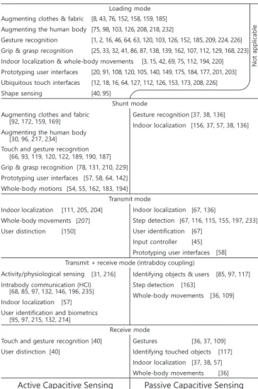
We have grouped much of the past literature using our tax- onomy and distinguishing by application domain to present an overview of the research space, organized as in Table 1.
As shown in the table and detailed throughout this section, capacitive sensing has been used to enable a wide variety of HCI applications using a variety of sensing techniques.
Sensing Goal Touch Sensing
The most ubiquitous form of capacitive sensing is the touch- sensitive surface and the touchscreen [9], which emerged from early prototypes in the 1970s [11]. Through the 1980s, the HCI community made significant advancements by devel- oping custom hardware to enable multi-touch screens [121].
Later projects, including SmartSkin [161] and Diamond- Touch [40] have highlighted the interaction potential of this emerging technology. More information on the large space of capacitive touch sensing can be found in surveys by Bux- ton [21], Barrett and Omote [9], and Schoening et al. [178].
Due to the broad availability of commercial touchscreen de- vices today, HCI research on fundamentally new touchscreen hardware is rare. Some exceptions exist, such as interactions based on a combination of capacitive sensing techniques in a novel device (e.g., Pretouch [86] on a Fogale display) or new low-latency touch screens [122].
Touch sensing on surfaces other than displays has been in- vestigated to create more expressive computing devices and peripherals, including mice [210], keyboards [13, 45], tablet PCs [88], pens [192], and tangibles [52, 68, 118]. Sensors distributed around the screen can help to avoid visual occlu- sion [139] or to enable interaction on near-eye displays [130].
As high-resolution touch input has become ubiquitous for desktop and mobile computing, lower resolution capacitive touch solutions have also been widely used in wearable tech- nologies. Some wearable applications include touch surfaces on belts [43], finger rings [26, 218], devices worn near the ear [126], on fingernails [103], or even implanted underneath skin [96]. Following the emergence of flexible conductive materials, such as conductive paint and yarn, wearable inter- faces have made hair extensions touch-sensitive [208] and en- abled touch sensing on clothing [76, 92, 152]. Sensing touch input directly on the human body has recently been explored through augmenting skin with tattoos [98, 217].
Useridentificationandbiometrics [95, 97, 215, 132, 214]
Loadingmode Augmentingclothes &fabric [8, 43, 76, 152, 158, 159, 185]
Augmentingthehuman body [75, 98, 103, 126, 208, 218, 232]
[1, 2, 16, 46, 64, 63, 120, 103, 126, 152, 185, 209, 224, 226]
[25, 33, 32, 41, 86, 87, 138, 139, 162, 107, 112, 129, 168, 223]
[3, 15, 42, 69, 75, 112, 194, 220]
[20, 91, 108, 120, 105, 140, 149, 175, 184, 177, 201, 203]
[12, 18, 16, 64, 127, 112, 126, 153, 173, 208, 226]
[40, 95]
Gesturerecognition Grip &grasprecognition
Indoorlocalization &whole-bodymovements Prototyping userinterfaces
Ubiquitoustouch interfaces Shape sensing
Notapplicable
Augmentingclothesandfabric Augmentingthehuman body Touch and gesturerecognition Grip &grasprecognition Prototyping userinterfaces Whole-bodymotions
Gesturerecognition Indoorlocalization
Indoor localization
Userdistinction
Indoorlocalization Stepdetection Useridentification Inputcontroller Prototyping userinterfaces Activity/physiologicalsensing
Intrabodycommunication (HCI) Indoorlocalization
Identifyingobjects & users Step detection Whole-bodymovements Userdistinction
Whole-body movements [92, 172, 159, 169]
[30, 96, 217, 234]
[66, 93, 119, 120, 122, 189, 190, 187]
[150]
[207]
[111, 205, 204]
[31, 216]
[58]
[68, 85, 97, 132, 146, 196, 235]
[40]
[40]
[36, 37, 109]
[117]
[37, 38, 57]
[36]
[57]
[163]
[36, 109]
[85, 97, 117]
[67, 136]
[67, 116, 115, 155, 197, 233]
[67]
[45]
[78, 131, 210, 229]
[57, 58, 64, 142]
[54, 55, 162, 183, 194]
[37, 38, 136]
[156, 37, 57, 38, 136]
Touch and gesturerecognition Gestures
Identifyingtouchedobjects Indoorlocalization Whole-bodymovements
Active Capacitive Sensing Passive Capacitive Sensing
Shuntmode
Transmit mode
Transmit+ receive mode (intrabdoy coupling)
Receivemode
Table 1. Past work on capacitive sensing grouped using our taxonomy.
Most works apply active loading mode, whereas we found few papers that use active receive mode.
Capacitive sensing has also been used to detect user interac- tion with the environment. Active sensing approaches instru- ment objects in the environment to sense user input, including plants [153] and household objects, such as door knobs [173].
Other work has passively sensed electric fields that are gener- ated by the power lines and appliances in the environment, and monitored changes to observe touch events on instru- mented objects [45, 58], walls [38], or appliances [117].
User Grip & Grasp
Beyond sensing mere touch locations, capacitive sensors yield a rich enough signal to determine the shape of grasps on instrumented objects and devices [221]. Since capacitive sensors can adapt to arbitrary surfaces, researchers have sens- ing for grasp detection on mice for gesture input to desktop computers [87, 210] and interactive balls [78, 199].
In recent years, research has focused on mobile devices that
detect the user’s grasp to support interaction [32, 33, 107, 198,
223]. To distinguish between commonly-used grasps, a rela-
tively large number of sensors is often needed. Either high-
resolution active shunt mode grids [88, 131, 192, 199, 210,
229] or a multitude of loading mode sensors [33, 107] de-
liver enough information to determine grasp. Some specific applications have used fewer sensors, for example to adapt the screen rotation depending on the user’s grip [32], to start an application [118], or to sense a small number of different grasps through only a few sensors [223]. While the sensor data is often fed into a machine-learning classifier to estimate the grasp, specialized spatial sensors deliver the actual shape of grasps from estimated finger and hand proximities [86].
Sensing Tangibles on the Touchscreen Surface
Recognizing tangible objects on the surface of touchscreens has been shown to enrich the interactive experience by pro- viding physicality [24]. These tangible interfaces are often realized by adding passive components to the bottom of the tangible. Fake touch points that spread across the bottom surface of the object allow the touchscreen to detect the ob- ject’s position, orientation and identity it much like a 2D bar- code [24, 101, 113, 161]. However, this approach only works while a user is touching an object and thus a capacitance to ground is present through the body. Voelker et al. demon- strated a modified approach that bridges multiple touch points to enable ungrounded detection of tangibles [211, 212].
To communicate dynamic information between devices, touch events have been triggered on the screen using nearby voltage sources, e.g., to perform biometric [97] or token- based [215] authentication. While the former sends a sig- nal through the user’s body, the latter is part of the class of direct capacitive communication. Similarly, Yu et al. uses active tags to encode information with high-voltage signals, which touchscreens receive when tags are placed on the sur- face [230]. Today’s commercial styli are similar in their im- plementation, such as the Atmel maxStylus [5] or the Mi- crosoft Surface Pen [135]—both use the capacitive sensor of the touch device for detecting and distinguishing touch from pen input. These devices are effectively grounded through the user when touched, and they transmit a signal through an electrode that couples to the screen.
3D Gesture Sensing
Capacitive sensing can be extended beyond surface interac- tions to enable proximity-based recognition of objects, which has been explored for 3D gesture interaction since the mid- 1990s [236]. Early gesture recognition systems include the the compact Field Mice [187] and Lazy Fish [190] platforms, which evolved into the modular School-Of-Fish [188] plat- form. The latter detects gestures at distances up to 1 m [190].
This early work focused on gestural interactions for ma- nipulating 3D objects [187], new forms of musical expres- sion [144], and enabling tangible interactions [190].
More recent work has investigated generic proximity-sensing surfaces that sense 3D input to control computers [1, 2, 14, 16, 48, 66, 78, 120] and home automation systems [62]. More specialized deployments recognize proximity-based gestures in cars [17, 46] or on clothing [185]. Proximity-sensing sur- faces deployed on or near displays [86, 119, 167, 168, 190]
enable smartphones to show context-dependent menus before the touch contact [86], launch apps based on grasp [25], or detect 3D gestures above the surface [119]. Systems that op-
erate near displays are particularly challenging due to noise and nearby-conductive structures [224].
Indoor Localization
Active sensing approaches for indoor localization commonly involve embedding large loading mode electrodes under- neath floor tiles to determine on which tile the user is stand- ing [15, 57, 194]. Alternatively, the entire floor can act as a single transmit electrode using transmit mode. In such a con- stellation, the signal from several receive electrodes around the environment has been shown to determine the user’s lo- cation [206, 207]. To reduce the required instrumentation, signals can be injecting directly into existing powerlines in place of dedicated transmit electrodes [19].
Similarly, some passive sensing systems leverage the ambi- ent electric fields generated by the power lines and appli- ances to estimate the user’s location [38, 57, 136, 156]. As these systems rely on ambient fields, they require prior train- ing and are sensitive to changes in the environment. By detecting changes in the characteristic body electric poten- tial during walking motions [47], passive capacitive sensors can detect indoor locations [67, 136], recognize gait pat- terns [36, 115, 116, 197, 233], or identify users [67].
Posture & Whole-Body Tracking
Capacitive systems that infer a user’s pose often operate on the same principles as the indoor localization systems mentioned above. In an instrumented space, researchers have implemented body-pose tracking using active transmit mode [204, 207] and loading mode [220] sensing. Dance and athletics have been captured by transmitting signals among multiple sensor nodes [6]. Wearable systems usually offer a more specialized way of determining postures or motion.
Using signal fingerprinting, ambient electric fields generated from the power lines have been used to passively recognize postures [38] and whole-body movements [37]. Passively perceiving changes in body electric potential through move- ment has been used to recognize steps [36, 67, 155, 163] and arm movements [36, 155]. By observing changes in body impedance, researchers have detected different poses [85].
User Identification and Biometric Sensing
Beyond detecting locations, it is often desirable to identify which user caused a touch. Systems have thus reused touch as a channel to transmit the identity of a wrist token to the touch device for authentication and personalization [132, 159].
Other systems distinguish simultaneous users without the
need of a wearable token. Grosse-Puppendahl et al. ’s ceil-
ing sensors reconstruct users’ electric potentials and distin-
guishes them from the characteristic changes while walk-
ing [67]. DiamondTouch configures the seats around the ta-
ble as receive electrodes and determines the user that caused
a touch through a receiver in each seat that observes the ta-
ble’s signal upon touch [40]. Similarly, measuring the user’s
impedance to ground upon touch has been shown to enable
distinguishing two simultaneous users [80]. The same ap-
proach can determine if two wearable devices are on the same
body through intrabody communication [149].
To identify and authenticate users from a touch using the user’s fingerprint, a capacitive sensor requires an extremely high density sensor array [182]. Such capacitive fingerprint scanners are typically dedicated components using swipe and area sensors for authentication on and across [94] devices.
Although in wide use, such scanners cannot currently be made from transparent materials for integration into a screen.
To prototype interactions with touch devices that identify each user upon touch, Holz and Knaust demonstrated a wrist- band that measures biometric features and transmits them to the touchscreen using intrabody communication [97].
Physiological Sensing
In addition to sensing biometrics for user identification and authentication on touchscreens, capacitive sensors have been used to create wearable devices that sense physiological sig- nals during wear. Capacitive sensors have been embedded into clothing for detecting breathing [31], swallowing [30], and drinking [31]. Passive sensors can detect gait patterns in- cluding limping [36, 67, 115, 116]. Capacitive sensors have also been used to detect arm [232] and facial [158] muscle activity as an alternative to electromyography. These sys- tems work by sensing changes in the proximity of the skin to a wearable during muscle flexion. Capacitive textile arrays have also been embedded into clothing to sense gestures and movement detection in patients with limited mobility [185]
and other health-related applications [200].
Instrumenting Everyday Objects
Clothing. The integration of capacitive touch sensors into clothing was first explored in 1998 [143]. Researchers have since used this approach to implement health applications [8, 30, 185] and ubiquitous touch interfaces [43, 76, 92, 143, 152]. Sensors have thereby been placed on pants [172, 185], belts [43, 196], shoes [145], gloves [104, 209], and jack- ets [152]. However, manufacturing techniques and long-term deployments (i.e., surviving wash cycles) remain open re- search areas for such systems [152].
Furniture. Due to its simplicity and ease of shielding [69, 226], active loading mode is dominantly used for posture and touch recognition on furniture. Researchers have thereby augmented couches [69, 110], bath tubs [89], beds [42], chairs [112, 236], lamps [72], and tables [16, 90, 226] with capacitive sensing. Less conventional applications include fabric-based sensors inside bed sheets to enable low-power communication with wearable devices [68] or to recognize sleep postures [169].
Rooms. Room-size deployments of capacitive systems are often used for indoor localization, but have also been used for interactive art installations [18, 151] and gait recogni- tion [115, 116]. To ease with the deployment of large form factors, electrodes can be printed on flexible rolls [57].
Cars. Detecting the presence of adult passengers to ensure the safe deployment of airbags is a common application of capacitive sensing [54, 55, 202]. Other applications have fo- cused on user distinction [150] and gesture recognition using sensors in the steering wheel [46, 166] and armrests [17].
Musical Instruments. The thin profile of capacitive electrodes allows them to be unobtrusively integrated with existing mu- sical instruments. Paradiso et al. first explored this with a cello bow and an augmented baton [144], and subsequent work has been applied to guitars [59, 70] and pianos [134].
Sensor Design and Fabrication
Electrode design is a fundamental aspect of prototyping ca- pacitive sensing applications. Besides traditional materials, such as copper or other metal plates, a growing variety of electrode designs have been made from conductive inks and paints as shown in Table 2. Through the use of inkjet print- ing, electrodes on both, flexible and cuttable substrates can be prototyped [57, 58, 105, 108, 141, 142]. As an alternative to inkjet printing, vinyl cutters can create customized adhe- sive electrodes [175] or cut a substrate for composite elec- trode materials, e.g., conductive tattoos [98]. To build larger sensing systems, conductive paint can be used to apply elec- trodes on wall surfaces [18, 174]. To bridge the resulting gap between electrodes and electronics, CircuitStickers use pre-fabricated adhesive electronic components [91].
With the emergence of 3D printing, researchers have started to explore prototyping objects with integrated capacitive elec- trodes. For example, capacitive sensing can be enabled on printed objects by filling tubes inside the objects with conduc- tive inks [174], interrupting the print process to integrate elec- tronics [181] or combining conductive and non-conductive print materials [20, 123, 177]. Conductive yarns and fab- rics open new possibilities for flexible electrode design, e.g., the integration into clothing [8, 30, 92, 152, 185]. Conduc- tive paint has also been applied to retrofit existing clothing with sensing capabilities [76, 200]. The durability of textile- based electrodes remains a challenge (e.g., to support multi- ple washing cycles) [152].
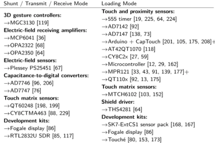
Sensing electronics
The choice of electronics depends primarily on the operating mode as shown in Table 3. Hardware for the shunt, trans- mit, and receive modes is similar and usually consists of an oscillator connected to the transmit electrode to generate an electric field, and an amplifier and analog-to-digital converter (ADC) connected to the receive electrode. In loading mode,
Copper- highly conductive, flexible
→Wire[15, 45, 161, 169, 197]
→Foil [32, 117, 146, 171, 78, 236]+
→Vinyl [175]
→Plate [64, 66, 120, 226, 224]+
→PCB
→Rigid [16, 35, 40, 158, 229]+
→Flex [25, 107, 138, 192, 210]+
→Tape [42, 64, 132, 162]
→Ink [59, 57, 58]
→Paint [18]
→Metalization [208]
Gold- non-corrosive, skin-friendly
→Gold leaf [98]
→Gold coating [11]
Aluminum- flexible, high availability
→Foil [70, 147, 196, 202]
→Mylar [190]
Silver- non-corrosive, flexible
→Ink [76, 87, 105, 108, 203]+
→Thread/Yarn [185]
→Plate [67]
Carbon- enabling electrical conductivity
→Ink [203]
→Carbon-filled PDMS (cPDMS) [217]
→Filament [20, 123, 177]
ITO- transparent electrodes [64, 119, 199]
Anisotropic materials- directing e-fields
→Anisotropic ’Zebra’ tape [91]
→Anisotropic ’Zebra’ rubber [24]
Other materials
→Water [41, 173] & Plants [153]
→Ionized gas [72]
→Metal objects [43, 68, 173, 207, 226]+
→Electro-optic crystal [50, 183]
→PEDOT:PSS [64, 142]
Table 2. Materials used for capacitive electrodes: Copper and silver are the most prominent materials for realizing capacitive electrodes.
Shunt / Transmit / Receive Mode Loading Mode
3D gesture controllers:
→MGC3130 [119]
Electric-field receiving amplifiers:
→MCP6041 [36]
→OPA2322 [68]
→OPA2350 [64]
Electric-field sensors:
→Plessey PS25451 [67]
Capacitance-to-digital converters:
→AD7746 [96, 206]
→AD7747 [76]
Touch matrix sensors:
→QT60248 [198, 199]
→CY8CTMA463 [88, 229]
Development kits:
→Fogale display [86]
→RTL2832U SDR [85, 117]
Touch and proximity sensors:
→555 timer [19, 225, 64, 224]
→AD7142 [92]
→AD7147 [138, 73]
→Arduino + CapTouch [201, 105, 175, 208]+
→AT42QT1070 [118]
→CY8C2x [27, 59]
→Microcontroller [12, 29, 162]
→MPR121 [33, 43, 91, 139, 177]+
→QT110x [92, 13, 175]
Touch matrix sensors:
→MTCH6102 [103, 152]
Shield driver:
→THS4281 [64]
Development kits:
→SK7-ExtCS1 sensor pack [168, 167]
→Fogale display [86]
→Touch´e [80, 153, 173]
Table 3. Electronics hardware used in capacitive sensing literature.