Semi-automatic generation of full CityGML models from images
Kerstin Falkowski, J¨urgen Ebert – Work Group Software Technology {falke|ebert}@uni-koblenz.de
Peter Decker, Stefan Wirtz, Dietrich Paulus – Work Group Active Vision {decker|wirtzstefan|paulus}@uni-koblenz.de
University of Koblenz-Landau, Universit¨atstr. 1, 56070 Koblenz, Germany
1
IntroductionThe City Geography Markup Language (CityGML)1 is a common information model for the representation of 3d urban objects and an official standard of the Open Geospatial Consortium (OGC)2 since August 2008 [6]. Besides represent- ing geometry only, CityGML can also be used to model topological and semantic properties of 3d city models and to attach appearance information like textures.
We call models with these featuresfullCityGML models.
The additional information of full CityGML models allows for powerful queries in the context of augmented reality and pose tracking applications. Thus, CityGML is also suited to work as an interchange format in semantics-based processing of 3d objects in computer vision applications.
In this paper we report on an experiment to semi-automatically generate 3d models of buildings from a pair of images captured by a single calibrated color camera and to transform them into an internal graph model. After some exemplary algorithmic manipulations on the graph the result is exported using the CityGML format. This case study shows that in principle full CityGML models might be generated automatically with all their facets.
Generating a model from images instead of modeling it from scratch by some graphical modeling tool has plenty of advantages. Taking photos is much easier than reconstructing a model from accurate blueprints, and often photos are even the only source for modeling. Furthermore, the textures come along for free.
1.1 State of the art
Reconstruction of buildings and urban scenes from images has been worked on by several groups with different focuses during the last decade. The authors in [2] describe a complete system to model architectural scenes from images with a strong focus on photo-realistic rendering. They represent the reconstructed scene as a hierarchy of parametric polyhedral primitives with spatial relationships. The
1http://www.citygml.org,http://www.citygmlwiki.org
2http://www.opengeospatial.org/standards/citygml
authors in [3] report on a system which uses a model of buildings to aid the re- construction process. Their model is based on a collection of walls which contain sets of volumetric primitives corresponding to architectural features as walls and windows. Recently, the focus has shifted towards generating semantic models, which can be used for many more tasks beyond visualization. CityGML offers the possibility to represent such a model.
Besides CityGML there are other languages for the representation of 3d urban objects. One common approach is the OGC standard Keyhole Markup Language (KML)3. CityGML as well as KML use the OGC standard Geography Markup Language (GML)4 [1] for geometry representation. KML is often combined with the COLLADA5 exchange format for 3d assets. Another 3d modelling language isExtensible 3D (X3D)6, the successor of theVirtual Reality Modeling Language (VRML)7 standard.
There is a huge gap between computer graphics models and geographic infor- mation systems models. Computer graphics models have geometric, low-level topological and appearance information and are efficiently processable; but they have no semantics. In contrast to that, some geographic information systems mod- els, like CityGML, include semantic, geometric, topological and appearance in- formation simultaneously; because of their XML base, they are good interchange formats. But they are not processable efficiently enough in large applications.
Thus, a more efficient internal representation is needed for further processing.
CityGML4j8 is an open source Java API for reading, processing and writing CityGML files. But, in contrast to our approach CityGML4j works on the original CityGML schema using JAXB.
Currently there is no approach for the creation of 3d urban object models, that can represent semantics and is efficiently processable simultaneously. Moreover there is no approach for the recognition of urban objects from images leading to such model.
2
CityGML model generationThis paper describes a generation process which extracts the 3d geometry from a pair of images (subsection 2.1). The generation process is exemplified in the con- text of building reconstruction for GIS applications. Several pictures of a building are taken and the task is to derive a full CityGML model thereof. Then, the ex- tracted information is combined in an internal integrated graph model (subsection 2.2). This model is improved to a full model by all kinds of model manipulations (subsection 2.3). Finally, the model is exported as a full CityGML-model which
3http://www.opengeospatial.org/standards/kml
4http://www.opengeospatial.org/standards/gml
5http://www.khronos.org/collada
6http://www.web3d.org/x3d
7http://www.w3.org/MarkUp/VRML
8http://opportunity.bv.tu-berlin.de/software/projects/show/
citygml4j
Figure 1: Overview on the Generation Process
can be handed to other tools for further processing (subsection 2.4), e. g. it may be rendered by some appropriate viewer. Figure 1 gives an overview on the whole process.
2.1 Extracting geometry from images
To be able to reconstruct 3d geometry from two images, one has to find corre- sponding features in both of them. Since it is our goal to reconstruct a building, these features should be relevant to its geometry. If the correct features are chosen, very few will suffice to reconstruct a large part of the geometry.
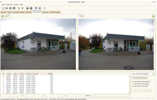
Extraction of feature points. Since automatic detection of suitable features like corners at the top and bottom of buildings or corners of windows is rather difficult, we chose to do it semi-automatically in this case study. Hugin9 turned out to be an excellent tool for marking corresponding point features in a pair of images with automatically improved subpixel accuracy (figure 2).
Reconstruction of the relative camera poses. Given corresponding fea- ture points, the pose of the camera can be computed. Therefore the resulting hugin files are parsed and the subpixel accurate pixel coordinates of corresponding points are extracted. These correspondences are used to estimate a fundamental matrix F. We use the normalized eight point algorithm [7] since we can guaran- tee to provide a sufficient number of points. Because the features were selected manually, we do not need to worry about outliers.
Using the previously acquired calibration matrix K for our camera, we can extract the essential matrixEfrom the fundamental matrix: E =KTF K.
The essential matrix is then decomposed into a rotation and a translation up to a scalar factor: E = λ·[t]×R. The rotation matrix R and translation vector t describe the relative orientation and position of the second camera with respect to the first camera, assuming the first cameras projection matrix to beP1 =
I 0
. The factorization ofEis not unique but yields a translation vector with unknown sign, as well as four possible rotation matrices. Two rotation matrices can be
9Hugin is a photo stitcher invented to connect single photos into one large panorama.
http://hugin.sourceforge.net
Figure 2: 2d point correspondences in Hugin.
discarded since their sign would lead to det(R) = −1. From the remaining four possible solutions of R and t we have to choose the correct combination by de- termining the case in which a single triangulated point (see equation (1) ) lies in front of both cameras [8].
The resulting projection matrix of the second camera is: P2 = R t
.
Reconstruction and grouping of 3d points. Having obtained both pro- jection matrices of the cameras this way, we can reconstruct the 3d coordinates of a world point w˜w from its projectionsp˜i and q˜i by doing a triangulation with minimal squared backprojection error:
˜
ww= argmin w˜w
kP1w˜w−p˜ik2+kP2w˜w−˜qik2 (1) This equation can be linearized with respect tow˜w and solved in a single step using singular-value decomposition (SVD) to compute the optimalw˜w.
This process results in a 3d point set containing all world points arising from correspondences marked with hugin. We visualize them in our OpenGL based PointsToStructure tool with free camera movement where geometric primitives are assembled and annotated manually with rough semantic descriptions like ”wall”,
”roof”, ”ground”, ”window”, . . . . Each of the polygons describes a part of the buildings geometry and has an additional list of 2d positions, representing the building’s wall appearance in terms of texture coordinatesconcerning one of the input images.
If the world coordinates of a point are changed in the later process of model im- provement (section 2.3), a new correct texture coordinate can easily be computed by projecting the new point to one of the images using the projection matrices acquired during camera pose estimation.
2.2 Building an integrated model
After extraction, all information is composed to an integrated model which is kept as a TGraph data structure. This model contains geometric, topological, semantic and appearence information. The TGraph is compatible to CityGML, andimporterandexportercomponents from and to GML/CityGML models exist.
After its composition, the exemplary integrated model is a city model contain- ing one building with an explicit level of detail 1 (lod 1)geometry. It consists of a set of faces, representing the building’s parts. It has also got an explicitappear- ance in terms of a surface data object relating one of the input images to texture coordinates for every building part. Furthermore, it is annotated by an implicit semanticsin terms of the given semantic key words.
TGraph technology. TGraphs [4] are directed graphs whose vertices and edges are typed, ordered and attributed. They are a versatile representation for semantically annotated and attributed geometric models. The combination of a graph API (JGraLab) with agraph query language(GReQL) and amodeling ap- proach for graphs and graph schemas (grUML) provides a basis for definition, creation and efficient processing of models.
The TGraph approach supplies a technology which supports the implementa- tion of various model processing components (section 2.3). The information kept in the graph is formally defined by a graph schema.
Integrated model schema. Theintegrated TGraph schemais oriented at the CityGML schema 1.0 (since it will be used for importing and exporting CityGML data) but it extends the tree-like XML schema by additional concepts and gen- eralizes it. Since a subset of UML is used, its modeling power is much higher than XML Schema. The schema (meta-)models the four relevant aspects of urban objects explicitly, namely geometry, topology, semantics, and appearance. This explicit representation allows for an automatic model refinement.
Thesemantic partof the integrated model schema is based on the semantics of four different CityGML modules: Core, Building, CityObjectGroup and Gener- ics. Most of the entities from these modules are modeled in the integrated model schema as well. In contrast to the CityGML schema, the relations between two entities always have meaningful rolenames at both ends.
Thegeometric and topological partof the integrated model schema is not based on GML. It represents geometric objects by a boundary representation [5, 9].
These data are modeled as a vertex-edge-face-graph (v-e-f graph) similar to the well-known highly efficientDoubly-Conntected Edge List (DCEL)representation [10]. This structure consists of3d pointsand3d facesconnected by3d edges. The geometric information is encoded in the attributes of the 3d points, the topological information is represented by the relations between the geometric entities.
The appearance part of the integrated model uses the necessary concepts of the CityGML appearance module. Because of the structure of the TGraph the different kinds of surface data (material, various kinds of textures) can directly be connected with the 3d faces, they shall be applied to.
The integrated model schema was developed (and therefore can be processed) using TGraph technology. The schema was modeled in grUML in some UML tool and exported to XMI, and the corresponding Java files were generated auto- matically. The three schema parts are modeled in three different grUML packages and thus are generated into three Java packages. The schema is still under con- struction, but because of the TGraph technology it is easily modifiable and each of the three parts can be exchanged by different variants.
In spite of some differences to the CityGML schema we are still able to im- port and export CityGML models that match the profile CityGML [Appearance, Building, CityObjectGroup, Generics]10.
2.3 Processing the integrated model
There are a lot of different activities that can be carried out on the integrated model.
(1) First of all, the integrated model has to be created, where we distinguish between model import,model generationand incremental model creation. In the context of our case study wegenerate the initial integrated model, consisting of a city model with one building supplemented by the recognized surfaces using the TGraph API.
(2) After its creation there are basic refinement activities for the integrated model. One can verify the existence of mandatory attributes and element parts and add them automatically. Furthermore one can check the existent attribute values and element parts and correct them automatically.
(3) Then, the integrated model can be improved, where we distinguish between geometric,topological, andsemantic model improvement.
(3a) The first step is always topology supplementation. This means that every 3d point is connected directly to all its adjacent 3d points and every 3d face is connected directly to all its adjacent 3d faces. This activity is important, because most of the following processing steps are based on computational geometry al- gorithms that assume a complete topological information.
(3b) Another step is geometry correction. In the context of our case study we test the planarity of all 3d faces and make them planar, if they are not, by using an appropriate approximation algorithm. Moreover, we test the 3d faces whether they are almost square and make the properly squared if they are not.
(3c) The next step isgeometry supplementation. In the context of our case study we test if there are incomplete cuboids and complete them by adding mirrored inverted faces.
(3d) Based on topological and geometric model improvement there can also some semantic model improvement be done, where we distinguish between se- mantic entity supplementationandsemantic attribute computation. In the context of our case study we added boundary surfaces for all 3d faces that were added to the buildings geometry during geometry supplement.
10In CityGML profiles theCoremodule is not mentioned because it belongs to every profile.
Figure 3: Semi-automatically generated CityGML model of a building, lod 1 (left), lod 2 and 3 semantically colored and partly textured (right) (4) Another activity is model transformation, where we distinguish between geometry transformation and semantic transformation. A geometry transforma- tion could be the triangulation of the model geometry, a semantic transformation could be the transformation of the CityGML like semantics part into a proprietary ontology.
(5) An activity that has to be carried out many times during all other model processing tasks ismodel analysis. Based on TGraph technology we can traverse and analyze the integrated model during runtime using the Java graph API and/or GReQL queries.
(6) After this processing the integrated model or parts of it can be stored persis- tently bymodel export, in this case to a CityGML format. Using the CityGML ex- porter one can decide, whichappearancesand which levels of detail (lod)should be exported. Currently we can process the CityGML lods 1, 2 and 3.
All mentioned model processing activities are implemented as (atomic) com- ponents in a Java-based lightweight component model.
2.4 Exporting the CityGML model
After model refinement the integrated model contains one building and a bounding box for the whole model. The building has a lod 1 geometry and an appearance.
Furthermore the building contains an explicit semantics in terms of lod 2-3 seman- tic elements. The lod 2 geometry consists of building walls, a building roof and a building ground, represented by those polygons of the lod 1 geometry that were annotated with the simple semantic keywords ”wall”, ”roof” or ”ground”. The lod 3 geometries consist of windows, represented by those polygons of the lod 1 geometry that were annotated with the semantic keyword ”window”. Moreover it has newly inferred building walls with an lod 1-2 geometry and an appearance.
At last, there are a lot of explicit building attributes, like height and width of a building wall, the surface area of a building wall, and so forth.
As a proof of concept a semi-automatically generated integrated model (from two images) of a buildings was exported to CityGML and visualized using the IFC-Explorer for CityGML11 of Forschungszentrum Karlsruhe (figure 3).
11http://www.iai.fzk.de/www-extern/index.php?id=1570
3
Conclusion and future workThis paper sketched a procedure which leads from two images to an integrated model of an urban object. This model contains geometric, topological, seman- tic, and appearance information that can efficiently be analyzed, improved, trans- formed and exported in different formats, e. g. CityGML.
There still are several research activities to investigate. One near-term activ- ity concerningobject recognitionis the combination of some Hugin functionality with the PointsToStructure-Tool to one integrated software, using the Hugin-API.
Another one is object recognition and 3d reconstruction using more than two im- ages. A long-term goal is making the object recognition fully automatic. An- other near-term activity concerning model processing is the enhancement of the integrated model schema and its im- and exporter for the processing of the base profile CityGML [full]. A related activity is the integration of other urban object modeling languages, e. g. KML/Collada.
References
[1] S. Cox, P. Daisey, R. Lake, C. Portele, and A. Whiteside. OpenGIS Geography Markup Language (GML) Implementation Specification. Technical Report 3.1.1, Open Geospatial Consortium, Inc., 2 2001.
[2] P. E. Debevec, Taylor, and J. Malik. Modeling and rendering architecture from pho- tographs: a hybrid geometry- and image-based approach. In SIGGRAPH ’96: Pro- ceedings of the 23rd annual conference on Computer graphics and interactive tech- niques, pages 11–20, New York, NY, USA, 1996. ACM.
[3] A. R. Dick, P. H. S. Torr, and R. Cipolla. Modelling and interpretation of architecture from several images. Int. J. Comput. Vision, 60(2):111–134, 2004.
[4] J. Ebert, V. Riediger, and A. Winter. Graph Technology in Reverse Engineering, The TGraph Approach. In R. Gimnich, U. Kaiser, J. Quante, and A. Winter, editors,10th Workshop Software Reengineering (WSR 2008), volume 126 ofGI Lecture Notes in Informatics, pages 67–81, Bonn, 2008. GI.
[5] J. D. Foley, A. van Dam, S. K. Feiner, and J. F. Hughes. Computer Graphics. Princi- ples and Practice. Addison Wesley, 7 1990.
[6] G. Groeger, T. H. Kolbe, A. Czerwinski, and C. Nagel. OpenGIS City Geography Markup Language (CityGML) Encoding Standard. Technical Report 1.0.0, Open Geospatial Consortium Inc., 8 2008.
[7] R. I. Hartley. In defense of the eight-point algorithm. Pattern Analysis and Machine Intelligence, 19(6):580–593, 6 1997.
[8] R. I. Hartley and A. Zisserman. Multiple View Geometry in Computer Vision. Cam- bridge University Press, 2003.
[9] J. Herring. Topic 1: Feature Geometry (ISO 19107 Spatial Schema). Technical Report 5.0, Open Geospatial Consortium Inc., 5 2001.
[10] D. E. Muller and F. P. Preparata. Finding the Intersection of two Convex Polyhedra.
Theor. Comput. Sci., 7:217–236, 1978.