3D-Geo-Database for CityGML
Version 2.0.1
Documentation
April 24th 2009
3D city
database
Institute for Geodesy and Geoinformation Science Technische Universität Berlin Prof. Dr. Thomas H. Kolbe Gerhard König Claus Nagel Alexandra Stadler
Content
DISCLAIMER... 8
INTRODUCTION... 9
1.1 RELATION TO PREVIOUS VERSION... 9
1.2 FEATURES... 10
1.3 SYSTEM AND DESIGN DECISIONS... 12
2 DATA MODELLING ... 15
2.1 UML DIAGRAM OF THE 3D CITY MODEL... 15
2.1.1 Simplifications compared to CityGML 1.0.0 / 0.4.0... 15
2.1.1.1 Multiplicities, cardinalities and recursions ... 15
2.1.1.2 Data type adaptation... 16
2.1.1.3 Project specific classes and class attributes ... 16
2.1.1.4 Simplified design of GML geometry classes... 16
2.2 UML CLASS DIAGRAM... 16
2.2.1.1 Spatial Model ... 17
2.2.1.1.1 Geometric-topological Model ... 17
2.2.1.1.2 Implicit Geometry ... 19
2.2.1.2 Appearance Model ... 19
2.2.1.3 Thematic model... 22
2.2.1.3.1 Core Model ... 22
2.2.1.3.2 Building model... 24
2.2.1.3.3 CityFurniture Model... 27
2.2.1.3.4 Digital terrain model ... 28
2.2.1.3.5 Generic CityObject Model ... 29
2.2.1.3.6 LandUse Model... 30
2.2.1.3.7 Transportation Model... 31
2.2.1.3.8 Vegetation Model... 33
2.2.1.3.9 WaterBodies Model ... 34
2.3 RELATIONAL DATABASE SCHEMA... 36
2.3.1 Mapping rules, schema conventions ... 36
2.3.1.1 Mapping of classes onto tables... 36
2.3.1.2 Explicit declaration of class affiliation ... 36
2.3.2 Database schema ... 36
2.3.2.1 Core Model... 36
CITYOBJECT, CITYOBJECT_SEQ... 36
CITYMODEL, CITYMODEL_SEQ ... 37
EXTERNAL_REFERENCE, EXTERNAL_REF_SEQ ... 37
CITYOBJECTGROUP, GROUP_TO_CITYOBJECT ... 37
2.3.2.2 Tables for geometry representation ... 39
SURFACE_GEOMETRY, SURFACE_GEOMETRY_SEQ... 39
IS_XLINK... 41
IS_REVERSE ... 42
2.3.2.3 Appearance Model ... 44
APPEARANCE, APPEARANCE_SEQ ... 44
SURFACE_DATA, APPEAR_TO_SURFACE_DATA... 45
TEXTUREPARAM ... 45
OPENING ... 50
THEMATIC_SURFACE ... 50
BUILDING_INSTALLATION... 52
ROOM... 52
BUILDING_FURNITURE ... 52
ADDRESS, ADDRESS_TO_BUILDING, and ADDRESS_SEQ ... 52
2.3.2.4 CityFurniture Model... 53
CITY_FURNITURE ... 53
2.3.2.5 Digital Terrain Model... 54
RELIEF... 54
2.3.2.6 Generic CityObject Model ... 55
GENERIC_CITYOBJECT... 55
CITYOBJECT_GENERICATTRIB, CITYOBJECT_GENERICATT_SEQ... 55
OBJECTCLASS... 57
2.3.2.7 LandUse Model ... 58
LAND_USE ... 58
2.3.2.8 Orthophoto Model ... 59
ORTHOPHOTO and ORTHOPHOTO_IMP ... 59
ORTHOPHOTO_RDT... 60
ORTHOPHOTO_IMP_RDT... 60
ID sequences ... 60
2.3.2.9 Transportation Model ... 61
TRAFFIC_AREA ... 61
TRANSPORTATION_COMPLEX ... 61
2.3.2.10 Vegetation Model... 62
SOLITARY_VEGETAT_OBJECT ... 62
PLANT_COVER ... 63
2.3.2.11 WaterBody Model ... 64
WATERBODY, WATERBOD_TO_WATERBND_SRF ... 64
WATERBOUNDARY_SURFACE ... 64
2.3.2.12 Sequences, Database_SRS ... 65
3 IMPLEMENTATION AND INSTALLATION... 66
3.1 SYSTEM REQUIREMENTS... 66
3.2 DATABASE SETUP... 66
3.2.1 SQL scripts ... 66
3.2.2 Example session ... 68
4 CITYGML IMPORT / EXPORT TOOL ... 70
4.1 IMPORT /EXPORT TOOL INTERFACES... 71
4.1.1 Command line interface ... 71
4.1.2 Graphical User interface ... 72
4.1.2.1 Database connection... 72
4.1.2.2 CityGML File Import ... 73
4.1.2.3 CityGML Export ... 77
4.1.2.4 Preferences ... 79
4.1.2.4.1 Import preferences ... 79
4.1.2.4.2 Export preferences ... 90
4.1.2.4.3 General preferences... 95
5 MATCHING TOOL... 100
5.1 MOTIVATION... 100
5.2 IDEA... 100
5.3 APPROACH... 100
5.4 GRAPHICAL USER INTERFACE... 103
5.5 REALISATION:STORED PL/SQLPROCEDURES... 106
5.5.1 Matching ... 106
5.5.1.1 create_matching_table... 106
5.5.1.2 allocate_cand_building... 107
5.5.1.3 allocate_geometry ... 107
5.5.1.4 rectify_geometry ... 107
5.5.1.5 aggregate_geometry ... 108
5.5.1.6 allocate_master_building... 108
5.5.1.7 join_cand_master... 109
5.5.1.8 function aggregate_mbr... 109
5.5.1.9 aggregate_geometry_by_id ... 110
5.5.2 Merging ... 110
5.5.2.1 create_relevant_matches... 110
5.5.2.2 collect_all_geometry ... 111
5.5.2.3 move_appearance ... 111
5.5.2.4 create_and_put_container... 112
5.5.2.5 move_geometry... 112
5.5.2.6 delete_multi_surfaces... 112
5.5.2.7 cleanup ... 112
6 VERSION AND HISTORY MANAGEMENT... 114
6.1 PREFACE... 114
6.2 THE CONCEPT OF VERSIONS AND CITYMODELASPECTS... 114
6.3 REALISATION IN ORACLE... 117
6.3.1 AddPlanning... 119
6.3.2 UpdatePlanning ... 119
6.3.3 DiscardPlanning ... 119
6.3.4 AcceptPlanning ... 120
6.3.5 AddPlanningAlternative ... 120
6.3.6 UpdatePlanningAlternative... 120
6.3.7 DiscardPlanningAlternative... 121
6.3.8 GetDiff... 121
6.3.9 GetAllDiff ... 121
6.3.10 GetConflicts... 121
6.3.11 GetAllConflicts ... 122
6.3.12 RefreshPlanningAlternative... 122
6.3.13 DeleteAllPlanningAlternatives ... 122
6.3.14 DeleteTermPlanningAlternatives ... 123
6.3.15 AddCityModelAspect ... 123
6.3.16 DeleteCityModelAspect ... 123
6.3.17 AddPAtoCMA ... 123
6.3.18 RemovePAfromCMA... 124
6.3.19 DeleteAllCityModelAspects ... 124
6.4 ADMINISTRATION PROGRAM "PLANNINGMANAGER" ... 124
6.4.1 Plannings ... 125
6.4.2 Planning alternatives ... 126
6.4.3 Interface for the management of planning alternatives... 129
6.5 CONFLICT MANAGEMENT... 129
6.5.1 Differences ... 129
6.5.2 Conflicts ... 129
6.6 USE IN APPLICATION PROGRAMS... 130
7 TOOLS FOR RASTER DATA IMPORT AND EXPORT ... 132
7.1 SYSTEM REQUIREMENTS... 132
7.2 USER INTERFACE... 133
7.2.1 The login dialog ... 134
7.3 IMPORT... 134
7.3.1 Import of raster data ... 134
7.3.1.1 Mosaicking of DTMs ... 135
7.3.1.2 Mosaicking of aerial images... 135
7.4 EXPORT... 136
7.4.1 Export of raster data ... 136
8 REFERENCES ... 138
9 APPENDIX A – SQL SCRIPTS... 140
9.1 DATABASE... 140
CREATE_DB.sql... 140
CREATE_DB2.sql ... 142
DATABASE_SRS.sql... 144
DO_NOTHING.sql ... 145
HINT_ON_MISSING_SRS.sql ... 146
OBJECTCLASS_INSTANCES.sql ... 147
CITYOBJECT... 150
CITYOBJECT.sql ... 150
CITYOBJECT_SEQ.sql... 151
CITYMODEL.sql... 152
CITYMODEL_SEQ.sql ... 153
CITYOBJECT_MEMBER.sql ... 154
EXTERNAL_REFERENCE.sql ... 155
EXTERNAL_REF_SEQ.sql ... 156
GENERALIZATION.sql ... 157
IMPLICIT_GEOMETRY.sql... 158
IMPLICIT_GEOMETRY_SEQ.sql ... 159
OBJECTCLASS.sql ... 160
GEOMETRY... 161
SURFACE_GEOMETRY.sql ... 161
SURFACE_GEOMETRY_SEQ.sql... 162
APPEARANCE... 163
APPEARANCE.sql... 163
APPEARANCE_SEQ.sql ... 164
APPEAR_TO_SURFACE_DATA.sql... 165
SURFACE_DATA.sql ... 166
SURFACE_DATA_SEQ.sql... 167
TEXTUREPARAM.sql... 168
BUILDING... 169
BUILDING.sql... 169
ADDRESS.sql... 170
ADDRESS_SEQ.sql ... 171
ADDRESS_TO_BUILDING.sql... 172
BUILDING_FURNITURE.sql... 173
BUILDING_INSTALLATION.sql ... 174
OPENING.sql ... 175
OPENING_TO_THEM_SURFACE.sql ... 176
ROOM.sql... 177
THEMATIC_SURFACE.sql... 178
CITYFURNITURE ... 179
CITY_FURNITURE.sql ... 179
CITYOBJECTGROUP... 180
CITYOBJECTGROUP.sql... 180
GROUP_TO_CITYOBJECT.sql ... 181
DTM... 182
BREAKLINE_RELIEF.sql ... 182
DTM_SEQ.sql... 183
MASSPOINT_RELIEF.sql ... 184
RASTER_RELIEF.sql ... 185
RASTER_RELIEF_IMP.sql ... 186
RASTER_RELIEF_IMP_RDT.sql ... 187
RASTER_RELIEF_RDT.sql ... 188
RASTER_RELIEF_RDT_ID_TRIGGER.sql ... 189
RASTER_RELIEF_RDT_IMP_ID_TRIGGER.sql ... 190
RELIEF.sql ... 191
RELIEF_COMPONENT.sql... 192
RELIEF_FEATURE.sql... 193
RELIEF_FEAT_TO_REL_COMP.sql... 194
TIN_RELIEF.sql... 195
GENERICS ... 196
CITYOBJECT_GENERICATTRIB.sql... 196
CITYOBJECT_GENERICATT_SEQ.sql... 197
GENERIC_CITYOBJECT.sql ... 198
LANDUSE ... 199
LAND_USE.sql ... 199
ORTHOPHOTO... 200
ORTHOPHOTO.sql ... 200
ORTHOPHOTO_IMP.sql ... 201
ORTHOPHOTO_RDT.sql ... 202
ORTHOPHOTO_RDT_ID_TRIGGER.sql... 203
ORTHOPHOTO_RDT_IMP.sql ... 204
ORTHOPHOTO_RDT_IMP_ID_TRIGGER.sql... 205
ORTHOPHOTO_SEQ.sql... 206
TRANSPORTATION ... 207
TRAFFIC_AREA.sql... 207
TRANSPORTATION_COMPLEX.sql... 208
VEGETATION ... 209
PLANT_COVER.sql... 209
SOLITARY_VEGETAT_OBJECT.sql... 210
WATERBODY ... 211
WATERBODY.sql... 211
WATERBOUNDARY_SURFACE.sql... 212
WATERBOD_TO_WATERBND_SRF.sql... 213
9.2 CONSTRAINTS... 214
ADD_CONSTRAINTS.sql ... 214
9.3 IMPORT PROCEDURES... 222
IMPORT_PROCEDURES.sql ... 222
DUMMY_IMPORT.sql ... 223
9.4 RASTER MOSAIC... 224
MOSAIC.sql ... 224
9.5 TRIGGER... 229
TRIGGER.sql... 229
9.6 INDEXES... 230
BUILD_SIMPLE_INDEX.sql ... 230
SPATIAL_INDEX.sql ... 233
9.7 DATABASE VERSIONING... 242
ENABLEVERSIONING.sql ... 242
DISABLEVERSIONING.sql ... 243
9.8 CREATE TABLES &PROCEDURES OF THE PLANNINGMANAGER... 244
CREATE_PLANNINGMANAGER.sql ... 244
DROP_PLANNINGMANAGER.sql ... 245
9.9 SYSDBA... 247
SOLDNER_BERLIN_SRS_10G_R2.sql ... 247
9.10 UTILITIES... 248
GEODB_REPORT.sql ... 248
DELETE_BUILDINGS.sql... 251
9.11 DROP DATABASE... 260
DROP_DB.sql... 260
9.12 PACKAGE GEODB ... 264
CREATE_GEODB_PKG.sql ... 264
DROP_GEODB_PKG.sql... 265
GEODB_IDX ... 266
IDX.sql... 266
GEODB_STAT ... 271
STAT.sql... 271
GEODB_UTIL ... 274
UTIL.sql... 274
9.13 MATCHING TOOL... 277
GEODB_MATCH... 277
MATCH.sql... 277
GEODB_PROCESS_MATCHES ... 283
PROCESS_MATCHES.sql... 283
GEODB_DELETE_BY_LINEAGE... 291
DELETE_BY_LINEAGE.sql ... 291
10 APPENDIX B – DATABASE SETUP – EXAMPLE SESSION... 302
11 APPENDIX C – LIST OF FIGURES AND TABLES ... 308
Disclaimer
3D City Database version 2.0 developed by the Institute for Geodesy and Geoinformation Science (igg) at the Technical University Berlin is free software under the GNU Lesser General Public License Version 3.0. See the file LICENSE shipped together with the 3D City Database software for more details. For a copy of the GNU Lesser General Public License see the files COPYING and COPYING.LESSER or visit http://www.gnu.org/licenses/.
THE SOFTWARE IS PROVIDED BY igg "AS IS" AND "WITH ALL FAULTS." igg MAKES NO REPRESENTATIONS OR WARRANTIES OF ANY KIND CONCERNING THE QUALITY, SAFETY OR SUITABILITY OF THE SOFTWARE, EITHER EXPRESSED OR IMPLIED, INCLUDING WITHOUT LIMITATION ANY IMPLIED WARRANTIES OF MERCHANTABILITY, FITNESS FOR A PARTICULAR PURPOSE, OR NON-INFRINGEMENT.
igg MAKES NO REPRESENTATIONS OR WARRANTIES AS TO THE TRUTH, ACCURACY OR COMPLETENESS OF ANY STATEMENTS, INFORMATION OR MATERIALS CONCERNING THE SOFTWARE THAT IS CONTAINED ON AND WITHIN ANY OF THE WEBSITES OWNED AND OPERATED BY igg.
IN NO EVENT WILL igg BE LIABLE FOR ANY INDIRECT, PUNITIVE, SPECIAL, INCIDENTAL OR CONSEQUENTIAL DAMAGES HOWEVER THEY MAY ARISE AND EVEN IF igg HAVE BEEN PREVIOUSLY ADVISED OF THE POSSIBILITY OF SUCH DAMAGES.
Introduction
In the period from November 2003 to December 2005 the official virtual 3D city model of Berlin, commissioned by The Berlin Senate and Berlin Partner GmbH, was developed within a pilot project funded by the European Union [Plümer et al. 2005, Berlin 3D].
The model plays a central role in the three-dimensional spatial data infrastructure of Berlin and opened up a multitude of applications for the public and private sector alike. As an example the virtual city model is successfully used for presentation of the business location, its urban development combined with application related information to politicians, investors, and the public in order to support civic participation, provide access to decision-making content, assist in policy-formulation, and control implementation processes.
Within the framework Europäische Fonds für regionale Entwicklung (EFRE II) the project Geodatenmanagement in der Berliner Verwaltung – Amtliches 3D-Stadtmodell für Berlin allowed for upgrading the official 3D city model based on the recent CityGML specification 0.4.0 in the year 2007. Major extensions to the Berlin model are related to indoor modelling (Level-of-Detail 4 – LoD4) and to the visualization of surface information varying in time and topic according to CityGML’s appearance model. In August 2008, CityGML 1.0.0 became an adopted standard of the Open Geospatial Consortium (OGC).
This document describes the design and the components of the 3D geodatabase which has been developed and implemented by the Institute for Geodesy und Geoinformation Science (IGG) of the Berlin University of Technology on behalf of the Berliner Senatsverwaltung für Wirtschaft, Arbeit und Frauen and the Berlin Partner GmbH (former Wirtschaftsförderung Berlin International). The development is extending the work carried out at the Institute for Cartography and Geoinformation (IKG) of the University of Bonn. The relational database model was finally implemented and evaluated in cooperation with 3DGeo GmbH (now Autodesk GmbH) in Potsdam.
Please note, that the 3D database described in this documentation and the related tools for import, export and matching can be used for arbitrary CityGML files of any city.
This document is based on the previous 3D-Geodatenbank Berlin V 1.0 documentation (in German language), the Candidate OpenGIS® CityGML Implementation Specification (City Geography Markup Language), Version 0.4.0 [Gröger et al. 2007], and the OpenGIS City Geography Markup Language (CityGML) Encoding Standard, Version 1.0.0 [Gröger et al.
2008].
1.1 Relation to previous version
As mentioned before, the main difference compared with the previous version of the 3D geodatabase [3D City Database] is the upgrade to the last versions of CityGML (0.4.0 and 1.0.0). In contrast to the previous release, the development now comprises a complete implementation of CityGML’s classes, representing the most relevant 3D urban objects with respect to their geometrical, topological, semantical and appearance properties. A new import/export utility program allows for reading and writing of arbitrary sized CityGML models.
The most outstanding new features concern the introduction of LoD4 objects combined with a new appearance model. This results in following benefits:
The sophisticated building model allows a more detailed representation of exterior building elements and is completed by interior structures such as rooms, floors etc. Rooms are represented as volume or surface geometries and are semantically structured by inner wall
surfaces, top surfaces and floor surfaces. Surfaces of interior rooms can be furnished with different textures or materials. Furthermore, rooms may be equipped with a variety of furniture objects. These are prerequisites for a realistic navigation within the building.
In addition to semantics and geometry, features can have appearances, i.e. information about the observable properties of a feature’s surface. In order to define a feature’s appearances, the geometry model is extended allowing for the modelling of visual properties. Next to visual properties, the model comprises arbitrary surface-based themes, such as infrared radiation, noise pollution etc. Thus, it is a more comprehensive approach to represent information about a feature’s surface.
1.2 Features
CityGML 0.4.0 and 1.0.0 compliant database: The implementation defines the classes and relations for the most relevant topographic objects in cities and regional models with respect to their geometrical, topological, semantical, and appearance properties. Included are generalization hierarchies between thematic classes, aggregations, relations between objects, and spatial properties. This thematic information go beyond graphic exchange formats and allow to employ virtual 3D city models for sophisticated analysis tasks in different application domains.
Support of four different kinds of multi-representations: Levels of detail, different appearances, planning versions and history: Every geoobject as well as the DTM and aerial photographs can be represented in five different resolution or fidelity steps (Levels of Detail, LoD). With increasing LoD, objects do not only obtain a more precise and finer geometry, but do also gain a thematic refinement.
Different appearance data may be stored for each city object. Appearance relates to any surface-based theme, e.g. infrared radiation or noise pollution, not just visual properties. Consequently, data provided by appearances can be used as input for both presentation and analysis of virtual 3D city models. The database supports feature appearances for an arbitrary number of themes per city model. Each LoD of a feature can have individual appearances. Appearances can represent – among others – textures and georeferenced textures. All texture images can be stored in the database.
The version and history management employs Oracle’s Workspace Manager. It is largely transparent to application programs that work with the database. For administration of planning areas and embodied planning variations, the tool
"PlanningManager" was implemented. Furthermore, procedures saved within the database (Stored Procedures) are provided, which allow the comfortable management of planning alternatives and versions via application programs. The work is based on previous developments at the University of Bonn.
Complex digital terrain models: DTMs may be represented in four different ways in the 3D geodatabase: regular grids, triangular irregular networks (TINs), 3D mass points and 3D break lines. For every level of detail a complex DTM consisting of any number of DTM-components and DTM-types can be defined. Besides, it is possible to combine certain kinds of DTM representations for the same geographic area with each other (e.g. mass points and break lines or grids and break lines). Grid-based DTMs may be of arbitrary size and are composed from separate tiles to a single overall grid using the Oracle 10G R2 GeoRaster functionality.
Management of large aerial photographs: Aerial photographs of any size may be stored and administered. With the help of the Oracle 10G R2 GeoRaster functionality
tiled, homogeneous photographs stored in the database can be aggregated to a single overall image and regions can be displayed seamlessly.
Complex building modelling: The representation of buildings in the 3D geodatabase ranges from coarse models to geometrically and semantically fine grained structures.
The underlying data model is a complete realization of the CityGML building model for the levels of detail 1 to 4. Buildings can be represented by simple, monolithic objects or consist of a deep aggregation of building parts. Extensions of buildings, like balconies and stairs, can be classified thematically and provided with attributes just as single surfaces can be. LoD4 completes a LoD3 model by adding interior structures for 3D objects. For example, buildings are composed of rooms, interior doors, stairs, and furniture. This allows among other things to select the floor space of a building, so that it can later be used e.g. to derive SmartBuildings or to form 3D solids by extrusion [Döllner et al. 2005].
Buildings can be assigned addresses that are also stored in the 3D geodatabase. The implementation refers to the OASIS xAL Standard, which fits the different countries into a unified format based on XML. In order to model whole complexes of buildings, single buildings can be aggregated to form special building groups.
Representation of generic and prototypical 3D objects: Generic objects enable storage and management of 3D geoobjects that are not explicitly modelled in CityGML yet, for example tunnels, or that are available in a proprietary file format only. This way, files from other software systems like architecture or graphics programs can be imported directly into the database (without interpretation). However, application systems that would like to use these data must be able to interpret the corresponding file formats after retrieving them back from the 3D geodatabase.
Prototypical objects are used for memory-efficient management of objects that occur frequently in the city model and that do not differ with respect to geometry and appearance. Examples are elements of street furniture like lanterns, road signs or benches as well as vegetation objects like shrubs, certain tree types etc. Every instance of a prototypical object is represented by a reference to the prototype, a base point and a transformation matrix for scaling, rotating and translating the prototype.
The geometries (and appearances like textures, colours etc.) of generic objects as well as prototypes can be saved either as Oracle Spatial objects or in proprietary file formats. In the latter case a single file may be saved for every object, but the file type (MIME type), the coordinate transformation matrix that is needed to integrate the object into the world CRS as well as the target CRS have to be specified.
Extendable object attributation: All objects in the 3D geodatabase can be complemented with an arbitrary number of additional generic attributes. This way, it is possible to add other thematic information as well as other spatial properties to the objects at any time. In combination with the concept of generic 3D objects this provides a highly flexible storage option for object types which are not explicitly defined in the data model. Every additional attribute consists of a triple of attribute name, data type, and value. Supported data types are: String, integer and floating-point numbers, date, time, binary object (BLOB, e.g. for storing a file), Oracle Spatial geometry, texturizable 3D bodies, and 3D surfaces (aggregates).
Free, also recursive grouping of geoobjects: Geoobjects can be grouped arbitrarily.
The aggregates can be named and may also be provided with an arbitrary number of attributes (see above). Object groups may also contain object groups which leads to
nested aggregations of arbitrary depth. In addition, for every object of an aggregation, its role in the group can be specified explicitly (qualifiable association).
External references for all geoobjects: All geoobjects can be provided with an arbitrary number of references to corresponding objects in external data sources (i.e.
hyperlinks). In case of buildings this allows to store e.g. the IDs of the corresponding German digital cadastral information system ALK (Automated Real Estate Map) or future ALKIS objects (Official Cadastral Information System). Each reference consists of the external dataset’s name (e.g. ALK) and the corresponding object-ID.
Flexible 3D geometries: The geometry of most 3D objects can be represented through the combination of solids and surfaces as well as any - also recursive - aggregation of these elements. Surfaces may have attached different textures and colours on both their front and back face. They may also comprise information on transparency.
Additional geometry types (any Oracle Spatial geometry) can be added to the geoobjects by using generic attributes.
Tool for importing and exporting CityGML data: The realization of a new database administration tool allows for importing and exporting 3D city models in CityGML format according to the current specification version 1.0.0 as well as the previous version 0.4.0. Main features concern the import and export of selected Oracle objects (single objects, objectgroups, objects selected according to their spatial extent, time stamp, or feature class, etc.). The tool allows processing of very large datasets (even >> 4 GB), even if they include XLinks between CityGML features or XLinks to 3D GML geometry objects. Multiprocessor systems or multikernel CPUs are supported to speed up algorithms for decomposition and construction of complex XML-structures, leading to high performance database access.
Tool for importing and exporting raster data: The tool for import and export of raster-DTMs and aerial photographs which was developed in cooperation of the company lat/lon and the University of Bonn is kept unchanged for the current version of the Berlin database. With the help of this program arbitrary regions of DTMs and aerial photographs stored in the database can be exported as seamless georeferenced TIFF pictures.
Implementation on the basis of Oracle 10G R2 Spatial: For the representation of all vector and grid geometry the built-in data types provided by Oracle Spatial are used exclusively – except for multi-geometry types. This way, project-related special solutions are avoided. Besides, different geoinformation and architecture software systems enable direct access on geometry objects saved in Oracle. Therefore, these programs may directly access the data in the 3D geodatabase.
Open Source: The entire software development is freely accessible to the interested public. The release was carried out under the LGPL Version 3. See the GNU Lesser General Public License at http://www.gnu.org/licenses/lgpl-3.0.html for more details.
1.3 System and design decisions
The 3D Geodatabase Berlin is implemented using Oracle Spatial 10G R2. In addition to the general advantages that arise from the usage of a commercial and widespread relational database management system (RDBMS), Oracle Spatial 10G R2 offers some important performance characteristics that allow an efficient implementation of the required functionalities:
Oracle Spatial 10G R2 supports spatial data types with coordinates ranging from 2D to 4D. Even though up to now most operations and selection filters incorporate only the first two dimensions of the geometry coordinates, the supported spatial 3D indexes are sufficient for the most often required selection criteria. Furthermore, the spatial data type is supported by a number of commercial GIS that provide a database connection as for example ESRI’s ArcGIS/ArcSDE or Safe Software’s Feature Manipulation Engine (FME). This enables such systems to directly access the data stored in the 3D geodatabase.
The version 10G R2 of the Oracle RDBMS offers a range of methods for efficient management of extensive georeferenced grid data. Thus it is possible to store the whole DTM as well as the whole aerial image of a city as homogeneous objects without tiling.
The Workspace Manager provided by Oracle is a comprehensive tool for version and history management. It works widely transparent for applications connected to the database. Please note that for error-free operation all appropriate patches for the Oracle RDBMS have to be installed.
In the future, rules can be implemented using stored procedures and trigger mechanisms which propagate updates of objects to likewise affected objects in the database (transparent for the user).
After the decision to use Oracle Spatial 10G R2 the following additional design decisions were made:
The projection of the object-oriented data model onto an Oracle database is implemented via a relational schema. Except for the utilization of the Oracle Spatial data types, no additional object-relational modelling options for Oracle are employed, because in the version 10G R2 these cannot be used in combination with the Oracle Workspace Manager. Another reason for a purely relational model is the potential to directly connect the 3D geodatabase to commercial GIS like ArcGIS (using ArcSDE).
These systems support relational database structures only. Also a relational database schema will be easier to migrate to other RDBMS like PostGIS in the future.
Tiled, homogeneous structured grid data (aerial photographs, digital terrain models) are aggregated to form a single overall raster data object in each case. More concrete, this means that from all aerial images or DTM tiles a single raster object is generated.
This approach permits the efficient and seamless output of arbitrary geographic regions by the use of built-in Oracle RDBMS functions. Thus, users of the geodatabase do not need to deal with the tiling introduced during the process of data acquisition.
The data type GeoRaster, used for the management of grid data in Oracle, is implemented using an object-relational model. Therefore, GeoRaster objects (at present) cannot be put under the control of the version management (see above). This is why aerial photographs as well as grid-based digital terrain models are not yet versionable. Indeed, aerial images and DTMs can be changed, but these updates immediately affect all versions of the city model. However, from the point of memory efficiency versionizing of grid data is problematic anyway, because every (even a very small) amendment of an aerial image or a DTM results in a version copy of an object of several gigabytes.
2 Data modelling
2.1 UML diagram of the 3D city model
In this section the slightly simplified data model with respect to CityGML is described at the conceptual level using UML class diagrams. These form the basis for the implementation- dependent realization of the model with a relational database system which is presented in section 2.2. However, UML diagrams may also form the basis for other implementations e.g.
for the definition of an exchange format based on XML or GML. The UML diagrams of the 3D city model are depicted in figures 2 to 4, 6, 9, 11, 12, 14, 16, and 18.
2.1.1 Simplifications compared to CityGML 1.0.0 / 0.4.0
CityGML is a common information model for 3D urban objects and provides a comprehensive and extensible representation of the objects. It is explained in detail in the CityGML specification [Gröger et al., 2008, Gröger et al. 2007] and [Kolbe 2009]. An analysis of the recent Berlin database indicated that for the data collected and processed a less complex schema is sufficient. Using a simplified schema usually allows to improve system performance. Therefore the first task was related to design aspects with respect to adjusting the comprehensive CityGML features to the project’s needs. As result a simplified database schema was generated, allowing an optimized workflow and guaranteeing efficient processing time. The related UML-diagrams were discussed and coordinated with the project partners and translated into the relational schema. Based on this work the SQL scripts for setting up the Oracle database were generated. Please note, that all test datasets from the CityGML homepage (and others) can still be stored and managed without restrictions with this simplified data model. In fact, we have not received any CityGML dataset yet that could not be managed within this 3D geodatabase.
2.1.1.1 Multiplicities, cardinalities and recursions
Simplifications with respect to the CityGML specification were made as follows:
o Multiplicities of attributes
Attributes with a variable amount of occurrences (*) are substituted by a data type enabling the storage of arbitrary values (e.g. data type String with a predefined separator) or by an array with a predefined amount of elements representing the number of objects that participate in the association. This means that object attributes can be stored in a single column.
o Cardinalities and types of relationships
n:m relations require an additional table in the database. This table consists of the pri- mary keys of both elements’ tables which form a composite primary key. If the rela- tion can be restricted to a 1:n or n:1 relationship the additional table can be avoided.
Therefore all n:m relations in CityGML were checked for a more restrictive definition.
This results in simplified cardinalities and relations. The former n:m aggregation between rooms and furniture for example was changed to a 1:n composition, since furniture should not exist without the appropriate rooms.
o Simplified treatment of recursions
Some recursive relations are used in the CityGML data model. Recursive database queries may cause high cost, especially if the amount of recursive steps is unknown. In order to guarantee good performance, implementation of recursive associations receive two additional columns which contain the ID of the parent and of the root element. For example, if all building parts related to a specific building are queried, only those tuples containing the ID of the building as root element have to be selected. Thus, typical queries concerning object geometry remain high-performance.
2.1.1.2 Data type adaptation
Data types specified in CityGML were substituted by data types which allow an effective representation in the database. Strings for example are used to represent code types and number vectors; GML geometry types were changed to the Oracle-specific data type SDO_GEOMETRY. Matrices are stored each one as String (VARCHAR2), with values listed in a row-major sequence separated by spaces.
2.1.1.3 Project specific classes and class attributes
The previous version of the 3D city model of Berlin also contains classes for the representation of orthophotos as well as project specific metadata, version control and attributes for representation of addresses. Since this information is represented in the CityGML specification differently or even not at all, appropriate classes and class attributes are added or respectively adopted.
2.1.1.4 Simplified design of GML geometry classes
Spatial properties of features are represented by objects of GML3’s geometry model based on the ISO 19107 standard ‘Spatial Schema’ [Herring 2001], representing 3D geometry according to the well-known Boundary Representation (B-Rep, cf. [Foley et al. 1995]).
Actually only a subset of the GML3 geometry package is used. Moreover, for 2D and 3D surface-based geometry types a simpler but equally powerful model is used: These geometries are stored as polygons, which are aggregated to MultiSurfaces, CompositeSurfaces, TriangulatedSurfaces, Solids, MultiSolids, as well as CompositeSolids.
2.2 UML class diagram
The following pages cite several parts of the CityGML specification [Gröger et al., 2008]
which are necessary for a better understanding. Main focus is put on explaining the customization and the differences to the CityGML standard.
Design decisions in the model are explicitly visualised within the UML diagrams. Following models are presented in detail:
Geometric-topological model
Appearance model
Thematic Model o CityGML Core o Digital Terrain Model o Building model o Water bodies
o Transportation objects o Vegetation objects o City furniture o Land use
o Generic objects and attributes
For intuitive understanding, classes which will be merged to a single table in the relational schema, are shown as orange blocks in the UML diagrams. N to m relations, which only can be represented by additional tables, are represented as green blocks. Blue coloured blocks indicate non-compliant CityGML classes, which are already part of the previous version of the database and are retained for backwards compatibility purposes.
2.2.1.1 Spatial Model
2.2.1.1.1 Geometric-topological Model
The geometry model of CityGML consists of primitives, which may be combined to form complexes, composite geometries or aggregates. A zero-dimensional object is modelled as a Point, a one-dimensional as a _Curve. A curve is restricted to be a straight line, thus only the GML3 class LineString is used.
Combined geometries can be aggregates, complexes or composites of primitives (see illustration in figure 1). In an Aggregate, the spatial relationship between components is not restricted. They may be disjoint, overlapping, touching, or disconnected. GML3 provides a special aggregate for each dimension, a MultiPoint, a MultiCurve, a MultiSurface or a MultiSolid. In contrast to aggregates, a Complex is topologically structured: its parts must be disjoint, must not overlap and are allowed to touch, at most, at their boundaries or share parts of their boundaries. A Composite is a special complex provided by GML3. It can only contain elements of the same dimension. Its elements must be disjoint as well, but they must be topologically connected along their boundaries. A Composite can be a CompositeSolid, a CompositeSurface, or CompositeCurve.
MultiSurface GeometricComplex CompositeSurface
Figure 1: Different types of aggregated geometries (from [Gröger et al., 2008])
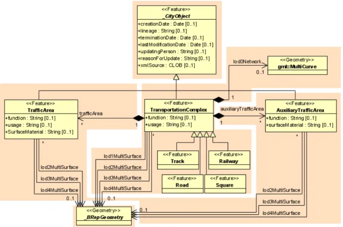
As mentioned before, for setting up Berlin’s database, the modelling of two-dimensional and three-dimensional geometry types is handled in a simplified way. All surface-based geometries are stored as polygons, which are aggregated to MultiSurfaces, CompositeSurfaces, TriangulatedSurfaces, Solids, MultiSolids, as well as CompositeSolids accordingly. This simplification substitutes the more complex representation used for those GML geometry classes in grey blocks in Figure 2. Mapping the UML diagram to the relational schema now requires only one table (SURFACE_GEOMETRY), which is explained in chapter 2.3.2.2
For the representation of textured surfaces, the Appearance model is used. You will find detailed information in chapter 2.2.1.2.
Figure 2: Geometrical-topographical model
For simplification the geometry classes in the grey block are substituded by the construct in the orange block
In order to implement topology, CityGML uses the XML concept of XLinks provided by GML. Each geometry object that should be shared by different geometric aggregates or different thematic features is assigned a unique identifier, which may be referenced by a GML geometry property using a href attribute. The XLink topology is simple and flexible and nearly as powerful as the explicit GML3 topology model. However, a disadvantage of the XLink topology is that navigation between topologically connected objects can only be performed in one direction (from an aggregate to its components), not (immediately) bidirectional, as it is the case for GML’s built-in topology.
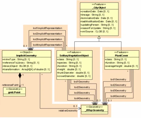
2.2.1.1.2 Implicit Geometry
The concept of implicit geometries is an enhancement of the GML3 geometry model.
An implicit geometry is a geometric object, where the shape is stored only once as a prototypical geometry, for example a tree or other vegetation objects, a traffic light or traffic sign. This prototypic geometry object is re-used or referenced many times, wherever the corresponding feature occurs in the 3D city model. Each occurrence is represented by a link to the prototypic shape geometry (in a local Cartesian coordinate system), by a transformation matrix that is multiplied with each 3D coordinate of the prototype, and by an anchor point denoting the base point of the object in the world coordinate reference system. The concept of implicit geometries is similar to the well-known concept of primitive instancing used for the representation of scene graphs in the field of computer graphics [Foley et al. 1995].
Implicit geometries may be applied to features from different thematic fields in order to geometrically represent the features within a specific level of detail (LOD). Thus, each extension module may define spatial properties providing implicit geometries for its thematic classes.
The shape of an ImplicitGeometry can be represented in an external file with a proprietary format, e.g. a VRML file, a DXF file, or a 3D Studio MAX file. The reference to the implicit geometry can be specified by an URI pointing to a local or remote file, or even to an appropriate web service. Alternatively, a GML3 geometry object can define the shape. This has the advantage that it can be stored or exchanged inline within the CityGML dataset.
Typically, the shape of the geometry is defined in a local coordinate system where the origin lies within or near to the object’s extent. If the shape is referenced by an URI, also the MIME type of the denoted object has to be specified (e.g. “model/vrml” for VRML models or
“model/x3d+xml” for X3D models).
The implicit representation of 3D object geometry has some advantages compared to the explicit modelling, which represents the objects using absolute world coordinates. It is more space-efficient, and thus more extensive scenes can be stored or handled by a system. The visualisation is accelerated since 3D graphics hardware supports the scene graph concept.
Furthermore, the usage of different shape versions of objects is facilitated, e.g. different seasons, since only the library objects have to be exchanged.
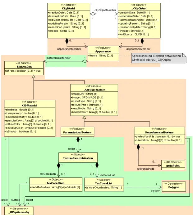
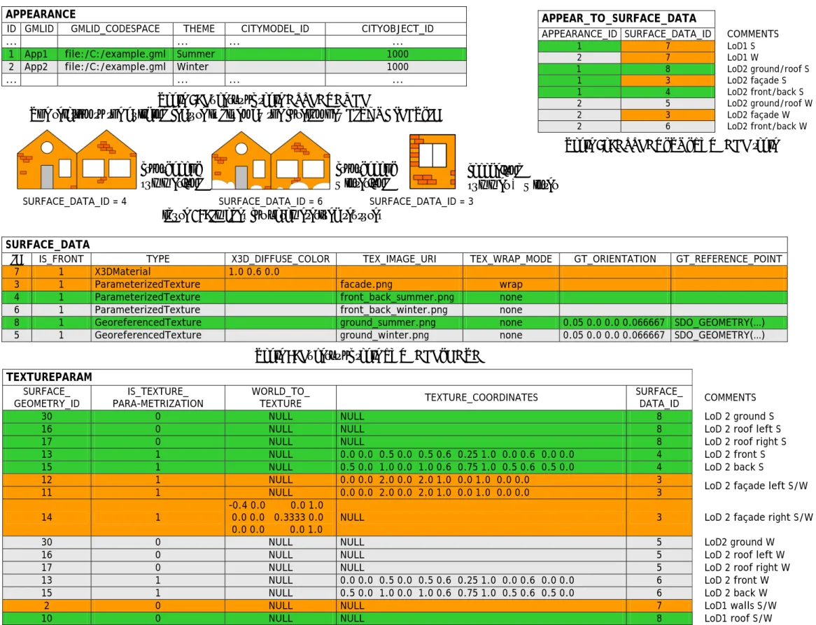
2.2.1.2 Appearance Model
Information about a surface’s appearance, i.e. observable properties of the surface, is considered an integral part of virtual 3D city models in addition to semantics and geometry.
Appearance relates to any surface-based theme, e.g. infrared radiation or noise pollution, not just visual properties and can be represented by – among others – textures and georeferenced textures. Appearances are supported for an arbitrary number of themes per city model. Each LoD of a feature can have individual appearances. Each city object or city model respectively may store its own appearance data. Therefore, the base classes _CityObject and CityModel contain a relation appearanceMember.
Figure 3: Appearance model
Themes are represented by an identifier only. The appearance of a city model for a given theme is defined by a set of objects of class Appearance, referencing this theme through the attribute theme. All appearance objects belonging to the same theme compose a virtual group.
An Appearance object collects surface data relevant for a specific theme through the relation surfaceDataMember. Surface data is represented by objects of the abstract class _SurfaceData. Its only attribute is the Boolean flag isFront, which determines the side (front and back face of the surface) a surface data object applies to.
A constant surface property is modelled as material. A surface property, which depends on the location within the surface, is modelled as texture. Each surface object can have both a material and a texture per theme and side. This allows for providing both a constant approximation and a complex measurement of a surface’s property simultaneously. If a surface object is to receive multiple textures or materials, each texture or material requires a separate theme. The mixing of themes or their usage is not explicitly defined but left to the application.
Materials define light reflection properties being constant for a whole surface object. The definition of the class X3DMaterial is adopted from the X3D and COLLADA specification (cf. X3D, COLLADA specification):
diffuseColor defines the colour of diffusely reflected light.
specularColor defines the colour of a directed reflection.
emissiveColor is the colour of light generated by the surface.
All colours use RGB values with red, green, and blue chanels, each defined as value between 0 and 1. Transparency is stored separately using the transparency element where 0 stands for fully opaque and 1 for fully transparent. ambientIntensity specifies the minimum percentage of diffuseColor that is visible regardless of light sources. shininess controls the sharpness of the specular highlight. 0 produces a soft glow while 1 results in a sharp highlight. isSmooth gives a hint for normal interpolation. If this Boolean flag is set to true, vertex normals should be used for shading (Gouraud shading). Otherwise, normals should be constant for a surface patch (flat shading). Target surfaces of the type _BRepGeometry are linked using the target relation.
The base class for textures is _AbstractTexture. Here, textures are always raster-based 2D textures. The raster image is specified by imageURI using a URI and may contain an arbitrary image data resource, even a preformatted request for a web service. The image data format can be defined using standard MIME types in the mimeType element. Textures can be qualified by the attribute textureType, differentiating between textures, which are specific for a certain object (specific) and prototypic textures being typical for that object surface (typical). Textures may also be classified as unknown. The specification of texture wrapping is adopted from the COLLADA standard. Possible values of the attribute wrapMode are none, wrap, mirror, clamp and border.
_AbstractTexture is further specialised according to the texture parameterisation, i.e. the mapping function from a location on the surface to a location in the texture image. Texture parameterisation uses the notion of texture space, where the texture image always occupies of the region [0,1]² regardless of the actual image size or aspect ratio. The lower left image corner is located at the origin. To receive textures, the mapping function must be known for each surface object.
The class GeoreferencedTexture describes a texture that uses a planimetric projection. Such a texture has a unique mapping function which is usually provided with the image file (e.g.
georeferenced TIFF) or as a separate ESRI world file. The search order for an external georeference is determined by the Boolean flag preferWorldFile. Alternatively, inline specification of a georeference similar to a world file is possible. This internal georeference specification always takes precedence over any external georeference. referencePoint defines the location of the centre of the upper left image pixel in world space and corresponds to values 5 and 6 in an ESRI world file. Since GeoreferencedTexture uses a planimetric projection, referencePoint is two-dimensional and the orientation defines the rotation and scaling of the image in form of a 2x2 matrix (a list of 4 doubles in row-major order corresponding to values 1, 3, 2, and 4 in an ESRI world file). The CRS of this transformation is identical to the referencePoint’s CRS. If neither an internal nor an external georeference is given, the GeoreferencedTexture is invalid. Each target surface object is specified by a target relation. All target surface objects share the mapping function defined by the georeference.
The class ParameterizedTexture describes a texture with a target-dependent mapping function. The mapping is defined by associated classes of _TextureParameterization:
TexCoordList for the concept of texture coordinates, defining an explicit mapping of a surface’s boundary points to points in texture space, and
TexCoordGen when using a common 3x4 transformation matrix from world space to texture space, specified by the attribute worldToTexture.
The related surface objects are linked by the relations polygon and surface respectively.
2.2.1.3 Thematic model
The thematic model consists of the class definitions for the most important types of objects within virtual 3D city models. Most thematic classes are (transitively) derived from the basic classes Feature and FeatureCollection, the basic notions defined in ISO 19109 and GML3 for the representation of spatial objects and their aggregations. Features contain spatial as well as non-spatial attributes, which are mapped to GML3 feature properties with corresponding data types. Geometric properties are represented as associations to the geometry classes described in chapter 2.2.1.1. The thematic model also comprises different types of interrelationships between Feature classes like aggregations, generalizations, and associations.
The aim of the explicit modelling is to reach a high degree of semantic interoperability between different applications. By specifying the thematic concepts and their semantics along with their mapping to UML and GML3, different applications can rely on a well-defined set of Feature types, attributes, and data types with a standardised meaning or interpretation. In order to allow also for the exchange of objects and/or attributes that are not explicitly modelled in CityGML, the concepts of GenericCityObjects and GenericAttributes have been introduced.
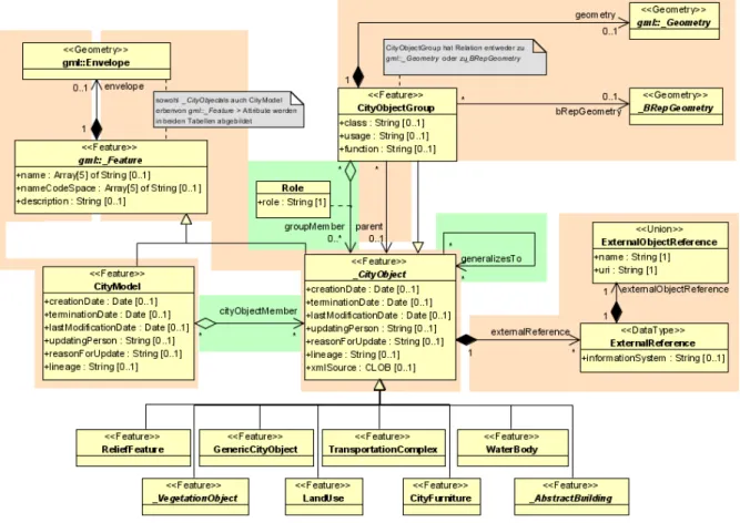
2.2.1.3.1 Core Model
The base class of all thematic classes within CityGML’s data model is the abstract class _CityObject. _CityObject provides a creation and a termination date for the management of histories of features as well as generic attributes and external references to corresponding objects in other data sets. _CityObject is a subclass of the GML class Feature, thus it may inherit multiple names from Feature, which may be optionally qualified by a codeSpace. This enables the differentiation between, for example, an official name from a popular name or names in different languages (c.f. the name property of GML objects, Cox et al., 2004). The generalisation property generalizesTo of _CityObject may be used to relate features, which represent the same real-world object in different LoD, i.e. a feature and its generalized counterpart(s). The direction of this relation is from the feature to the corresponding generalised feature.
Features of _CityObject and its specialized subclasses may be aggregated to a CityModel, which is a feature collection with optional metadata. Generally, each feature has the attributes class, function, and usage, unless it is stated otherwise. The class attribute describes the classification of the objects, e.g. road, track, railway, or square. The attribute function contains the purpose of the object, like national highway or county road, while the attribute usage defines whether an object is e.g. navigable or usable for pedestrians. Here, all three attribute types are stored in String elements. Since the attributes usage and function may be used multiple times, storing them in only one String requires a single white space as unique separator. Furthermore, for each feature the geographical extent can be defined using the Envelope element. Minimum and maximum coordinate values have to be assigned to opposite corners of the feature’s bounding box.
The subclasses of _CityObject comprise the different thematic fields of a city model, in the following covered by separate thematic models: building model (_AbstractBuilding), city furniture model (CiyFurniture), digital terrain model (ReliefFeature), land use model (LandUse), transportation model (TransportationComplex), vegetation model (_VegetationObject), water bodies model (WaterBody) and generic city object model (GenericCityObject). The latter one allows for the modelling of features, which are not explicitly covered by one of the other models. The separation into these models strongly correlates with CityGML’s extension modules, each defining a respective part of a virtual 3D city model.
Figure 4: Core Model and thematic top level classes
3D objects are often derived from or have relations to objects in other databases or data sets.
For example, a 3D building model may have been constructed from a two-dimensional footprint in a cadastre data set. The reference of a 3D object to its corresponding object in an external data set is essential, if an update must be propagated or if additional data is required (like the name and address of a building’s owner in a cadastral information system). In order to supply such information, each _CityObject may have External References to corresponding objects in external data sets. Such a reference denotes the external information system and the unique identifier of the object in this system.
CityObjectGroups aggregate CityObjects and furthermore are defined as special CityObjects.
This implies that a group may become a member of another group realizing a recursive aggregation schema. Since CityObjectGroup is a feature, it has the optional attributes class, function and usage. The class attribute allows a group classification with respect to the stated function and may occur only once. The function attribute is intended to express the main purpose of a group, possibly to which thematic area it belongs (e.g. site, building, transportation, architecture, unknown etc.). The attribute usage can be used, if the object’s usage differs from its function.
Each member of a group may be qualified by a role name, reflecting the role each CityObject plays in the context of the group. Furthermore, a CityObjectGroup can optionally be assigned an arbitrary geometry object. This may be used to represent a generalised geometry generated from the member’s geometries. The parent association linking a CityObjectGroup to a CityObject allows for the modelling of a generic hierarchical grouping concept. This concept is used, for example, to represent storeys in buildings. See figure 4 for the simplified UML diagram.
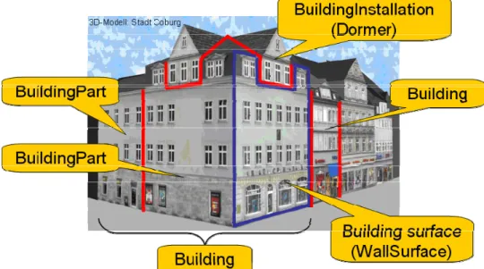
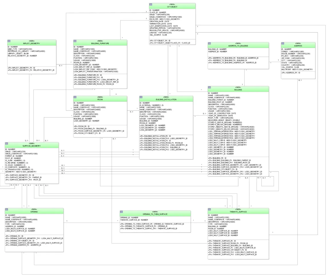
2.2.1.3.2 Building model
Buildings can be represented in four levels of detail (LoD1 to LoD4). The building model (cf.
figure 5) allows the representation of simple buildings that consist of only one component, as well as the representation of complex relations between parts of a building, e.g. a building consisting of three parts – a main house, a garage and an extension. The parts can again consist of parts etc. The subclasses Building and BuildingPart of AbstractBuilding enable these modelling options. In the case of a simple, one-piece house there is only one Building which inherits all attributes and relations from AbstractBuilding. However, such a Building can also comprise BuildingParts which likewise inherit all properties from AbstractBuilding:
the building’s class, function (e.g. residential, public, or industry), usage, year of construction, year of demolition, roof type, measured height, and the number and individual heights of all its storeys above and below ground (cf. figure 6). Furthermore, Addresses can be assigned to Buildings or BuildingParts. In particular, BuildingParts may again comprise BuildingParts as components, because the composition relation is inherited. This way a tree-like hierarchy can be created whose root object is a Building and whose non-root nodes are BuildingParts. The attribute values are generally filled in the lower hierarchy level, because basically every part can have its own construction year and function. However, the function can also be defined in the root of the hierarchy and therefore span the whole building. The individual BuildingParts within a Building must not penetrate each other and must form a coherent object.
Figure 5: Example of buildings consisting of building parts (from: [Plümer et al., 2005])
Figure 6: UML diagram of building model
The geometry of an AbstractBuilding is realized via a relation to the class GM_Composite.
An individual geometry representation is provided for each of the four levels of detail, LoD1 to LoD4. This is realized via the relations lod1Geometry,..., lod4Geometry. Therefore, a single building can have multiple spatial representations in different levels of detail at the same time.
In LoD1, a building model consists of a geometric representation of the building volume.
Optionally, a MultiCurve representing the TerrainIntersectionCurve can be specified. This geometric representation is refined in LoD2 by additional MultiSurface and MultiCurve geometries, used for modelling architectural details like a roof overhang, columns, or antennas. In LoD2 and higher LoDs the outer facade of a building can also be differentiated semantically by the classes _BoundarySurface and BuildingInstallation. A _BoundarySurface is a part of the building’s exterior shell with a special function like wall (WallSurface), roof (RoofSurface), ground plate (GroundSurface), or closing surface (ClosureSurface) as shown in figure 7. Closure surfaces can be used to virtually seal open buildings as for example hangars, allowing e.g. volume calculation. The BuildingInstallation class is used for building elements like balconies, chimneys, dormers, or outer stairs, strongly affecting the outer appearance of a building. A BuildingInstallation is used for the representation of chimneys, stairs, balconies etc. and optionally has the attributes class, function, and usage.
Figure 7: Boundary surfaces (from: [Gröger et al., 2008])
In LoD3, the openings in _BoundarySurface objects (doors and windows) can be represented as thematic objects. In LoD4, the highest level of resolution, also the interior of a building, composed of several rooms, is represented in the building model by the class Room. The aggregation of rooms according to arbitrary, user-defined criteria (e.g. for defining the rooms corresponding to a certain storey) is achieved by employing the general grouping concept provided by CityGML. Interior installations of a building, i.e. objects within a building which (in contrast to furniture) cannot be moved, are represented by the class IntBuildingInstallation. If an installation is attached to a specific room (e.g. radiators or lamps), they are associated with the Room class, otherwise (e.g. in case of rafters or pipes) with _AbstractBuilding. A Room may have the attributes class, function, and usage referenced to external code lists. The class attribute allows a classification of rooms with respect to the stated function, e.g. commercial or private rooms, and occurs only once. The function attribute is intended to express the main purpose of the room, e.g. living room, kitchen. The attribute usage can be used if the object’s usage differs from its function. Since the attributes usage and function may be used multiple times, storing them in only one String requires a single white space as unique separator.
The visible surface of a room is represented geometrically as a Solid or MultiSurface.
Semantically, the surface can be structured into specialised _BoundarySurfaces, representing floor (FloorSurface), ceiling (CeilingSurface), and interior walls (InteriorWallSurface) (cf.
figure 7). Room furniture, like tables and chairs, can be represented in the CityGML building model with the class BuildingFurniture. A BuildingFurniture may have the attributes class, function, and usage.
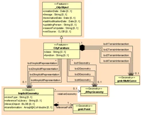
2.2.1.3.3 CityFurniture Model
City furniture objects are immovable objects like lanterns, traffic lights, traffic signs, flower buckets, advertising columns, benches, delimitation stakes, or bus stops. The class CityFurniture may have the attributes class and function (cf. UML-diagram, figure 8). Their possible values are explained in detail in the CityGML specification. The class attribute allows an object classification like traffic light, traffic sign, delimitation stake, or garbage can, and can occur only once. The function attribute describes to which thematic area the city furniture object belongs (e.g. transportation, traffic regulation, architecture etc.), and can occur multiple times. The hierarchy between class and function is not reflected in the external code lists. Inconsistencies have to be checked by the application tools.
Figure 8: City furniture model
Since CityFurniture is a subclass of CityObject and hence is a feature, it inherits the attribute gml:name. As with any CityObject, CityFurniture objects may be assigned ExternalReferences and GenericAttributes. For ExternalReferences city furniture objects can have links to external thematic databases. Thereby, semantical information of the objects, which can not be modelled in CityGML, can be transmitted and used in the 3D city model for further processing, for example information from systems of power lines or pipelines, traffic sign cadastre, or water resources for disaster management.
City furniture objects can be represented in city models with their specific geometry, but in most cases the same kind of object has an identical geometry. The geometry of CityFurniture objects in LoD 1-4 may be represented by an explicit geometry (lodXGeometry where X is between 1 and 4) or an ImplicitGeometry object (lodXImplicitRepresentation with X between 1 and 4). In the concept of ImplicitGeometry the geometry of a prototype city furniture object
is stored only once in a local coordinate system and referenced by a number of features.
Spatial information of city furniture objects can be taken from city maps or from public and private external information systems. In order to specify the exact intersection of the DTM with the 3D geometry of a city furniture object, the latter can have a TerrainIntersectionCurve (TIC) for each LoD. This allows for ensuring a smooth transition between the DTM and the city furniture object.
2.2.1.3.4 Digital terrain model
The city model includes a very adaptable digital terrain model (DTM) which permits the combination of heterogeneous DTM types (grid, TIN, break lines, mass points) available in different levels of detail. Compared to the previous 3D database of Berlin the DTM remains untouched.
A DTM fitting to a certain city model is represented by the class ReliefFeature. This is a CityObject having the LoD step that fits the DTM as attribute. A relief consists of several ReliefComponents. Each of these components that are likewise CityObjects also comprises a LoD step. Individual geometrical types of the components are defined by the four subclasses of ReliefComponent: breaklines, triangular networks (TINs), mass points, and grids (Raster).
Geometrically, the corresponding ISO 19107 or GML classes define these types: breaklines by a single MultiCurve, TINs by TriangulatedSurfaces, mass points by MultiPoint, and Raster by RectifiedGridCoverage.
Figure 9: UML diagram representing the digital terrain model