GRAPH-BASED URBAN OBJECT MODEL PROCESSING
Kerstin Falkowski and J ¨urgen Ebert Institute for Software Technology
University of Koblenz-Landau Universit¨atstr. 1, 56070 Koblenz, Germany
{falke|ebert}@uni-koblenz.de
http://www.uni-koblenz-landau.de/koblenz/fb4/institute/IST/AGEbert
KEY WORDS:Urban, Model, Metadata, Data Structures, Algorithms, Processing, Services.
ABSTRACT:
Urban object models are valuable assets that allow reuse in different applications. Besides the need for exchange formats there is also the need for comprehensive, efficiently processable data structures for such models. This paper presents a graph-based schema for integrated models of urban data, that is an adaption of the comprehensive CityGML approach. It defines an explicit graph representation and thus is well-suited to efficient processing algorithms. The paper demonstrates how appropriate light-weight components realizing different kinds of services on models can be used for consistently processing semantics, geometry, topology and/or appearance of graph-based models compliant to that schema. Several examples are given.
1 INTRODUCTION
Urban models are valuable assets that should be constructed once while being used multiple times in different applications. There- fore the exchange of 3d city models between different tools is indispensable. Various XML formats are being used to achieve interoperability between tools. These formats (e.g. CityGML (Groeger et al., 2008)) are able to carry topological, geometric, semantic, and appearance information, but in different forms and to varying extent.
Applications, like tools for the automatic extraction of topo- graphic objects, build on these urban object models and improve, transform, and analyze them in different ways. XML-technology (e.g. XSLT and XQuery) is widely used to support these activ- ities, but this technology is not well-suited for the implementa- tion of the various algorithms on urban objects which come from the areas of algorithmic geometry, computer graphics, and im- age recognition, since the necessities of efficient content-based traversal of all relevant information is only hard to realize in the essentially tree-like structures supplied by XML.
Therefore, a comprehensive, efficiently processable data struc- ture for urban objects is essential. Geographic information sys- tems share this necessity with route guidance systems, where a graph-like internal representation of data is used for the compu- tation of routing information.
In this paper, we present an approach for the efficient storage, analysis, and manipulation of city models using graphs and for the development of application specific components collectively working on an integrated, efficient graph representation of city models. Import/export from/to CityGML is tackled, as well.1 After a short overview of the state of the art in section 1.1, sec- tion 2 shortly introduces the employed graph and component concepts. Section 3 describes the graph-based integrated model schema with all its aspects, and section 4 shows how quite differ- ent kinds of functionalities can be implemented on such a model by independent components. Section 5 concludes the paper.
1The project is funded by the DFG (EB 119/3-1).
1.1 State of the art
There are several XML-based modeling languages for urban ob- jects. TheCity Geography Markup Language (CityGML)2 is a common information model for the representation of 3d urban objects and an official standard of the Open Geospatial Consor- tium (OGC) since August 2008 (Groeger et al., 2008). Besides representing geometry, CityGML can also be used to model topo- logical and semantic properties of 3d city models and to attach appearance information like textures.
Models described using CityGML can be rendered by Ifc- Explorer for CityGML3 from the Institute for Applied Com- puter Science, Forschungszentrum Karlsruhe or theLandXplorer CityGML Viewer4from Autodesk and byAristoteles5from the In- stitute for Cartography and Geoinformation, University of Bonn.
Besides CityGML there are other languages for the representation of 3d urban objects. One common approach is the OGC standard Keyhole Markup Language (KML)6. CityGML uses a subset of the OGC standardGeography Markup Language (GML) (Cox et al., 2001) for geometry representation, KML derived his ge- ometric elements from GML. KML is often combined with the COLLADA7exchange format for 3d assets. Another 3d model- ing language isExtensible 3D (X3D)8, the successor of theVirtual Reality Modeling Language (VRML)standard.
2 BASIC TECHNOLOGIES 2.1 TGraph technology
For the efficient manipulation of urban object models with all their aspects a versatile and powerful basic technology is needed.
In the context of this work TGraph technology is used.
2http://www.citygml.org,http://www.citygmlwiki.org
3http://www.iai.fzk.de/www-extern/index.php?id=1570
4http://www.3dgeo.de/citygml.aspx
5http://www.ikg.uni-bonn.de/aristoteles
6http://www.opengeospatial.org/standards/kml
7http://www.khronos.org/collada
8http://www.web3d.org/x3d
semantics::
SemanticObject
core::CityObject core::CityModel
core::Site
gen::
GenericCityObject
geometry::
ThreeDPoint - x: Double - y: Double - z: Double geometry::
ThreeDFace appearance::
Appearance
bldg::
AbstractBuilding
bldg::
BoundarySurface
bldg::Opening
bldg::
BuildingInstallation
appearance::
Texture
appearance::
Material appearance::
SurfaceData
appearance::
StaticTexture
appearance::
DynamicTexture
appearance::
TextureCoordinates
grp::
CityObjectGroup
bldg::Door
bldg::
Window
bldg::
RoofSurface bldg::
GroundSurface bldg::
WallSurface
geometry::
ThreeDVolume +outerFace 0..1 +innerFace 0..*
+absBuild 0..*
+outBuildInst 0..*
+absBuild 0..*
+lod1Geometry 0..*
+building 0..*
+surface 0..*
+appearance 0..*
+surfaceData 0..*
+incidentFace 4..*
+incidentVolume 0..*
0..*
isAdjacentToFace 0..*
+surface 2..*
+opening0..*
0..*
isAdjacentToPoint 0..*
+genericObject 0..*
+lod1Geometry 0..*
+cityModel 0..*
+appMember 0..*
+cityModel 0..*
+cityObject 0..*
+cityObject 0..*
+appearance 0..*
0..*
generalizes 0..*
+incidentFace 0..*
+incidentVertex 3..*
+cityObjcetGroup 0..*
+geometry 0..1 +cityObjectGroup
0..*
+groupMember 0..*
+cityObjetGroup 0..*
+parentObject 0..1
+staticTexture 0..*
+face 1
+boundarySurface0..*
+lod2geometry 0..1
+dynamicTexture 0..*
+face 0..*
+texture 1
+textureCoordinates 0..*
+material 0..*
+face 0..*
+buildInst 0..*
+lod2geometry 0..*
+opening 0..*
+lod3geometry 0..1
isAdjacentToVolume
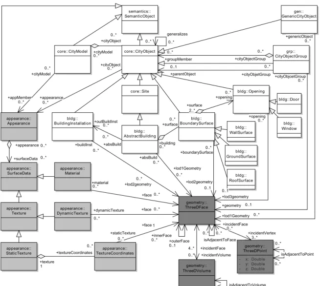
Figure 1: The integrated model schema as a grUML diagram.Semantic entitiesare colored white with namespace ”sem”,appearance entitiesare colored gray with namespace ”app” andgeometry/topology entitiesare colored dark gray with namespace ”geo/top”.
TGraphsare directed graphs whose vertices and edges are typed, ordered and attributed. Their structure, types and attributes help to model the different aspects (topology, geometry, semantics, and appearance annotation) of urban objects in a common in- tegrated data structure. TGraphs are supported by a powerful API (JGraLab9) in combination with a graph query language (GReQL) and a corresponding UML-basedmetamodeling ap- proach (grUML). grUML is a subset of UML class diagrams which allows the specification of classes of TGraphs on the schema level (Ebert et al., 2008). Figure 1 contains an example.
2.2 Lightweight component model
If all relevant data of the urban object model are stored in a TGraph, all processing of the model can be encapsulated in ap- propriate components working on this particular TGraph.
The work described here is based on alight-weight Java compo- nent modelwhich is employed for the different processing activ- ities on the model (see section 4). The component concept is ba- sically an extension of the well-knownstrategy pattern(Gamma et al., 1995). Every component has adefinitionin the form of a Java interface which describes its service and at least oneimple- mentationin the form of a Java class.
9http://jgralab.uni-koblenz.de
Components are serializable and get their data to process asargu- mentsof theirexecute()-methods. Further data that influence their work are handled asparameterswhich have a default value and are manipulated viagettersandsetters. For example some processing steps can be configured by parameters (like thresh- olds).
3 THE INTEGRATED MODEL SCHEMA The internal representation of urban object models by TGraphs has to be specified by a metamodel, calledschemain the follow- ing. This schema defines the set of compliant TGraphs. Classes define the possible vertex types, and associations define the edge types. The attributes of vertices and edges can be added accord- ing to the well-known UML notation, as well. Edge direction is visualized by arrow heads, though it should be noted, that TGraph edges are traversable in both directions by algorithms.
Figure 1 shows the main parts of an integrated schema which de- fines a set of TGraphs for urban objects. (To improve readability all enumeration types and some semantic subclasses as well as attributes are elided.) This schema is inspired by and partially derived from the CityGML 1.0 schema. Especially it follows the idea to separate the four relevant aspects of an urban object model (namely topology, geometry, semantics, and appearance).
Model processing
Model improvement
Incremental model creation Model creation
Model import
Tg model reader CityGML
model reader
Model generation
Example model generation
Initial model generation
Model (view) export
Tg model writer Topological model
improvement
Semantical model improvement
Incremental model supplement
Geometry correction Topology supplementor
Face to plane fitter Face to
rectangle fitter
Semantics supplementor Geometry/topo-
logy supplement
Cuboid completer
Semantic attribute computation
Model transformation
Geometry tansformation
Triangulation Semantics tranfomation
Example building model generator
Initial building model generator
Recognized surface supplementor Automatic
model creation
Geometric model
improvement Dot model
writer
Exclusive or subfeatures
Inclusive or subfeatures Mandatory
subfeature Optional subfeature
CityGML model writer
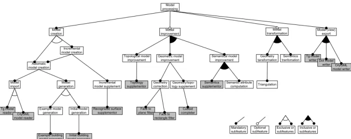
Figure 2: The main components as feature diagram.Component groupsare colored white,concrete componentsare colored gray.
The schema containssemantic entities,appearance entitiesand geometry/topology entities. The semantic part contains enti- ties from the subpackages Core (namespace ”core”), CityOb- jectGroup (namespace ”grp”), Generics (namespace ”gen”) and Building (namespace ”bldg”). It should be noted that in principle also other ontologies might be used for the semantic part.
This grUML schema extends the tree-like XML schema of CityGML to a real graph-based schema, that (meta-)models the entities and relations of urban objects much more explicitly.
In CityGML models multiple occurences of the same object can mostly be modeled by defining the object once and referencing it using XLink10. But this is not possible for every object. As an example, the GML specification offers the definition of the control points of aLinearRing(exterior of aSurface) using the typesDirectPositionorPointProperty. The first is used, if the control points are used only in this geometry element, the second is used used, if the control points may be referenced from other geometry elements. CityGML restricts these possibilities toDirectPosition. This means in CityGML models for every occurence of the same real world point as control point of the surfaces of a building there is a newDirectPosition. And even if XLinks are used, they often can not be processed sequentially and their interpretation is time-consuming.
Using the integrated model schema of figure 1, every entity in an urban object model exists only once as a node and all its uses and occurences are modeled by edges. This explicit, strongly linked representation reduces redundant information and enables automatic model processing by a very large class of algorithms.
It is easy to import and export CityGML models using LODs 1-3 to and from an integrated model.
3.1 Geometry/topology schema part
The geometry/topology part of the integrated model schema dif- fers from the CityGML schema. CityGML uses a subset of GML to represent geometric entities as aboundary representation(Fo- ley et al., 1990, Herring, 2001). But the geometry/topology part of the integrated model schema is not based on this GML subset, since entities and relations are not represented explicitly enough and the same geometric objects may appear more than once in the same model.
10http://www.w3.org/TR/xlink
Here, geometry and topology are modeled as another kind of boundary representation, namely as an extended vertex-edge- face-graph(v-e-f-graph) similar to the well-known and highly efficient Doubly Connected Edge List (DCEL) representation (Muller and Preparata, 1978). A geometric object consists of3d points,3d facesand3d volumes, modeled as typed nodes con- nected via edges. Thegeometric informationis encoded in the attributes of the 3d points, and thetopological informationis rep- resented by theedges between the geometric entities.
3.2 Semantics schema part
The semantics part of the integrated model schema is based on the CityGML modulesCore,CityObjectGroup,GenericsandBuild- ing. Thus, terms like ”building”, ”wall surface” and so forth can be used without further explanation in the following. Each of the mentioned modules is packed in its own subpackage.
3.3 Appearance schema part
The appearance part of the integrated model schema is oriented at the CityGML appearance module. But the different kinds of surface data (material, different kinds of textures) are directly re- lated to the 3d faces they shall be applied to. The model allows static and dynamic textures, but dynamic textures are preferred.
A dynamic texture consists of an image and a transformation ma- trix containing values to compute 2d texture coordinates for ex- isting 3d points concerning the given image. By using dynamic textures, texture coordinates can be updated during model export if their corresponding 3d points have changed during model im- provement.
4 INTEGRATED MODEL PROCESSING The integrated model schema defines the class of TGraphs that represent urban object models with all their aspects. There are a lot of possibleprocessing activitiesfor integrated models, which are introduced in the following. Figure 2 gives an overview over such processing activities and their dependencies in the form of a feature diagram(Czarnecki and Eisenecker, 2000).
Here, the components constitute a product line (Pohl et al., 2005) wherefeatures are implemented byJava components (subsec- tion 2.2). (The components are referenced by identifiers written intypewriterstyle.)
This chapter presents some of these processing components in more detail in order to prove on an example basis that all kinds of processing is possible on integrated models based on TGraphs.
The (intermediate) results of the different processing activities are exported using theCityGMLModelWritercomponent (subsec- tion 4.5) and the XML text is rendered using the IfcExplorer for CityGML (section 1.1). IfcExplorer encodes different (semantic) parts of CityGML models using various colors. Wall surfaces are rendered gray, ground surfaces dark gray, roof surfaces red, doors dark blue, windows light blue and nearly transparent and all other faces cyan. (Unfortunately this distinction is hardly visible in the black-and-white versions of this article.)
4.1 Example
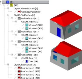
The functionality of the components is demonstrated on the ba- sis of a model of one simple example building, which may be created using theExampleBuildingModelGenerator(subsec- tion 4.2). The full model consists of one ground surface, four wall surfaces, four roof surfaces, one door and five windows, its geometry contains fifteen 3d faces and thirty four 3d points. The user can choose, which model parts should be generated and how they should be connected. Figure 3 shows the full model. Since semantics, geometry and topology of this example model are well known, it is used as example model for most of the components mentioned in the following.
Figure 3: Full example model.
4.2 Model creation.
First of all, an integrated model has to be created. There are two kinds of automatic model creation, namelymodel importand model generation.
Model import. During model import an existing model is read from a file. TgModelReader reads an existing inte- grated model from a .tg-file (the JGraLab file format) and CityGMLModelReaderreads an existing CityGML model from an .xml-file and transforms it into an integrated model. This import respects the CityGML[Appearance,Building,CityObject- Group,Generics]11 profile. Semantic objects from other CityGML modules are ignored at present.
Model generation. During model generation an inte- grated model is created from scratch by a list of cre- ation steps which are hard-coded in Java. The component ExampleBuildingModelGenerator constructs the complete
11The Core module is not mentioned in CityGML profile names, be- cause it belongs to every profile
example model from figure 3 that contains all four integrated model parts. InitialBuildingModelGenerator constructs incomplete models which function as bases for incremental model supplementation activities, which are not explained in further detail here.
4.3 Model improvement
The advantage of a graph-based representation of 3d models be- comes clear if elaborate algorithmic activities are applied to them.
Such activities are especially needed if the imported model is still unprecise and incomplete, for instance because it consists of raw data delivered by some object extraction tool (Falkowski et al., 2009).
Then, the raw models might have to be improved algorithmi- cally. This includestopological,geometricandsemantic model improvement. Geometric model improvement may even be spe- cialized intogeometry correctionandgeometry/topology supple- ment.
Topological model improvement. During topological model improvement different kinds of topological infor- mation are added to an integrated model. The component TopologySupplementor complements an integrated model by adding implicit topological dependencies as explicit arcs in the graph. It may connect all neighboring faces of a 3d face by isAdjacentTo-edges and all neighboring 3d points accordingly to a 3d point, if they are not related yet. Furthermore it may add all 3d faces that lie in another 3d face as inner faces. The component uses the geometric/topologic model part, but changes only topology.
Topological model improvement should always be the first im- provement step, since most of the later processing steps are based on computational geometry algorithms that assume com- plete topological information.
Geometry correction. In raw models, the computed 3d coor- dinates are often only known approximately. This may lead to (slightly) distorted models. See figure 4 as an example.
Figure 4: Geometry correction: Example model with ”wrong” 3d point and therefore with 4 non-planar faces.
During geometry correction the geometry information of an in- tegrated model (i.e. the x-, y- and z-coordinates of 3d points) is corrected. TheFaceToPlaneFitter tests the planarity of all 3d faces and makes them planar, if they are not. TheFaceTo- RectangleFittertests the squareness of all 3d faces and makes
them rectangular, if they are nearly squared. Both components use appropriate approximation algorithms and both use the geo- metric/topologic model part, but change only the geometry. This correction transfers the model of figure 4 to the one in figure 3.
Geometry/topology supplement. Models extracted from 2d images are usually incomplete, since hidden information is miss- ing. For urban data (sometimes) plausible assumptions may be made about the 3d-structure of the objects (e.g. they may be as- sumed to be cuboids).
Figure 5: Geometry/topology supplement: Incomplete Example model (left), supplemented example model (right).
During geometry/topology supplement different kinds of geomet- ric and topological information are added to an integrated model.
TheCuboidCompletertests if there are incomplete cuboids in the integrated model and completes them by adding mirrored in- verted copies of existing 3d faces (figure 5). The component uses the geometric/topologic model part, and enhances geometry as well as topology.
Semantic model improvement. Given a corrected and supple- mented model, also semantic information might be inferable and should be added to the model.
Figure 6: SemanticsSupplement: Model without relations be- tween building and boundary surfaces as well as boundary sur- faces and openings.
During semantic model improvement different kinds of semantic information are added to an integrated model. The component SemanticsSupplementorcomplements an integrated model by adding implicit semantic dependencies as explicit relations. It acts on the assumption, that if an object belongs to an aggre- gation, its parts also have to belong to this aggregation as well
and vice versa. The component adds openings or building to a city model, if their related boundary surfaces belong to this city model. Figure 6 shows a an example of a semantically poor model which is be transformed into the full model of figure 3 by this component. The component uses the semantics and the geometric/topological model part, but changes only semantics.
4.4 Model transformation
A general class of processing activities is the modification of an integrated model by some kind of model transformation. There aregeometry/topology transformationsandsemantic transforma- tions. An example for geometry/topology transformation could betriangulation. An example for latter might be changing the CityGML like semantics partinto one according to a proprietary ontology.
4.5 Model export
In general the integrated model or at least parts of it have to be stored persistently after processing. During model export an in- tegrated model is written to a file.
The componentTgModelWriterwrites a full integrated model to a .tg-file. If the exported .tg-model is imported again, no infor- mation will be lost.
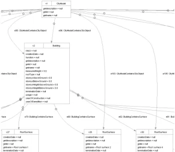
Figure 7: Extraction of the example graph, exported to .dot for- mat and rendered via dotty, a Graphviz tool.
The componentDotModelWriterwrites an integrated model to a .dot-file, the standard file-format of theGraphviz12graph visu- alization software (figure 7). The result can be processed further using Graphviz.
The CityGMLModelWriter writes the integrated model via a special graph traversal algorithm as a CityGML[Appearance,Building,CityObjectGroup,Generics]
model into an .xml-file. The user can influence the result by choosing the LOD and the kinds of textures to be written. The result can be processed further by other tools. For example, it may be rendered via any appropriate CityGML Viewer (see section 1.1). If the exported .xml-model is imported again, information might be lost, since the integrated model contains more information than those covered by CityGML.
12http://www.graphviz.org
4.6 Model analysis
Many more activities might be implemented on the integrated model, since all kinds of queries may be posed on it. Thus, a further processing activity is the analysis of the integrated model.
This activity is not mentioned in the feature diagram in figure 2, since it is carried out as part of nearly every other integrated model processing activity. All tests concerning existing model elements and/or their properties or relationships aremodel anal- ysis steps. There can also betransversal analyses, regardind co- herences of a whole model, a part of a model (e.g. one building) or a special view to a model (e.g. geometry). Using the TGraph structure traversal and analysis of the integrated model is done repeatedly during runtime using the graph API and/or GReQL queries. Transversal analyses are particularly supported by the graph API. For example it offers iterators for all nodes or edges of a special type (and it subtypes) in the whole model.
Listing 1: Building analyser results.
B u i l d i n g 1 I d : 2
Name : Example b u i l d i n g
D e s c r i p t i o n : Example b u i l d i n g model f o r t e s t i n g . Y e a r o f c o n s t r u c t i o n : n o t known
Y e a r o f d e m o l i t i o n : n o t known Number o f a p p e a r a n c e s : 0
Number o f b u i l d i n g i n s t a l l a t i o n s : 0 Number o f b u i l d i n g p a r t s : 0 Number o f b o u n d a r y s u r f a c e s : 9 Number o f w a l l s u r f a c e s : 4 Number o f r o o f s u r f a c e s : 4 Number o f g r o u n d s u r f a c e s : 1 Number o f o p e n i n g s : 6 Number o f d o o r s : 1 Number o f windows : 5 Number o f 3 d f a c e s : 15 Number o f 3 d p o i n t s : 34
L o w e s t 3 d p o i n t : P o i n t 1 : ( 0 . 0 , 0 . 0 , 0 . 0 ) H i g h e s t 3 d p o i n t : P o i n t 9 : ( 2 . 0 , 1 . 0 , 4 . 0 ) H e i g h t : 4
Width : 4 D e p t h : 5 Volume : 68
To demonstrate the usage of querying with GReQL an additional componentBuildingAnalyserwas developed, that writes in- formation about all buildings of the integrated model into a .txt- file. The file contains different kinds of information. At first there issemantic attribute informationlike name, description and year of construction/demolition of the building. Moreover there isse- mantic entity informationlike the number of wall, ground and roof surfaces, the number of doors and windows, and so on. Fur- thermore there aregeometric informationlike the count of points and faces of the building geometry or the lowest and highest point of a building. And there isinferred semantic informationcom- puted using semantic background knowledge in combination with geometry information, like the building height, the building vol- ume, and so forth (listing 1).
5 CONCLUSIONS AND FUTURE WORK This paper showed how geometric, topological, semantic and ap- pearance information can be integrated in one integrated graph model. The class of models was defined by anintegrated model schema. Graph representation gives rise to all kinds of algorith- mic processing, some examples of which were given, including model creation, improvement, transformation, analysis and ex- port. Using alightweight Java component modelsome example
components were implemented and illustrated based on a simple example.
Though the example has toy character, it should suffice to demon- strate the wide range of manipulation possibilities given by an internal integrated graph representation for the enhancement of urban object models. Since TGraph technology is easily applica- ble to graphs containing millions of elements, the approach scales to a wide range of applications.
The integrated model was developed in the context of a project for object-recognition (Falkowski et al., 2009). It forms the basis for the application of efficient graph-matching algorithms in this context.
The integrated model schema is still under construction. But it is easily modifiable and each of the three parts can be replaced by different variants. Further goals are the enhancement of the schema for the fullCityGML base profile(CityGML[full]) and the support for other urban object description languages, likeKM- L/COLLADA(section 1.1). Here the tasks are the change and en- largement of the integrated model schema and the adaption of all existing processing components. Some of the described activi- ties could be splitted to more processing steps. A lot of them can be composed to interesting combined processing activities. And there could even be interactive processing components.
Further research topics could be the supplement of more com- plex model parts to an existing integrated model or the integra- tion of two different integrated models. Another interesting field is the inference of semantics from geometric, topological and/or appearance information.
ACKNOWLEDGEMENTS
This work has been carried out in close cooperation with Peter Decker, Dietrich Paulus and Stefan Wirtz from the Work Group Active Vision as well as Lutz Priese and Frank Schmitt and from the Laboratory Image Recognition, both at the University of Koblenz-Landau.
REFERENCES
Cox, S., Daisey, P., Lake, R., Portele, C. and Whiteside, A., 2001.
OpenGIS Geography Markup Language (GML) Implementation Speci- fication. Technical Report 3.1.1, Open Geospatial Consortium, Inc.
Czarnecki, K. and Eisenecker, U. W., 2000. Generative Programming:
Methods, Tools and Applications. ACM Press/Addison-Wesley Publish- ing Co., New York, NY, USA.
Ebert, J., Riediger, V. and Winter, A., 2008. Graph Technology in Re- verse Engineering, The TGraph Approach. In: R. Gimnich, U. Kaiser, J. Quante and A. Winter (eds), 10th Workshop Software Reengineer- ing (WSR 2008), GI Lecture Notes in Informatics, Vol. 126, GI, Bonn, pp. 67–81.
Falkowski, K., Ebert, J., Decker, P., Wirtz, S. and Paulus, D., 2009. Semi- automatic generation of full CityGML models from images. In: Geoin- formatik 2009, ifgiPrints, Vol. 35, Institut f¨ur Geoinformatik Westf¨alische Wilhelms-Universit¨at M¨unster, Osnabr¨uck, Germany, pp. 101–110.
Foley, J. D., van Dam, A., Feiner, S. K. and Hughes, J. F., 1990. Computer Graphics. Principles and Practice. Addison Wesley.
Gamma, E., Helm, R., Johnson, R. and Vlissides, J., 1995. Design Pat- terns: Elements of Reusable Object-Oriented Software. Addison-Wesley Longman Publishing Co., Inc., Boston, MA, USA.
Groeger, G., Kolbe, T. H., Czerwinski, A. and Nagel, C., 2008. OpenGIS City Geography Markup Language (CityGML) Encoding Standard. Tech- nical Report 1.0.0, Open Geospatial Consortium Inc.
Herring, J., 2001. Topic 1: Feature Geometry (ISO 19107 Spatial Schema). Technical Report 5.0, Open Geospatial Consortium Inc.
Muller, D. E. and Preparata, F. P., 1978. Finding the Intersection of two Convex Polyhedra. Theor. Comput. Sci. 7, pp. 217–236.
Pohl, K., B¨ockle, G. and van der Linden, F., 2005. Software Product Line Engineering. Springer, Berlin.