Deutsche Geodätische Kommission der Bayerischen Akademie der Wissenschaften
Reihe C Dissertationen Heft Nr. 768
Michael Peter
Crowd-sourced reconstruction of building interiors
München 2016
Verlag der Bayerischen Akademie der Wissenschaften in Kommission beim Verlag C. H. Beck
ISSN 0065-5325 ISBN 978-3-7696-5180-5
Deutsche Geodätische Kommission der Bayerischen Akademie der Wissenschaften
Reihe C Dissertationen Heft Nr. 768
Crowd-sourced reconstruction of building interiors
Von der Fakultät Luft- und Raumfahrttechnik und Geodäsie der Universität Stuttgart
zur Erlangung der Würde eines
Doktors der Ingenieurwissenschaften (Dr.-Ing.) genehmigte Abhandlung
Vorgelegt von
Dipl.-Ing. Michael Peter
aus Alzenau
München 2016
Verlag der Bayerischen Akademie der Wissenschaften in Kommission beim Verlag C. H. Beck
ISSN 0065-5325 ISBN 978-3-7696-5180-5
Adresse der Deutschen Geodätischen Kommission:
Deutsche Geodätische Kommission
Alfons-Goppel-Straße 11 ! D – 80 539 München
Telefon +49 – 89 – 23 031 1113 ! Telefax +49 – 89 – 23 031 - 1283 / - 1100 e-mail hornik@dgfi.badw.de ! http://www.dgk.badw.de
Hauptberichter: Prof. Dr.-Ing. habil. Dieter Fritsch Mitberichter: Prof. Dr. rer. nat. Kurt Rothermel Tag der mündlichen Prüfung: 20.11.2015
Diese Dissertation ist auf dem Server der Deutschen Geodätischen Kommission unter <http://dgk.badw.de/>
sowie auf dem Server der Universität Stuttgart unter <http://elib.uni-stuttgart.de/opus/doku/e-diss.php>
elektronisch publiziert
© 2016 Deutsche Geodätische Kommission, München
Alle Rechte vorbehalten. Ohne Genehmigung der Herausgeber ist es auch nicht gestattet,
die Veröffentlichung oder Teile daraus auf photomechanischem Wege (Photokopie, Mikrokopie) zu vervielfältigen.
ISSN 0065-5325 ISBN 978-3-7696-5180-5
3
Abstract
Location-based services (LBS) have gained huge commercial and scientific interest in recent years, due to the ubiquitous and free availability of maps, global positioning systems, and smartphones. To date, maps and positioning solutions are mostly only available for outdoor use. However, humans spend most of their time indoors, rendering indoor LBS interesting for applications such as location-based advertisement, cus- tomer tracking and customer flow analysis. Neither of the two prerequisites for indoor LBS - a map of the user’s environment and a positioning system - is currently generally available: Most positioning methods currently under scientific investigation are based either on fingerprint maps of electro-magnetic signals (e.g. WiFi) or inertial measurement units. To overcome the flaws of these methods, they are often suppor- ted by models for the human movement which in turn rely on indoor maps. Ready-made maps, on the other hand, are generally unavailable due to indoor mapping being mostly manual, expensive and tedious.
The vast amount of unmapped indoor space therefore calls for the transfer of methods used by Volunteered Geographic Information (VGI) communities like OpenStreetMap to indoor mapping. These methods com- prise the digitization of features of interest such as building outlines from aerial images released to the com- munity and the use of position traces. In this thesis, approaches are illustrated which can serve to enable this transfer.
On the one hand, the thesis shows how photographs of evacuation plans - which are a compulsory part of the safety equipment of publicly used buildings in many countries - can substitute for the aerial images in the indoor domain. Due to the standardised nature of such plans, the manual digitization employed by VGI mappers in the outdoor domain can be replaced by an automatic reverse-engineering pipeline. To this end, the image is pre-processed and symbols, which depict evacuation routes or emergency equipment, are detected. Subsequently, foreground objects (i.e. walls) are distinguished from the background using an adequate binarisation operation. Based on the binary image, the sought-after vector information can be extracted by skeletonisation and skeleton tracing. The model is finalised by a bridging operation of the previously detected symbols which occlude parts of walls or stairs. As the model resulting from these operations is only available in a coordinate system defined by the original image, the transformation to a world-coordinate system or, at least, the unknown scale has to be determined. To this end, the indoor model is matched to an available model of the building’s external shell. By detection of stairs, an approximate floor height can be computed and the 2D model is extruded to a 3D model.
On the other hand, geometric features and semantic annotations may be added to existing models using
pedestrian traces recorded by an indoor positioning system. As suitable generally available and low-cost
systems do not exist yet, their existence is simulated in this work by a dead-reckoning system basing on a
foot-mounted inertial measurement system. Methods for the derivation of the initial position and orienta-
tion necessary for the application of such a system are shown, as well as methods enabling the correction of
remaining errors. The latter comprise an alignment approach using the external building shell and a map-
matching method which employs the existing coarse model derived from the evacuation plan. Building
4
on the collected pedestrian traces, semi-automatic and automatic approaches for the existing models’ se- mantic and geometric refinement are presented which range from semantic annotation using the analysis of photographed doorplates to automatic door reconstruction. Furthermore, a geometric update of single rooms by conjoint analysis of the coarse model, pedestrian traces and a hand-held low-cost range camera is described.
Lastly, works of indoor mapping are presented which are based on pedestrian traces and higher-level know-
ledge about the interior structure of the building modelled in an indoor grammar. Due to the differing char-
acteristics of the two central elements of building interiors, corridors and rooms, the grammar is composed
of a Lindenmayer system modelling the floor’s corridor system and a split grammar describing the room lay-
out which is found in the non-corridor spaces. The grammar is put to the test by applying it to distributedly
collected noisy trace data.
5
Kurzfassung
Das kommerzielle und wissenschaftliche Interesse an ortsbezogenen Diensten (location-based services, LBS) hat in den vergangenen Jahren stark zugenommen, verursacht durch die allgegenwärtige und kos- tenlose Verfügbarkeit von Karten, globalen Positionierungssystemen und die weite Verbreitung von Smart- phones. Gegenwärtig sind Karten und Positionierungslösungen hauptsächlich für die Verwendung im Außen- raum nutzbar. Menschen verbringen jedoch den Großteil ihrer Zeit in Gebäudeinnenräumen, was LBS für Anwendungen wie ortsbezogene Werbung oder Verfolgung und Analyse von Kundenbewegungen interess- ant macht. Jedoch ist keine der beiden Voraussetzungen für LBS - eine Karte der Umgebung des Benutzers und ein System für die Bestimmung seiner Position - derzeit in der Breite verfügbar: Die meisten Posi- tionierungslösungen, die gegenwärtig wissenschaftlich untersucht werden, basieren entweder auf Karten, in welchen die Fingerabdrücke elektromagnetischer Signale (wie WLAN) gespeichert sind, oder auf iner- tialen Messeinheiten. Um die Schwachstellen solcher Systeme auszugleichen, werden diese häufig durch Modelle der menschlichen Bewegung unterstützt, welche ihrerseits Karten des Innenraums benötigen. Zum gegenwärtigen Zeitpunkt fehlen jedoch direkt verwendbare Karten im Allgemeinen, da die Kartierung von Innenräumen meist einen großen manuellen und finanziellen Aufwand erfordert. Die große Menge nicht kartierten Raumes motiviert daher eine Übertragung der Methoden, die von Internetcommunities wie Open- StreetMap eingesetzt werden, welche sich mit der Erfassung von Geodaten durch Freiwillige (Volunteered Geographic Information, VGI) beschäftigen. Diese Methoden bestehen zum Einen aus der Digitalisierung von Karteninhalten wie Gebäudegrundrissen aus Luftbildern, die der Community zur Verfügung gestellt wurden, zum Anderen aus der Verwendung von Benutzerfußspuren. In dieser Arbeit werden Ansätze bes- chrieben, die die Realisierung der Übertragung dieser Methoden unterstützen können.
Zunächst wird vorgestellt, wie Fotografien von Fluchtplänen, welche laut Vorschrift in vielen Ländern Teil
der Sicherheitsausstattung von öffentlich genutzten Gebäuden sind, die im Außenraum genutzten Luftb-
ilder ersetzen können. Aufgrund des standardisierten Aussehens solcher Pläne kann die manuelle Di-
gitalisierung, welche von VGI-Kartographen im Außenraum eingesetzt wird, durch einen automatisierten
Reverse-Engineering-Prozess ersetzt werden. Hierfür wird das Bild einer Vorprozessierung unterworfen
und Symbole, welche Fluchtwege oder Sicherheitsausrüstung darstellen, werden detektiert. In der Folge
können mittels einer geeigneten Binarisierungs-Operation Objekte im Vordergrund (Wände) vom Hinter-
grund unterschieden werden. Auf Basis des Binärbildes wird die gesuchte Vektorinformation mit Hilfe von
Skelettierung und Skelettverfolgung extrahiert. Anschließend wird das Modell durch die Überbrückung der
vorher detektierten Symbole, welche Teile von Wänden oder Treppen überdecken, finalisiert. Da das resulti-
erende Modell in einem Koordinatensystem definiert ist, welches durch das Originalbild vorgegeben wird,
muss die Transformation in ein Weltkoordinatensystem, bzw. als Mindestanforderung der Maßstabsun-
terschied, bestimmt werden. Die Transformation wird durch einen Abgleich des Innenraummodells mit
einem verfügbaren Modell der Gebäudeaußenhülle erhalten. Indem eine genäherte Stockwerkshöhe aus
der Anzahl detektierter Treppenstufen berechnet wird, kann das 2D-Modell zu einem 3D-Modell erweitert
werden.
6
Darüber hinaus kann eine Erweiterung existierender Innernaummodelle durch geometrische und seman- tische Informationen anhand von Benutzerfußspuren, welche mittels eines Innernaumpositionierungssys- tems aufgezeichnet wurden, erfolgen. Da jedoch zum jetzigen Zeitpunkt keine allgemein verfügbaren, pre- iswerten Systeme verfügbar sind, wird ihre Existenz in dieser Arbeit durch ein System simuliert, welches die Koppelnavigation auf Basis einer am Fuß angebrachten Inertialen Messeinheit realisiert. Zunächst werden Ansätze vorgestellt, welche dazu dienen können, die benötigten Startwerte in Bezug auf Orientierung und Position zu bestimmen, sowie Methoden, welche die Korrektur verbleibender Fehler erlauben. Letztere um- fassen einen Ansatz zur Korrektur der Ausrichtung des Benutzerpfads auf Basis der Gebäudeaußenhülle und eine Methode zum Kartenabgleich unter Verwendung des Grobmodells, welches beispielsweise aus dem Fluchtplan abgeleitet wurde. Basierend auf den aufgezeichneten Benutzerfußspuren werden halbautomat- ische und automatische Methoden beschrieben, die eine semantische und geometrische Verfeinerung der vorliegenden Modelle erlauben. Diese reichen von der semantischen Anreicherung anhand der Analyse fotografierter Türschilder bis zur automatischen Türrekonstruktion. Des weiteren wird die Aktualisierung einzelner Raumgeometrien auf Basis einer gemeinsamen Analyse des Grobmodells, der Benutzerfußspuren und einer handgeführten low-cost Tiefenkamera wird darüber hinaus beschrieben.
Abschließend werden Arbeiten vorgestellt, welche die Innenraumkartierung unter Verwendung von Ben-
utzerfußspuren und in einer Innenraumgrammatik gespeichertem höherwertigem Wissen über die Struk-
tur des Gebäudeinnenraums erlauben. Aufgrund der unterschiedlichen Eigenschaften der beiden zentralen
Elemente von Gebäudeinnenräumen setzt sich diese Grammatik aus einem Lindenmayer-System, welches
das Korridorsystem des Stockwerks modelliert, und einer Split-Grammatik, die die Anordnung der Räume
in den anderen Bereichen beschreibt, zusammen. Die Tests dieser Grammatik, welche mittels fehlerbe-
hafteter, verteilt erfasster Benutzerfußspuren durchgeführt wurden, werden darüber hinaus dargestellt.
7
Contents
1 Introduction 11
1.1 Motivation . . . . 11
1.2 Objectives . . . . 12
1.3 Structure of the thesis . . . . 13
2 Indoor positioning and tracking 15 2.1 Infrastructure-based . . . . 16
2.1.1 Light . . . . 18
2.1.2 Image-based methods . . . . 19
2.1.3 Sound . . . . 21
2.1.4 Electro-magnetic signals . . . . 23
2.1.5 Maps . . . . 29
2.2 Infrastructure-independent . . . . 30
2.2.1 Foot-mounted MEMS IMUs . . . . 31
2.2.2 Smartphone sensor equipment . . . . 33
2.2.3 Aiding methods . . . . 35
3 Mapping the interior structure of buildings 39 3.1 Data models . . . . 40
3.2 Manual and image-based methods . . . . 42
3.2.1 Manual methods . . . . 42
3.2.2 Semi-automatic methods using panoramic images . . . . 43
3.2.3 Automatic monocular methods . . . . 44
3.3 Point cloud and depth map based methods . . . . 45
3.3.1 Acquisition methods . . . . 45
3.3.2 Segmentation and reconstruction methods using point clouds . . . . 53
3.4 Methods using pedestrian traces . . . . 57
4 Reconstruction of indoor environments by reverse-engineering of existing maps 61 4.1 Related approaches . . . . 61
4.2 Evacuation plans . . . . 64
4.3 Overview . . . . 66
4.4 Image pre-processing . . . . 67
4.4.1 Image rectification and detection of the detailed plan . . . . 67
4.4.2 Background normalisation . . . . 68
4.4.3 White background reconstruction and colour correction . . . . 69
8 Contents
4.5 Geo-referencing and scaling . . . . 70
4.5.1 Preparation of the contours . . . . 71
4.5.2 Cartographic generalisation . . . . 72
4.5.3 Contour matching . . . . 73
4.6 Symbol detection . . . . 74
4.6.1 Symbol detection using contour detection and template matching . . . . 74
4.6.2 Symbol detection using colour segmentation . . . . 75
4.7 Binarisation . . . . 76
4.8 Symbol bridging and 2D modelling . . . . 77
4.9 Stair detection and 3D modeling . . . . 78
5 Reconstruction by use of pedestrian traces 81 5.1 Indoor positioning using a foot-mounted MEMS IMU . . . . 82
5.2 Positioning support methods . . . . 83
5.2.1 Deriving initial values from photographed evacuation plans . . . . 83
5.2.2 Alignment . . . . 84
5.2.3 Height correction using stair and elevator detection . . . . 85
5.2.4 Map-matching . . . . 87
5.3 Semantic model improvement . . . . 89
5.3.1 User interaction . . . . 90
5.3.2 OCR analysis of photographed door plates . . . . 90
5.4 Geometric model refinement . . . . 91
5.4.1 User interaction . . . . 92
5.4.2 Automatic door reconstruction . . . . 92
5.4.3 Model refinement using a low-cost range camera . . . . 92
5.5 Trace-based reconstruction supported by an indoor grammar . . . . 95
5.5.1 Grammar definition . . . . 96
5.5.2 Trace analysis . . . . 97
5.5.3 Grammar-based completion and reconstruction . . . . 98
6 Results and discussion 101 6.1 Evaluation of reverse engineered plans . . . 101
6.1.1 Resolution . . . 101
6.1.2 Accuracy of the geo-reference . . . 102
6.1.3 Evaluation of the resulting model’s precision . . . 103
6.1.4 Height . . . 108
6.2 Accuracy evaluation of the refinement from pedestrian traces . . . 108
6.2.1 Precision of traces resulting from the positioning system . . . 108
6.2.2 Overall accuracy of the positioning method and the model refining features . . . 108
6.2.3 Accuracy of the geometric refinement using a low-cost range camera . . . 109
6.3 Quality of the grammar-supported reconstruction . . . 110
7 Conclusions and future work 113
List of Figures 115
Contents 9
List of Tables 119
Bibliography 119
Appendix A: Affine and perspective transformation parameters estimation 137
Appendix B: Foot-mounted MEMS IMU positioning 141
Acknowledgements 143
Curriculum Vitae 145
10
11
1 Introduction
1.1 Motivation
Location based services (LBS) such as pedestrian navigation rely on two central components - a model of the user’s local environment and a positioning device. During the past decade LBS have attracted huge interest and been tapped for both commercial and private applications. This interest has been fuelled by a) the ubiquitous availability of low-cost positioning systems based on Global Navigation Systems (GNSS) like GPS, GLONASS, and the upcoming BeiDou and GALILEO, and b) freely and globally available maps from major suppliers like Google, Microsoft, Nokia and Apple or the OpenStreetMap community.
All the commercial map providers are interested in keeping their maps up to date in order to attract com- mercial customers interested in advertising as well as private customers whom the advertisements are aimed at. OpenStreetMap, on the other hand, being a community-driven alternative, can rely on a loyal and active mapper base ensuring its up-to-dateness. To this end, the voluntary mappers utilize manually annotated GNSS traces as well as aerial images released to the community by their owners (e.g. Bing Maps and Yahoo Maps).
Thus, with positioning and up-to-date maps being available, outdoor LBS seem to be a solved problem.
However, people spend more than 90% of their time in building interiors like their home, offices or shopping malls (EPA, 1989). Consequently, this induces increased interest in the possibility to extend LBS to these currently unmapped spaces. However, neither of the two requirements for indoor LBS are fulfilled to date.
The map providers mentioned above have started to map spacious and highly frequented indoor areas such as malls and airports, either by employing manual efforts or involving the building owners 1 . The problem of a lack of indoor maps, in principle, could be left to commercial map providers who are interested in making profit of indoor LBS. Public buildings like administrative offices, however, while being of public interest in terms of e.g. routing, do not provide profit to those map providers. Automatic mapping of building interiors is still a major problem: while as-planned data mostly is available (in the form of CAD plans or the like), indoor environments are often subject to rearrangements. The registration of different data sets covering parts of the indoor environment is problematic as is the geo-referencing respectively the registration to the external building shell. These problems could be overcome using an available indoor positioning system.
A very promising solution for the indoor mapping problem seems to be the transfer of community-driven approaches in order to enable crowd mapping of the vast unmapped indoor spaces. Analogous to the out- door OpenStreetMap mapping methods, such a crowd-sourced indoor mapping method needs base data like images and traces collected using a positioning system.
1
like in Google’s approach: https://www.google.com/maps/about/partners/indoormaps/ (last visited 2nd February
2016)
12 1 Introduction Furthermore, the positioning problem is only partially solved to date, despite the highly increased interest visible in the scientific community in the recent years. Various methods have been presented, however, the most promising seem to be found in electro-magnetic signals such as Wi-Fi, the analysis of inertial measurements or combinations of both 2 . To bound the errors of these positioning approaches, mobility models based on the environment model have been proven very effective. Thus, the positioning and map- ping problems are interconnected: mapping would profit from an available indoor positioning system in the registration of different data sets, while most upcoming or available positioning systems rely on an en- vironment model in order to deliver the highest accuracy possible.
In order to overcome the lack of digital models of building interiors, this thesis investigates methods en- abling or facilitating crowd-sourced indoor mapping. To this end, it is shown that the aerial images used by Volunteered Geographic Information (VGI) communities like OpenStreetMap can be replaced by pho- tographed evacuation plans. Evacuation plans are a compulsory part of all public buildings’ emergency equipment in many countries. They may be used in a manual modelling strategy analogous to the Open- StreetMap method in the outdoor domain. However, as will be shown, they can also be analysed automat- ically due to their standardised features. The GNSS position traces which form the base of outdoor VGI mapping can be replaced by indoor traces collected using a foot-mounted inertial sensor. These indoor traces can serve in the geometric and semantic refinement of existing models, or be analysed using a gram- mar which contains rules for the architectural style of the building’s interior structure.
1.2 Objectives
The aim of this thesis is the feasibility study of a system for the crowd-sourced acquisition of building in- teriors. To this end, the system bases on the two aforementioned types of data, represented here by images of evacuation plans and indoor position traces.
Objective 1: Make evacuation plans usable for indoor mapping, navigation and positioning support.
On the one hand, this can be done by geo-referencing the image in order to display pedestrian traces and support human way-finding. On the other hand, the main objective is the derivation of explicit polygonal models which can be used for routing purposes and be applied in the context of positioning support meth- ods like map-matching. In contrast to the aerial images used in the manual outdoor OpenStreetMap map- ping strategy, the images depict pre-processed model information about the building interior’s layout, ren- dering an automated analysis possible. The difficulties which have to be overcome in order to reach this goal are the following: 1) there is no measurement redundancy. All the information for the derivation of the model must be extracted from the photographed evacuation plan. 2) In contrast to existing approaches which are based on scanned paper plans, the photographs suffer from a low resolution and flaws resulting from the lighting and image capturing conditions. Lastly, 3) geo-referencing and scaling should be derived automatically.
Objective 2: Develop methods for the refinement of coarse models (as e.g. stemming from the automated analysis of photographed evacuation plans) by use of pedestrian traces.
2
apart from commercial systems basing on Bluetooth low energy beacons introduced recently
1 Introduction 13 Low-cost indoor positioning systems with the needed accuracy are not available yet. However, as will be shown, expensive sensor equipment like foot-mounted inertial measurement units together with suitable signal processing methods can be used as a preview, having the sought-after characteristics like infrastructure- independence and high accuracy. As such systems deliver coordinates relative to a pre-defined initial ori- entation and position, these values shall be obtained e.g. by analysis of the photographed evacuation plan.
The position traces, additionally improved by use of an available model of the building’s external shell and the coarse model, open the possibility to refine and update the coarse model in various ways. As will be shown, semantic information can be added manually at the user’s current position, but also by analysing the content of photographed doorplates. Furthermore, the model can be refined geometrically by the auto- matic detection of door openings in a conjoint analysis of model and user trace, as well as by processing point clouds collected using a low-cost range camera.
Objective 3: Reconstruct the indoor space using pedestrian traces and an indoor grammar.
Using knowledge about the indoor structure’s layout modelled in a rule system - i.e. grammar - enables the reconstruction of full floorplans based solely on pedestrian traces. To this end, the approach is based on a large number of traces collected distributedly by people walking around in the building.
1.3 Structure of the thesis
The thesis is structured as follows: Chapter 2 gives an overview over existing indoor positioning methods, subdivided into infrastructure-based and infrastructure-independent approaches. In chapter 3, the related work in indoor mapping is presented.
According to the first objective described above, chapter 4 is dedicated to an in-depth description of the im- plemented processing pipeline for the reconstruction of building interiors from photographed evacuation plans. Apart from the presentation of steps like the pre-processing of the acquired image, binarisation, symbol detection and bridging, this chapter includes a short review of existing methods for the reverse- engineering of scanned paper plans.
Ojectives two and three are comprised in chapter 5. Thus, this chapter initially describes methods for the geometric update and semantic refinement of the resulting coarse models by means of an indoor position- ing system. The implemented positioning system and methods supporting it are presented. Apart from manual methods, the refinement and update of the coarse model includes the annotation by semantic in- formation using the analysis of photographed door plates and the automatic reconstruction of doors from the combination of the pedestrian trace and the coarse model. Additionally, the geometric refinement us- ing a low-cost range camera as well as the reconstruction solely based on user traces employing an indoor grammar are presented.
Chapter 6 concludes the main part with an evaluation and discussion of the results of all presented recon-
struction methods. Chapter 7 gives the conclusion and a short outlook on future research in these areas.
14
15
2 Indoor positioning and tracking
GNSSs played a major role in the success of location based services (LBS) experienced in the recent years.
While the ubiquitous availability of positioning systems fosters LBS in the outdoor domain, indoor LBS are hindered by the absence of an analogously pervasive technology. However, there is a wide variety of indoor applications which could either benefit or would be rendered possible by the knowledge of a person’s current position 1 .
Applications like “user mobility” or “nomadic computing”, i.e. digital workplaces following their users to the respective nearest computer (Want et al., 1992), lost much of their relevance in times of ubiquitous computing using smartphones and tablets. Some of the concepts, however, still remain interesting, e.g.
data security scenarios such as the ones described by Blankenbach et al. (2007): automatic proximity-based unlocking of computers or the printing of confidential documents which is delayed until the authorized recipient is near the printer.
In emergency cases, the positions of both a person seeking help and the helpers can prevent injuries or fatalities. The former example is governed by directives like “Enhanced 911 (E911)” in the United States and
“Enhanced 112 (E112)” in the EU with the aim of ensuring that an emergency caller’s position is determined and transmitted to the action forces. For example, the US Federal Communications Commission (FCC) claims the horizontal indoor position of an emergency caller to be determinable to within 50 meters in 80%
of cases in the near future (FCC, 2014). Then again, the positions of members of the action forces have to be known in order to coordinate them and guide them in situations with low visibility like smoke-filled areas.
In health care, especially in hospitals, localization and tracking of patients, personnel, and equipment are areas where commercial systems are currently put to use. Similarly, the ageing societies in post-industrial countries motivate research in the area of Assisted Living (Schindhelm and MacWilliams, 2011) where track- ing of a person’s exact position is part of the situation recognition. Furthermore, real-time tracking of players during indoor sports events is of interest (e.g. in basketball 2 ).
Asset management as well as tracking of products, production resources, and personnel inside factories can render production more efficient, as e.g. in the SmartFactory (Zuehlke, 2010). Turning off the lights and heating in rooms which were left empty could save energy and money. Construction and building manage- ment could profit e.g. from augmented reality enhanced inspection of wires and pipes behind walls. This demands a very high accuracy of indoor positioning methods (as well as accurate and complete models).
However, the biggest interest is in commercial location-based services (LBSs), as this market has been grow- ing for years in outdoor areas. These LBS applications include navigation and location-based reminders, as
1
robotic applications and methods are left aside as being out of the scope of this thesis
2
www.sportiq.fi (last visited 2nd February 2016)
16 2 Indoor positioning and tracking well as location check-ins and location-based games such as geo-caching and Google’s Ingress 3 . Apart from these customer-centered applications, benefits for shop owners can be found in location-based advert- isement, customer tracking and customer flow analysis. On the customer side, however, many enhanced applications pose threats to personal privacy.
At the highest level, Methods for the position determination inside a building or enclosed structure can be distinguished by their autonomy from or dependence on existing infrastructure. This distinction defines the structure of this chapter which recapitulates the related work concerning infrastructure-based as well as infrastructure-independent indoor positioning methods.
In contrast to the definition found in Chen et al. (2012), where infrastructure-based methods are defined as relying on hardware actively deployed for the purpose of positioning, infrastructure-based methods here shall comprise all methods in need of external signals, hardware, or information. An overview over related work in this field is given in section 2.1.
The infrastructure-independent methods described in section 2.2, on the other hand, are self-contained.
To this end, they use inertial measurement units as well as other sensors in order to implement pedestrian dead-reckoning. As the errors in dead-reckoning are likely to grow out of bounds quickly, this section fur- thermore outlines some aiding methods which were presented in the related work.
2.1 Infrastructure-based
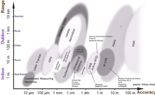
Despite the relatively short period of time in which pedestrian positioning systems for building interiors have been in the focus of the research community, the number and diversity of approaches motivated a quite large number of survey papers. In the area of infrastructure-based systems, these are Hightower and Borriello (2001), Gu et al. (2009), Mautz (2009), Koyuncu and Yang (2010), Deak et al. (2012) and Stojan- ovi´c and Stojanovi´c (2014). Figure 2.1 gives an overview over infrastructure-based positioning methods with their according accuracies as available in literature respectively in the market at the time of writing of the survey paper (Mautz, 2009). It still represents a relatively complete overview apart from some ex- cluded research fields such as approaches based on light, images, or FM radio/TV signals. Furthermore, the recent research concerning geo-magnetism fingerprinting as well as current hardware developments (e.g. bluetooth low energy) is not reflected. Most of the depicted ranges and accuracies are true up to now.
However, newer developments using cell-phone signals (GSM) in the context of received signal strength fingerprinting improved the achievable accuracies to match those of WiFi-based fingerprinting.
3
https://www.ingress.com/ (last visited 2nd February 2016)
2 Indoor positioning and tracking 17
Figure 2.1: Overview of infrastructure-based indoor positioning methods and according accuracies as presented by Mautz (2009)
Apart from their range, accuracy, and the used signals, infrastructure-based indoor positioning methods can be further subdivided according to various characteristics (compare also Hightower and Borriello, 2001):
• tracking vs. ego-motion positioning: in tracking systems the coordinates of the subject to be posi- tioned are computed by systems in the infrastructure. Ego-motion positioning systems, on the other hand, allow their determination by the subject itself, thus offering a higher level of privacy
• the system’s ability to deliver coordinates continuously or only at discrete points
• the system’s ability to deliver metric or symbolic coordinates (e.g. room identifiers)
• method used for the coordinate determination:
– proximity: discrete location updates whenever the system detects proximity to a beacon – angulation (angle-of-arrival, AOA): coordinates are computed by intersecting lines reconstruc-
ted from the different angles in which the signals arrive. Mostly used in tracking systems due to the necessity of rotating antennas or antenna arrays
– lateration: coordinates are computed by intersection of circles/spheres (time-of-arrival, TOA) or hyperboles (time-difference-of-arrival, TDOA) which are reconstructed using the runtimes or runtime differences of the signals, respectively. While TOA needs sender-receiver synchron- ization, TDOA relies on sender synchronization which can be established more easily as only affecting the infrastructure
– fingerprinting: in an offline phase, a map of fingerprints (e.g. consisting of received signal strengths) at known positions is constructed. During the online phase, coordinates are com- puted using feature matching
• necessity of a direct line-of-sight between sender and receiver (line-of-sight vs. NLOS), where the
definition of the line-of-sight is dependent on the used signals
18 2 Indoor positioning and tracking
• costs and scalability
There are various, obvious ways of obtaining a person’s indoor position without intermediate measure- ments. Examples are the push of a button, use of a key card, drawing money at an ATM or paying with a credit card in combination with the knowledge of the according facilities’ positions (Hightower and Borri- ello, 2001).
Another straightforward method for direct pedestrian localization was presented in Orr and Abowd (2000):
the SmartFloor. As the name suggests, it consists of floor tiles measuring the ground reaction force profiles of the pedestrians’ steps. While this enables a direct position determination, the major problem to be solved is the identification and tracking of individual users of the system. The identification is carried out using features of the ground reaction force profiles like mean, standard deviation, total area under the profile curve etc., resulting in an accuracy of 93% independent of differing shoes, while the authors left tracking for future work. Building on direct, tactile measurements, the system does not scale well and the installation costs are high.
Apart from these direct methods, all other infrastructure-based indoor positioning systems are based on contactless measurements. In the remaining subsections of this section, an overview of the wide range of related work is given, covering light-based methods as well as methods using images, sound, and electro- magnetic signals. Electro-magnetic signals can be further subdivided into TV, FM radio, or cell phone sig- nals as well as GPS, RFID, bluetooth, UltraWideBand, magnetism, and WiFi.
2.1.1 Light
There are various ways in which light can be leveraged for the determination of indoor positions. They can be distinguished by the use of visible vs. infrared light as well as their characteristics such as ego-motion vs.
tracking systems using e.g. stereo-vision and their use of dedicated deployed lights vs. fingerprinting of the available ambient light. Obviously, all of these methods need a direct line-of-sight in order to work.
The “Active Badge” system (Want et al., 1992) was one of the earliest efforts to enable user tracking inside of buildings. Its badges transmit a unique code using pulse-width modulated infrared light every 15 seconds for 1/10 of a second. This signal is captured by sensors distributed throughout the building which are polled by a server. In order to reach the goal of room-granular localization infrared signals were chosen because they are blocked by walls. In contrast to triangulating methods signal reflections are welcome in this sys- tem. Aitenbichler and Muhlhauser (2003) similarly use infrared LEDs emitting an identifier code, however, tracking the LEDs by stereo cameras with known intrinsic and extrinsic parameters. This way, they reach an accuracy of 16.67 centimeters in a lecture hall of 15.1x9 square metres. Because of the high effort for the installation of the infrastructure and the limited range, on the one hand, and the achievable high accuracy, on the other hand, commercial systems employing infrared light can mostly be found in the fields of motion capturing, asset management, or health care. The systems offered by OptoTrak 4 and Versus 5 shall be named here exemplarily.
4
http://www.ndigital.com/lifesciences/products-motioncapturesystems.php (last visited 2nd February 2016)
5
www.versustech.com (last visited 2nd February 2016)
2 Indoor positioning and tracking 19 In the aforementioned systems, infrared light sources installed solely for this purpose are tracked and used to compute the position in the infrastructure. In contrast, ego-motion positioning systems use already available sources of visible light or modulate signals onto the light emitted by LEDs installed for the purpose of lighting.
A very early attempt of using visible light fingerprinting can be found in Golding and Lesh (1999). However, this approach uses fingerprints which are a combination of light intensity, accelerations, magnetometer readings and temperature. Using handcrafted high-level features derived from these data sources, the au- thors report a room detection error rate of 2%, without those features it is around 50%. Ravi and Iftode (2007) describe visible light fingerprinting for the purpose of room identification in an environment with static lighting, i.e. no windows. In a test bed of 20 rooms, their approach is able to achieve up to 91.2%
respectively 71.6% detection accuracy using Bayesian or range-max fingerprinting and a sensor worn either on a hat or as a pendant. Despite not being a genuine fingerprinting approach and the need to be com- bined with an available PDR dead-reckoning method, Jiménez et al. (2013) deserves note here as well. They replace the tedious process of fingerprint collection by a known map of the positions and orientations of all lights installed in the area. The information that the user passed under a switched-on light is fed into a particle filter together with the PDR results (and optionally WiFi fingerprints, magnetometer data and a map). In the best case, this method delivers coordinates with an error smaller than one metre (70%).
Today, LEDs are considered the future in lighting and are expected to soon replace light bulbs. In addition to being much more efficient than light bulbs, LEDs can produce precisely controllable visible light signals which can be used for positioning purposes. Zhou et al. (2012) proved in simulation that position estimation can be achieved using signals modulated onto visible LED light used for illumination. By placing four LEDs in the upper corners of a cube, which use Time Division Multiplexing to alternately emit a position code or just illuminate, a simulated accuracy of 0.5 to 30 millimetres (depending on the noise) can be achieved.
Nakajima and Haruyama (2013) leverage LED light communication in combination with magnetometer data for the benefit of indoor navigation for visually impaired people. The identification of the LED under which the user is standing by the emitted signal triggers a position lookup in a database. In order to provide the accurate orientation, available magnetometer readings are corrected using values collected in an offline phase.
Presumably, a similar method (except for the magnetometer corrections) is used by the commercial system offered by ByteLight 6 . By equipping LED light bulbs with a processing unit and providing a smartphone application which decodes the signals captured by the mobile devices’ front cameras, they claim sub-metre accuracy. A similar system is in development at Philips 7 .
2.1.2 Image-based methods
An extensive part of the related work in indoor positioning concentrates on image-based methods, despite the unfavourable characteristics such as bad lighting and missing textures. Mautz and Tilch (2011) give an overview of the works published until the year 2011, grouping them according to the kind of reference data
6
www.bytelight.com (last visited 2nd February 2016)
7
http://www.gim-international.com/news/positioning/gps/id7900-philips_launches_led_lighting_
indoor_navigation.html (last visited 2nd February 2016)
20 2 Indoor positioning and tracking used. The most important categories are building models or floorplans, images (also called content-based image retrieval, CBIR), coded markers, and projected markers/patterns. As mentioned in the previous sec- tion, light-based methods partly employ cameras for the tracking of light signals. Furthermore, the concept of ego-motion localization by matching online data to an available map overlaps with the map-based po- sitioning methods described in section 2.1.5. Thus, additional related work for this concept can be found there.
In an early paper, Krumm et al. (2000) present the person localization and tracking methods behind Mi- crosoft’s EasyLiving research project. In their experiments, the authors use two stereo cameras for a room and determine the 2D transformation parameters between them as well as the background which has to be subtracted for a robust blob detection. The detected blobs are merged to person-shaped areas which are identified for tracking using their color histograms. The accuracy of the 2D position is quoted as 10 centi- metres at a frequency of 3.5Hz. Ten years later, the emergence of the Microsoft Kinect marked the arrival of stereo-imaging based people tracking in the consumer market. The Kinect software can detect and track skeletons of up to six persons in a range between 0.8 and 4 meters, however, it is not possible to recog- nize individuals once they leave and re-enter this area or the visibility cone of another Kinect sensor. Using the RGB image it would be possible to overcome this flaw, but this comes at the cost of harming the users’
privacy. Additionally, the use of multiple Kinect sensors will lead to interferences.
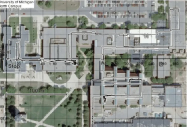
Quigley et al. (2010) present a complete system consisting of methods for map-building, collection of refer- ence data and a localization method basing on low-cost smartphone sensors. In the map-building step, a robot equipped with laser scanners builds the required map using Simultaneous Localization and Mapping (SLAM), before a human operator visits the mapped area again with a sensor backpack and the consumer- grade device to be used during localization. The online localization uses the smartphone camera by ex- tracting SURF keypoints (looked up in the reference data), and combines this information with WiFi signal strength based positioning. This is complemented by a particle filtering operation in order to reach sub- meter precision.
Elloumi et al. (2013) fully concentrate on images and their vanishing points. In the offline phase the vanish- ing points in each key frame are extracted using the Canny edge detector (Canny, 1986), the probabilistic Hough transform (Kiryati et al., 1991) and a RANSAC (RANdom SAmple Consensus) filtering operation.
From the information about the vanishing points of the scene, the camera orientation is estimated. For the localization during the online phase, the closest key frame is identified using the Harris corner detector and zero-mean normalized cross-correlation. The position associated with the key frame and an additional angular deviation estimation result in the final position. The experiments carried out by use of a calibrated smartphone camera reveal errors of around 0.5 metres, even at higher walking speeds and with an offset from the offline phase’s path.
An example for image-based positioning by matching to an available floorplan can be found in Hile and Borriello (2008). The authors describe the detection of the floor in the image captured by a camera phone.
The position estimation with respect to an available floorplan is carried out by matching points of both
representations of the floor using a RANSAC method.
2 Indoor positioning and tracking 21 Commercially, none of these methods have been put to use. Instead, companies like PinPoint 8 employ camera scanned QR code tags in order to provide the user’s current (discrete) position with respect to a map.
2.1.3 Sound
Examples from animality - e.g. whales and bats - demonstrate the applicability of (ultra)sound for distance measurements. The knowledge of the sender’s or receiver’s location(s) together with the distance measure- ment enables the position computation for the navigating subject using lateration in sound-based indoor positioning systems. Furthermore, the specific acoustic background fingerprint of rooms can be used for room-level positioning.
While Madhavapeddy et al. (2003) illustrate the possibility to leverage audible sound signals for position determination with room granularity, a method for absolute positioning was presented by Mandal et al.
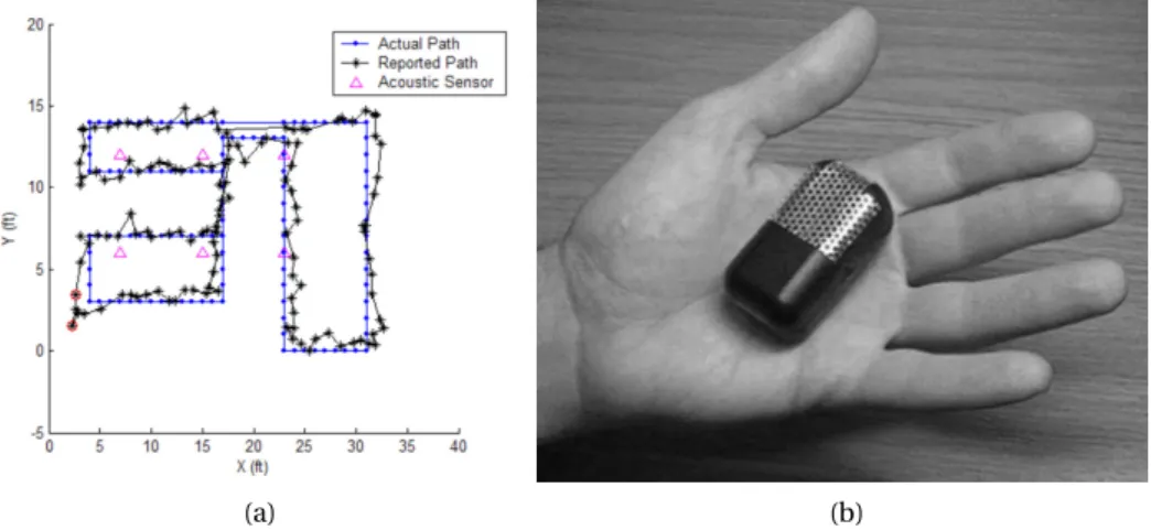
(2005), aptly named “Beep”. Its infrastructure consists of microphones distributed throughout the desired working volume of the system and an existing Wi-Fi network, at the client no additional hardware to the one existing e.g. in off-the-shelf mobile phones is needed. Upon the user request for a position update, time synchronization over the Wi-Fi network is established before the client emits an audio signal with pre-defined frequency and duration. After detection using the microphones, the system’s central server estimates the time of flight and computes the distances, which can be used to compute the client’s position using 3D multilateration up to an accuracy of 0.6 metres in 97% of cases in a testbed of 10x5 square meters (compare figure 2.2a). Hoflinger et al. (2012) use the same principle, but add a self-calibration step instead of manual referencing of the receivers. Their ASSIST system reaches 0.34 metres of error.
Rishabh et al. (2012) add audible signals to controlled ambient sounds like music using pseudo-random noise. The signal recorded by the client is sent to the server which performs cross-correlation in order to determine the time-of-arrival and estimate the client’s location and time offset. Due to the unfavourable signal-to-noise ratio, long recordings or continuous tracking are necessary, however, a positioning error of 0.2 metres can be achieved.
More common than audible sound, however, is the use of ultrasound. The most obvious motivation for its use over audible sound is the removal of user disturbance. Furthermore, the signals are less prone to interferences by talking people, music or other human-generated sound. An overview over various methods can be found in Holm (2012).
Harter et al. (2002) present a positioning system based on ultrasound as part of their context-aware system enabling digital working environments to follow their users to the respectively nearest available worksta- tion. The clients are mobile units, the so-called Bats (see figure 2.2b), which contain a radio transmitter and an ultrasonic transducer and have a unique identifier. The infrastructure consists of a base station and receivers placed on the ceilings. The base station periodically resets the receivers and transmits a radio message containing the identifier of the Bat which is requested to emit an ultrasonic impulse. The follow- ing distance computation from the signal’s travelling times takes the ambient temperature into account.
Additionally, an outlier rejection was incorporated into the multilateration position computation. The ori- entations of clients can be determined using multiple Bats or by the use of the object’s ultrasonic shadow.
8
http://www.pinpoint-navigation.com/?l=en (last visited 2nd February 2016)
22 2 Indoor positioning and tracking The evaluation in a 10m³ testbed yielded an accuracy of 9 centimeters. Using mobile phones as transmit- ters (instead of dedicated mobile units) and Time Difference of Arrival in order to eliminate the need for synchronization, Filonenko et al. (2013) reach 8.2-18.1 centimetres of error. Errors of 4.2 centimetres are reported by Sato et al. (2011), who densely pack the receivers and thus have to increase the distance meas- urement accuracy using the extended phase accordance method.
Instead of active clients answering to a radio frequency (RF) request, Priyantha et al. (2000)’s “Cricket” sys- tem makes use of the difference between the speeds of sound and light and also adds the transmission of the ultrasonic pulse to the beacons. The beacons concurrently send a RF and ultrasonic pulse, the clients, upon receiving the RF pulse, turn on the ultrasonic receiver and listen for the ultrasonic pulse. The distance can be derived from the difference between the respective times-of-arrival of both pulses. To ensure privacy and ease of implementation, however, the locations of the beacons are unknown, and only the nearest beacon is identified. Thus, the system delivers symbolic coordinates and the positioning accuracy is dependent on the arrangement of the beacons, a 2.4x2.4 metres grid was proven to be feasible. Using smartphones as receivers, Lopes et al. (2013) can establish the system’s synchronization over Wi-Fi. Thus, 7.3 centimetres of error in a 7x7 square metres test bed can be reached.
Taking the principle described in Priyantha et al. (2000) one step further, the DOLPHIN system presented in Fukuju et al. (2003) consists of dual-purpose nodes acting as senders and receivers, some of which act as reference nodes. The signals from the reference nodes as well as the previously localized nodes are used to subsequently compute the position of other nodes using multilateration. The system was tested in a small testbed of 2x2.5 square metres and yielded an error of less than 5 centimetres for nodes directly positioned by reference nodes. All other nodes suffer from error propagation, which results in 10-15 centimetres of error for nodes on the second layer.
Moving away from lateration, Tarzia et al. (2011) use the acoustic background spectrum audible in every room in a fingerprinting method. Therefore, they compute the power spectogram of a 30-second sound recording at different positions in the room, ensure transient noise rejection, and normalize it. In the online phase, the user’s position is determined as the nearest neighbour in the fingerprint database. The system is able to identify the correct room in 69% of cases, independent of the use of professional audio recording equipment or their iOS BatPhone implementation. Probably more significant is the achieved 92% adjacent room distinction which makes the method complementary to Wi-Fi fingerprinting, promising good results for a system combining both methods.
(a) (b)
Figure 2.2: Sound-based systems: a) results from the Beep system presented by Mandal et al. (2005), b) an Active Bat
unit as presented in Harter et al. (2002)
2 Indoor positioning and tracking 23 Medina et al. (2012), in contrast, evaluate the use of ultrasound in a RSSI-based system, reaching a standard deviation of 4.5 centimetres using RSSI values derived by signal propagation modeling. As the cell size of ultrasound systems does not exceed single rooms, genuine fingerprinting methods are rare. However, Ben- Moshe et al. (2013) developed a method basing on TDOA fingerprints and evaluted it using off-the-shelf smartphones, speakers and a quad channel sound card. They come to the conclusion, that, while TDOA measurements are insufficiently accurate for the purpose of lateration, they are highly stable and usable for fingerprinting.
Sonitor 9 offers a commercial system basing on ultrasound that is aimed at asset and patient tracking in hospitals. While mainly delivering room granularity, the company states that an accuracy of 30 centimetres is feasible.
2.1.4 Electro-magnetic signals
As shown above, indoor positioning systems using light or sound can deliver high accuracies. However, in the confined space in buidling floors divided into rooms and corridors, their range is restricted by the lim- ited line-of-sight. Electro-magnetic signals, on the other hand, are able to penetrate walls and thus enlarge the area covered by any positioning system based on them. Furthermore, for many signals, e.g. bluetooth, FM radio or WiFi signals, senders are either cheap (off-the-shelf) or already installed for communication purposes. Thus, receivers for a range of electro-magnetic signals are already found in common modern hardware such as smart phones.
GPS and Pseudolites
Most publications reporting on scientific progress in the field of indoor positioning motivate the described efforts by the unavailability of GNSSs in indoor environments. Due to signal attenuation, interferences, and multipath effects, GNSS signals either completely vanish in noise, cannot be tracked in order to derive stable position fixes, or deliver results prone to very high errors. Lachapelle (2004) assesses these generally known facts regarding the signals’ availability, accuracy, continuity and reliability. The low availability of satellite signals in indoor environments can be overcome by an available clock constraint and a low-cost MEMS barometer, resulting in two satellites being sufficient for a 2D position fix. The largest influences on accuracy are high-noise, echo-only or multipath signals as well as the degraded geometry of the available satellite constellations. Continuity depends on rapid temporal and spatial decorrelations of multipath sig- nals and rapidly changing satellite constellations. Using four typical building interiors, Lachapelle (2004) describes the achievable accuracies as around 5 metres (wooden building, kinematic measurement mode), 10-30 metres (north american residence, static), 25-45 metres (sports arena made of concrete, kinematic) and 75 metres (office building, static). Errors of these dimensions are confirmed by Eissfeller et al. (2005) as well as Schon and Bielenberg (2008).
While reliably achievable indoor positioning accuracies in this scale would be acceptable e.g. in emergency, safety-of-life scenarios in order to locate the building the user is in, most other intended purposes for indoor positioning require much higher accuracies. The use of Assisted GNSS (AGNSS), basing on Satellite Based
9
www.sonitor.com (last visited 2nd February 2016)
24 2 Indoor positioning and tracking Augmentation Systems like EGNOS and MSAS, is reported to enable indoor accuracies down to 10 metres (Mautz, 2009). For further improvement, terrestrial time-synchronized transceivers - so-called pseudolites - have to be used. Kuusniemi et al. (2012) present an evaluation of the combination of high-sensivity GNSS and pseudolites. In their scenario, the pseudolites are used as beacons, i.e. contribute to the particle filter only by their proximity information. In a three floor building, the use of pseudolites and a simple map- matching approach results in an accuracy of 7.6/6.6 metres (1st/3rd floor) in contrast to 15.8/11.7 metres for the GNSS-only solution. Locata 10 is one example for commercially available pseudolites systems. According to the tests presented in Rizos et al. (2013) (open indoor space, using a directional antenna, 2D positioning), the achievable accuracy is 1.5 centimetres (95%).
RFID and Bluetooth
With SpotON, Hightower et al. (2000) presents an RFID-(radio frequency identification)-based system using off-the-shelf base stations and active badges. The signal strengths measured by the base stations are repor- ted to a central server which computes the position using lateration and the inverse square law. According to the authors, the evaluated 3-metre-accuracy is due to the limited resolution of the signal strength measure- ments. Experiments with a prototype system with new hardware indicated sub-metre accuracy. Similarly, Ni et al. (2004) employ commercially available hardware, however, try to improve the accuracy by adding reference tags with known positions. This method keeps the needed number of more expensive readers low and allows for a dynamic assessment of the current environmental conditions (interferences induced by moving people etc.). Using four readers and 16 reference tags, one meter of error (50%) is reached in a 4x9 square metres testbed.
Commercial systems using RFID are sold by vendors including WhereNet 11 , Radianse 12 and Versus 13 . The primary designated uses for these systems are found in asset management, retail, and the health system, i.e. asset and patient tracking in hospitals. WhereNet specifies 1.6 metres (95%) as location accuracy of the WhereLAN system.
Before the emergence of Bluetooth low-energy (BLE), commercial systems leveraging bluetooth signals were sold by Topaz 14 and Quuppa 15 (the former indoor positioning team of Nokia). Topaz states a room level accuracy of up to 2 metres and a latency of 15-30 seconds. In contrast, Quuppa’s High Accuracy In- door Positioning system is able to achieve 0.3-1 metres in real-time using AOA and dedicated tags. Soon, however, the same accuracy level is expected to be achieved with off-the-shelf BLE-enabled handsets.
The very low energy consumption of hardware following the BLE standard enables the production of beacons which run for several months or even years on a single coin cell battery. Furthermore, BLE receivers barely affect the run times of smartphones or similar devices and can be left running all the time. Combining these
10
http://www.locata.com (last visited 2nd February 2016)
11
http://www.zebra.com/gb/en.html (last visited 2nd February 2016)
12
www.radianse.com (last visited 2nd February 2016)
13
www.versustech.com (last visited 2nd February 2016)
14
http://www.tadlys.co.il/ (last visited 2nd February 2016)
15
http://quuppa.com/ (last visited 2nd February 2016)
2 Indoor positioning and tracking 25 two characteristics, smartphones in the proximity of a beacon can detect it and location-based events at- tached to the beacon like e.g. an advertisement or a price discount can be triggered. If the IDs of the beacons are not included in a database stored locally in the smartphone, however, their meaning has to be reques- ted from a network database, which reveals the user’s position. While this raises privacy issues on the user side, it is a welcome feature for shop owners eager to analyse customer behaviour. Proximity-based identi- fication is the intended use of BLE beacons, however, first experiments employing them in more accurate multilateration strategies were presented, in research (Salas, 2014) and also commercially available 16 . BLE beacons are sold by Apple (iBeacons), estimote 17 , stick’n’find 18 and qualcom 19 . Recently, Samsung joined with their Proximity 20 system.
UltraWideBand (UWB)
According to the FCC (2002), UltraWideBand is a frequency band with absolute bandwidth wider than 500MHz or a relative bandwidth wider than one fourth of its mean frequency. Blankenbach et al. (2007) furthermore mention that, while the frequency band is license free in the United States, power restrictions apply due to the overlap with other frequency bands (e.g. WiFi). Despite these power restrictions, UWB bears a low sensitivity to interferences, multipath effects, and affords a good penetration of materials. Thus, this signal band seems to be an ideal base for indoor positioning systems.
As an example of ongoing UWB indoor positioning research, Blankenbach et al. (2007) describe experiments covering distance measurements using UWB without obstacles as well as through different materials, result- ing in differences to ground truth measurements of below 10 centimetres up to 30 centimetres, respectively.
Concerning the feasibility of 3D positioning in indoor environments, the authors give a short description of an experiment delivering errors in the centimetre range.
Due to the characteristics of UWB, there are some commercial systems already available in the market, e.g.
by Zebra Technologies 21 , BlinkSight 22 or UbiSense 23 . For example, the UbiSense Real-Time Location System (RTLS) leverages a combination of TOA and AOA in order to track assets or personnel equipped with UWB emitters in 3D with an accuracy of down to 30 centimetres and a high precision and reliability.
FM radio, TV and cell phone signals
The main advantage of the use of FM radio, TV and cell phone (GSM, UMTS, LTE) signals for positioning purposes lies in the fact that their frequencies are licensed. Thus, they do not interfere with signals emitted
16
http://www.nextome.org/en/index.php (last visited 2nd February 2016)
17
http://estimote.com/
18
https://www.sticknfind.com/ (last visited 2nd February 2016)
19
https://www.gimbal.com/ (last visited 2nd February 2016)
20
https://placedge.samsung.com/ (last visited 2nd February 2016)
21
http://www.zebra.com/id/zebra/na/en/index/products/location/ultra_wideband.htm (last visited 2nd Feb- ruary 2016)
22
http://www.blinksight.com/ (last visited 2nd February 2016)
23
http://www.ubisense.net/en/products-and-services/rtls-products.html (last visited 2nd February 2016)
26 2 Indoor positioning and tracking by other electronic devices such as microwave ovens. Because their emitters are located outside of the building the position shall be computed in, the signals are more likely to be available in events of emergency than those of locally installed systems. Lastly, the networks are reconfigured very infrequently and thus the signals should bear a better long-time stability than e.g. WiFi.
Despite being licensed, the transmission of low-power short-range FM radio signals is permitted in many countries. Matic et al. (2010) and Popleteev (2011) make use of this permission, deploying FM radio trans- mitters in the measuring volume and using an off-the-shelf smartphone as the client of their fingerprinting- based indoor positioning system. Matic et al. (2010) describe position estimation experiments using k nearest neighbours as well as Gaussian process regression, reaching accuracies of 3.88 metres respectively 2.65 metres (95%). In combination with Wi-Fi fingerprints, these results can be improved to 0.85 metres (95%).
In contrast to this approach which is mainly usable for the low-cost improvement of Wi-Fi fingerprinting, Moghtadaiee et al. (2011) present results from a similar approach using only available FM radio signals. Tak- ing offline-phase sample measurements at 150 points for a 11x23m² test bed, they reach an accuracy of 6.4 metres (95%). Chen et al. (2012), on the other hand, augment the available FM fingerprints with additional information about the signal’s physical layer: signal-to-noise ratio, multipath and frequency offset. Concen- trating on room-level positioning, because this information can be crowdsourced using people checking in to stores, they also assess fine-grain positioning with fingerprints sampled at 30 centimetres distance. While positioning using Wi-Fi reaches an accuracy of around 3 meters in this scenario, FM fingerprints deliver an impressive accuracy of 30 centimetres in 90% of cases.
Rabinowitz and Spilker (2005) describe a system building on TV signals in combination with AGPS, which - reaching 30-50 metres of indoor accuracy - is supposed to be E911 compliant. The authors tried to com- mercialize the system in a company called Rosum, however, without success.
Cell phone signals - GSM as well as UMTS, LTE - are another class of signals which are ubiquitously available.
Depending on the country, GSM operates on different frequency bands in the range between 380MHz and 2000MHz, e.g. in Germany on 900MHz and 1800MHz, which are subdivided into physical channels 24 , which in turn are split into logical channels 25 . GSM cells are defined by the areas covered by the different antennas forming a base station. The accuracies of GSM positioning methods Mautz (2009) presents (see figure 2.1) refer to network-based methods as described in Schwieger (2007).
More recent research, however, builds on fingerprinting methods employing cell phone signals. While earlier work on outdoor positioning only used the strongest or the six strongest cells for fingerprinting, Ot- sason et al. (2005) present “wide signal strength fingerprints” consisting of the six strongest cells extended by readings from 29 additional channels. For the online position estimation, they use k nearest neighbours search, additionally geographically clustered by k-means. The evaluation comprises floor classification and within-floor positioning using GSM as well as Wi-Fi fingerprints for comparison. The within-floor GSM positioning shows an accuracy similar to Wi-Fi between 2.5 and 5.4 metres (50%). Denby et al. (2009), des- pite using the full GSM band for fingerprinting and more sophisticated position retrieval techniques like Support Vector Machines and Gaussian Processes, only evaluated the room identification potential of their
24
using Frequency Division Multiple Access (FDMA)
25
using Time Division Multiple Access (TDMA)
2 Indoor positioning and tracking 27 system, reaching 97.8% in a testbed with five rooms. Birkel and Weber (2012) deploy short-range UMTS senders at the same locations as Wi-Fi access points, reaching an accuracy of 7 metres (80%) with a received signal strength fingerprinting method.
Magnetism
Due to the various interferences produced by electronic installations, e.g. elevator motors or electro-magnetic fields, magnetometers measuring the earth’s magnetic field tend to be of marginal value for the orientation determination in building interiors. However, it has been shown that artificial magnetic fields as well as fingerprinting approaches basing on the local perturbances of the geomagnetic field can be leveraged for indoor positioning.
One solution found in related work consists of utilizing synthetic magnetic fields. The foundations to po- sition estimation using these fields were published by Raab et al. (1979), however, with the emergence of 3-axis magnetometers as standard sensor equipment of smartphones this method was revisited by Blanken- bach and Norrdine (2010); Norrdine and Blankenbach (2013). As infrastructure, static inductors are set up which sequentially emit artificial magnetic fields following the Time Division Multiplexing (TDOA) method.
In order to eliminate the influence of interfering fields, a differential measuring principle is applied by se- quential reversal of the receiver’s polarity. In the authors’ 2D experiments, three static inductors were suffi- cient to reach a position error of up to 0.5 metres, even with low-cost smartphone sensors.
Commercial positioning systems employing artificial magnetic fields are available, e.g. by Ascension 26 and Polhemus 27 . However, these aim at low-range positioning in medical and motion capturing applications and therefore are not applicable for indoor positioning.
In contrast to generating artificial fields in order to provide a stable, known field to mobile magnetomet- ers, there have been efforts to leverage the effects of local variations interfering with geomagnetism. For example, Chung et al. (2011) describe an experimental system building on a magnetic fingerprint map. As magnetometer readings alone provide at most a three-dimensional feature vector, the optimal number of sensors and their displacement are identified experimentally. Using three testbeds, the fingerprints are col- lected in various orientations on a 0.6 metres grid. During the online phase the position is selected as the least RMS neighbour, leading to a mean error of between 2.84 and 6.28 metres for the different testbeds, while 75% of all measurements show less than one metre of error. Adding a rudimentary mobility model causes an increase to one metre error in 88% of cases. The authors also examined the long-term stability as well as the sensitivity to nearby objects like elevators, concluding that in combination with Wi-Fi fingerprint data an accuracy improvement to 0.45 metres would be possible. Li et al. (2012) report similar results, in addition they evaluated the feasibility to detect the correct floor in a 5-floor building to be between 72 and 90%. Song et al. (2012) come to the conclusion, that geo-magnetism based systems are able to outperform Wi-Fi fingerprint-based systems.
A commercial system leveraging fingerprints of the geomagnetic field’s disturbances is offered by indoorAt- las 28 . The web page presents tutorials explaining how to upload and georeference an available indoor map
26
http://www.ascension-tech.com/ (last visited 2nd February 2016)
27
http://polhemus.com/ (last visited 2nd February 2016)
28