der Bayerischen Akademie der Wissenschaften
Reihe C Dissertationen Heft Nr. 767
Ali Mohammad Khosravani
Automatic Modeling of Building Interiors Using Low-Cost Sensor Systems
München 2016
Verlag der Bayerischen Akademie der Wissenschaften in Kommission beim Verlag C. H. Beck
ISSN 0065-5325 ISBN 978-3-7696-5179-9
der Bayerischen Akademie der Wissenschaften
Reihe C Dissertationen Heft Nr. 767
Automatic Modeling of Building Interiors Using Low-Cost Sensor Systems
Von der Fakultät Luft- und Raumfahrttechnik und Geodäsie der Universität Stuttgart
zur Erlangung der Würde eines
Doktors der Ingenieurwissenschaften (Dr.-Ing.) genehmigte Abhandlung
Vorgelegt von
M.Sc. Ali Mohammad Khosravani
aus Shiraz, Iran
München 2016
Verlag der Bayerischen Akademie der Wissenschaften in Kommission beim Verlag C. H. Beck
ISSN 0065-5325 ISBN 978-3-7696-5179-9
Adresse der Deutschen Geodätischen Kommission:
Deutsche Geodätische Kommission
Alfons-Goppel-Straße 11 ! D – 80539 München
Telefon +49 – 89 – 230311113 ! Telefax +49 – 89 – 23031-1283 /-1100 e-mail hornik@dgfi.badw.de ! http://www.dgk.badw.de
Hauptberichter: Prof. Dr.-Ing. habil. Dieter Fritsch Mitberichter: Prof. Dr.-Ing. habil. Volker Schwieger Tag der mündlichen Prüfung: 09.12.2015
Diese Dissertation ist auf dem Server der Deutschen Geodätischen Kommission unter <http://dgk.badw.de/>
sowie auf dem Server der Universität Stuttgart unter <http://elib.uni-stuttgart.de/opus/doku/e-diss.php>
elektronisch publiziert
© 2016 Deutsche Geodätische Kommission, München
Alle Rechte vorbehalten. Ohne Genehmigung der Herausgeber ist es auch nicht gestattet,
die Veröffentlichung oder Teile daraus auf photomechanischem Wege (Photokopie, Mikrokopie) zu vervielfältigen.
ISSN 0065-5325 ISBN 978-3-7696-5179-9
This dissertation is gratefully dedicated to my beloved mother, for her endless love and encouragements, and to my late father.
Kurzfassung
Die dreidimensionale Rekonstruktion von Innenraumszenen zielt darauf ab, die Form von Gebäudeinnenräumen als Flächen oder Volumina abzubilden. Aufgrund von Fortschritten im Bereich der Technologie entfernungsmessender Sensoren und Algorithmen der Computervision sowie verursacht durch das gesteigerte Interesse vieler Anwendungsgebiete an Innenraummodellen hat dieses Forschungsfeld in den letzten Jahren zunehmend an Aufmerksamkeit gewonnen. Die Automatisierung des Rekonstruktionsprozesses ist weiterhin Forschungsgegenstand, verursacht durch die Komplexität der Rekonstruktion, der geometrischen Modellierung beliebig geformter Räume und besonders im Falle unvollständiger oder ungenauer Daten. Die hier vorgestellte Arbeit hat die Erhöhung des Automatisierungsgrades dieser Aufgabe zum Ziel, unter der Verwendung einer geringen Anzahl an Annahmen bzgl. der Form von Räumen und basierend auf Daten, welche mit Low-Cost- Sensoren erfasst wurden und von geringer Qualität sind.
Diese Studie stellt einen automatisierten Arbeitsablauf vor, welcher sich aus zwei Hauptphasen zusammensetzt. Die erste Phase beinhaltet die Datenerfassung mittels eines kostengünstigen und leicht erhältlichen Sensorsystems, der Microsoft Kinect. Die Entfernungsdaten werden anhand von Merkmalen, welche im Bildraum oder im 3D Objektraum beobachtet werden können, registriert. Ein neuer komplementärer Ansatz für die Unterstützung der Registrierungsaufgabe wird präsentiert, da die diese Ansätze zur Registrierung in manchen Fällen versagen können, wenn die Anzahl gefundener visueller und geometrischer Merkmale nicht ausreicht. Der Ansatz basiert auf der Benutzerfußspur, welche mittels einer Innenraumpositionierungsmethode erfasst wird, und auf einem vorhandenen groben Stockwerksmodell.
In der zweiten Phase werden aus den registrierten Punktwolken mittels eines neuen Ansatzes automatisiert hochdetaillierte 3D-Modelle abgeleitet. Hierzu werden die Daten im zweidimensionalen Raum verarbeitet (indem die Punkte auf die Grundrissebene projiziert werden) und die Ergebnisse werden durch eine Extrusion in den dreidimensionalen Raum zurückgewandelt (wobei die Raumhöhe mittels einer Histogrammanalyse der in der Punktwolke enthaltenen Höhen erfasst wird). Die Datenanalyse und -modellierung in 2D vereinfacht dabei nicht nur das Rekonstruktionsproblem, sondern erlaubt auch eine topologische Analyse unter Verwendung der Graphentheorie. Die Leistungsfähigkeit des Ansatzes wird dargestellt, indem Daten mehrerer Sensoren verwendet werden, die unterschiedliche Genauigkeiten liefern, und anhand der Erfassung von Räumen unterschiedlicher Form und Größe.
Abschließend zeigt die Studie, dass die rekonstruierten Modelle verwendbar sind, um vorhandene grobe Innenraummodelle zu verfeinern, welche beispielsweise aus Architekturzeichnungen oder Grundrissplänen abgeleitet werden können. Diese Verfeinerung wird durch die Fusion der detaillierten Modelle einzelner Räume mit dem Grobmodell realisiert. Die Modellfusion beinhaltet dabei die Überbrückung von Lücken im detaillierten Modell unter Verwendung eines neuen, auf maschinellem Lernen basierenden Ansatzes. Darüber hinaus erlaubt der Verfeinerungsprozess die Detektion von Änderungen oder Details, welche aufgrund der Generalisierung des Grobmodells oder Renovierungsarbeiten im Gebäudeinnenraum fehlten.
6
Abstract
Indoor reconstruction or 3D modeling of indoor scenes aims at representing the 3D shape of building interiors in terms of surfaces and volumes, using photographs, 3D point clouds or hypotheses. Due to advances in the range measurement sensors technology and vision algorithms, and at the same time an increased demand for indoor models by many applications, this topic of research has gained growing attention during the last years. The automation of the reconstruction process is still a challenge, due to the complexity of the data collection in indoor scenes, as well as geometrical modeling of arbitrary room shapes, specially if the data is noisy or incomplete. Available reconstruction approaches rely on either some level of user interaction, or making assumptions regarding the scene, in order to deal with the challenges. The presented work aims at increasing the automation level of the reconstruction task, while making fewer assumptions regarding the room shapes, even from the data collected by low-cost sensor systems subject to a high level of noise or occlusions. This is realized by employing topological corrections that assure a consistent and robust reconstruction.
This study presents an automatic workflow consisting of two main phases. In the first phase, range data is collected using the affordable and accessible sensor system, Microsoft Kinect. The range data is registered based on features observed in the image space or 3D object space. A new complementary approach is presented to support the registration task in some cases where these registration approaches fail, due to the existence of insufficient visual and geometrical features. The approach is based on the user’s track information derived from an indoor positioning method, as well as an available coarse floor plan.
In the second phase, 3D models are derived with a high level of details from the registered point clouds. The data is processed in 2D space (by projecting the points onto the ground plane), and the results are converted back to 3D by an extrusion (room height available from the point height histogram analysis). Data processing and modeling in 2D does not only simplify the reconstruction problem, but also allows for topological analysis using the graph theory. The performance of the presented reconstruction approach is demonstrated for the data derived from different sensors having different accuracies, as well as different room shapes and sizes.
Finally, the study shows that the reconstructed models can be used to refine available coarse indoor models which are for instance derived from architectural drawings or floor plans. The refinement is performed by the fusion of the detailed models of individual rooms (reconstructed in a higher level of details by the new approach) to the coarse model. The model fusion also enables the reconstruction of gaps in the detailed model using a new learning-based approach. Moreover, the refinement process enables the detection of changes or details in the original plans, missing due to generalization purposes, or later renovations in the building interiors.
Contents
Kurzfassung ... 5
Abstract ...6
1. Introduction ...11
1.1. Motivation ... 11
1.2. Objectives ... 13
1.3. Outline and Design of the Thesis ... 13
2. Overview of Indoor Data Collection Techniques...15
2.1. State-of-the-Art Sensors for 3D Data Collection ... 16
2.1.1. Laser Scanners ... 17
2.1.2. 3D Range Cameras ... 22
2.2. The Registration Problem ... 31
2.2.1. Registration Using Point Correspondences in the Point Clouds ... 31
2.2.2. Registration by the Estimation of the Sensor Pose ... 33
3. Data Collection using Microsoft Kinect for Xbox 360 ...36
3 .. Point Cloud Collection by Kinect ... 36 1 3.1.1. System Interfaces and SDKs ... 36
3.1.2. System Calibration ... 36
3.1.3. Generation of Colored Point Clouds ... 39
3.2. Point Clouds Registration ... 42
3.2.1. Point Clouds Registration Based on RGB and Depth Information ... 42
3.2.2. Point Clouds Registration Based on an Indoor Positioning Solution and Available Coarse Indoor Models ... 43
3.3. Kinect SWOT Analysis ... 49
4. Overview of Available Indoor Modeling Approaches ...50
4.1. Classification of Available Modeling Approaches ... 51
4.2. Iconic Approaches ... 52
4.2.1. Image-Based Modeling ... 52
4.2.2. Range-Based Modeling ... 57
4.2.3. Modeling Based on Architectural Drawings ... 60
4.3. Symbolic Approaches ... 63
8
5. Automatic Reconstruction of Indoor Spaces ...65
5.1. Point Cloud Pre-Processing ... 66
5.1.1. Outlier Removal ... 66
5.1.2. Downsampling ... 67
5.1.3. Noise Removal ... 67
5.1.4. Leveling the Point Cloud ... 68
5.1.5. Height Estimation and Furniture Removal ... 69
5.2. Reconstruction of Geometric Models ... 70
5.2.1. Generation of Orthographic Projected Image ... 70
5.2.2. Binarization ... 71
5.2.3. Morphological Image Processing ... 72
5.2.4. Estimation of the Lines Representing the Walls in 2D ... 73
5.2.5. Topological Corrections ... 76
5.2.6. 2D to 3D Conversion of Reconstructed Models ... 81
6. Experimental Results and Analysis ...82
6.1. Kinect System Calibration and Accuracy Analysis ... 82
6.1.1. System Calibration ... 82
6.1.2. Accuracy of Kinect Range Measurements ... 85
6.2. Evaluation of the Reconstruction Approach ... 88
6.2.1. Parameter Selection in Different Scenarios ... 88
6.3. Quality of the Reconstructed Models ... 93
7. Application in the Refinement of Available Coarse Floor Models ...95
7.1. Registration of Individual Detailed Models to an Available Coarse Floor Model ... 96
7.1.1. Approximate Registration ... 96
7.1.2. Fine Registration ... 97
7.2. Fusion of Detailed Models to the Coarse Model ... 99
8. Conclusion...103
8.1. Summary... 103
8.2. Contributions ... 103
8.3. Future Work ... 104
Appendix A. Point Cloud Registration – Fundamental Principles ...106
A.1. Closed-Form Solution ... 107
A.2. Iterative Solution (ICP) ... 109
Appendix B. RANSAC ...112
Appendix C. SLAM Problem ...113
Appendix D. Hough Transform ...115
D.1. Standard Hough Transform ... 115
D.2. Progressive Probabilistic Hough Transform ... 116
Appendix E. Reconstruction of Detailed Models – Case Studies ...117
References ...123
Relevant Publications ...130
Curriculum Vitae ...131
Acknowledgment ...132
10
1. Introduction
1.1. Motivation
Indoor modeling addresses the reconstruction of 2D and 3D CAD models of building interiors by means of surfaces or volumes. Such models can be derived from photographs by the extraction and matching of features of interest, or from point clouds by the fitting geometric primitives.
Models of buildings interior structure are demanded by many applications to support a variety of needs, from navigation to simulation. In robotics and computer vision, existence of a map or simultaneous mapping is essential for localization of the user or a mobile robot. In virtual city models, interior models constitute the levels-of-detail 4 (LOD4) models (according to OGC standard CityGML (Kolbe et al., 2005)), to support many spatial-based applications such as GIS, urban planning, risk management, emergency action planning, environmental simulation, navigation, etc.. In Building Information Modeling (BIM), which is used for supporting construction, planning, design, and maintaining infrastructures, interior models are the geometric basis of semantic information. In architecture, virtual indoor models support interior designers to have a realistic and more precise impression about spaces.
The most important challenge in the reconstruction of indoor models is the time and costs of data collection and generating such models. In practice, this task is mainly performed using manual and semi-automatic approaches, and therefore the user qualifications play an important role in the speed and accuracy of the process. According to the comparison made by Panushev and Brandt (2007), the reconstruction of average-sized building interiors takes several months, although modeling single objects can be a fairly quick task. Therefore, the automation of this process is required. This automation is still a challenge, due to the existence of clutter, complexity of the shape of the interior and challenges in the data collection.
Indoor data collection is mostly performed from ground level viewpoints, and therefore is more complex and challenging in comparison with airborne and remote data collection. Moreover, data collection platforms delivering high accuracy data (e.g. Terrestrial Laser Scanners (TLS)) are usually heavy and expensive, and therefore large-scale data collection is time consuming and costly. However, development of low-cost range measurement sensors has recently increased the focus on range-based indoor mapping. According to Luhmann et al. (2014), the mass market effect of the consumer-grade 3D sensing camera Microsoft Kinect (over 10 million units in circulation), had a significant impact on the photogrammetric community where the number of 3D sensing systems is in the range of 1000s.
The registration of the point clouds collected by such low-cost and handheld systems is also an active research area; as will be seen later, this task can be a challenge in scenarios having a poor texture or insufficient geometrical features. Presented works by Henry et al. (2012), Newcombe et al. (2011), Whelan et al. (2013) consider the Kinect a suitable platform for a fast and affordable data collection.
Google Project Tango, Structure Sensor and DPI-7/8 are examples of commercial solutions developed so far, for the collection of 3D data from building interiors, as the user walks through space. For the registration of the collected point clouds, the systems benefit from the geometric information extracted
12 1. Introduction from the range images, or observations made in color image space, or a combination of both information for an accurate pose estimation. Therefore, the systems turned to be fragile in scenarios that the mentioned sources of information are not available or insufficient, such as scenes with low visual or geometrical features (e.g. hallways). Therefore, other sources of information and new strategies shall be considered to fill the gap in the available registration approaches.
Despite the fact that indoor data collection has already been studied by many researchers, and is facilitated due to advances in sensor technology and vision algorithms, less attention is still paid to the reconstruction of CAD models based on the collected data. Moreover, although some reconstruction approaches are already available, the quality and density of the collected data by low-cost sensor systems are not always consistent with the assumptions made by the approaches. In other words, affordability comes with loss of quality and trade-offs; data collected by low-cost sensor systems are subject to more noise, gaps and other artifacts that make the reconstruction process more challenging than before. Due to the complexity of indoor scenes, existence of gap and clutter, and extreme conditions for the registration of collected point clouds, still a general and fully automatic indoor reconstruction approach does not exist. Available approaches rely either on some level of user interaction, or make assumptions regarding the room shapes, quality of the collected data, etc.
Commercial software solutions such as Leica Cyclone and Leica CloudWorx are widely used for modeling from the collected point clouds; however, they are based on a high level of user interaction.
A strategy for the automation of this process is proposed for instance by Budroni and Böhm (2009) using a linear and rotational plane sweeping algorithm, however, under the assumption that the walls are parallel or perpendicular to each other (Manhattan-world scenario). Moreover, the ceiling and floor points have to be collected in this modeling approach (for the cell decomposition process), which is a challenge for low-cost mobile mapping systems, due to the poor texture and 3D information required for the registration of the point clouds captured from different viewpoints. Another example of automatic reconstruction of indoor scenes is presented by Previtali et al. (2014), based on the RANSAC algorithm for the extraction of planar features. Although this algorithm can model rooms with more general shapes, still the collection of floor or ceiling points for the cell decomposition is necessary. Another category of approaches converts the modeling problem from 3D to 2D, and extract line segments corresponding to walls by processing images derived from the projection of points onto the ground plane. Okorn et al. (2010) use the Hough transform for this purpose; however, the resulting 2D plan does not represent a topologically correct model. Adan and Huber (2011) use a similar approach, but add more semantic information into the models and deal with occlusions using a ray- tracing algorithm, assuming 3D data is collected from fixed and known locations. Valero et al. (2012) further improve the results using a more robust line detection algorithm and considering some topological analyses. However, this approach requires a dense and high quality input point cloud, which is a challenge to fulfill using low-cost sensor systems.
Therefore, new approaches are required to fill the gap between the new data collection strategies and available reconstruction approaches, by making fewer assumptions regarding the point cloud quality, data collection strategy and different room shapes, and at the same time dealing with the gaps in the data.
1.2. Objectives
Regarding the mentioned gaps in the previous section, this work aims at increasing the automation level, and at the same time the performance of the reconstruction process (i.e. modeling arbitrary shapes with a higher level of detail), with a focus on the data collected by low-cost sensor systems. For this purpose, the following objectives shall be fulfilled in this study:
Investigation on indoor data collection using low-cost sensor systems: In this part of the work, state- of-the-art sensor systems used for the collection of 3D data in indoor scenes shall be investigated. A suitable sensor system shall be selected as the case study, and the registration of the collected point clouds by this sensor has to be studied in different scenarios.
Defining a robust and efficient reconstruction approach: In this part of the work, topologically correct models have to be automatically reconstructed from the point clouds collected by the selected low-cost sensor system in the previous part. Furniture and clutter have to be removed from the point cloud automatically, or with a minimal user interaction. The reconstruction approach shall be capable of dealing with the noise and occlusions contained in the collected data; strategies have to be defined to compensate such effects. Moreover, the approach shall include modeling of more general shapes of the building interiors (not only Manhattan-world scenarios). It is also required to reconstruct available larger gaps (e.g. those caused by the existence of windows), using available sources of information, such as architectural drawings and available floor plans.
Investigation on update and refinement of available coarse floor models: As-designed building models and available floor plans do not necessarily represent the actual state of the building interiors (as-built models). For many indoor applications, such models and plans have to be verified, updated or refined, in order to fulfill the required accuracies. Low-cost data collection approaches have great potential for a fast and efficient fulfillment of this task, if a suitable reconstruction and fusion algorithm is available. This shall be investigated within the study as well.
1.3. Outline and Design of the Thesis
In order to fulfill the required tasks mentioned in the previous section, the thesis is structured within the next seven chapters, as follows.
Chapter 2 presents state-of-the-art sensors used for 3D data acquisition in indoor scenes, together with available approaches used for the registration of the data collected from different viewpoints.
In chapter 3, Microsoft Kinect is selected as the case study; the mathematical background for the system calibration and generation of colored point clouds from disparity and color images is presented in this chapter. Challenges regarding the data collection and registration are discussed in this chapter, and a new complementary approach for the registration of the point clouds is proposed.
Chapter 4 presents state-of-the-art indoor reconstruction approaches, based on different sources of input data. Iconic (bottom-up) approaches use real measurements, mainly derived from images and range data. In contrast, symbolic (top-down) approaches support indoor reconstruction based on hypotheses, in case of having incomplete or erroneous data.
Chapter 5 presents the proposed approach for the reconstruction of indoor spaces from the collected point clouds using a pilot study.
14 1. Introduction Experimental results are presented in chapter 6. The chapter starts with the system calibration and accuracy analysis of the range measurements by Kinect, and then continues with the performance evaluation of the reconstruction approach in different scenarios.
Chapter 7 aims at the refinement of available coarse floor models by the fusion of the detailed model of individual rooms. Larger gaps in the detailed models (e.g. those caused by the existence of windows) are reconstructed here, as a byproduct of the fusion process, using a proposed learning- based approach.
Chapter 8 concludes the presented work with a summary of the achieved results and contributions. It further suggests research areas, in which more investigation is required to increase the performance of the proposed system and improve achieved results.
2. Overview of Indoor Data Collection Techniques
For the reconstruction of building interiors geometrical information has to be provided. Depending on the application and required accuracy, different sensor systems can be employed for this purpose.
Figure 2.1 presents a classification of available non-contact 3D data collection methods based on light waves. This chapter only presents state-of-the-art sensors used for the collection of 3D data in indoor mapping applications with more focus on low-cost solutions, together with the available techniques used for the registration of data collected from different viewpoints.
Figure 2.1 – Classification of available non-contact 3D data collection methods based on light waves. Methods which are typically used for the collection of building interiors data are highlighted. (Adapted from Luhmann et
al. (2014) and Remondino and El-Hakim (2006)) Optical range
measurement principles
Triangulation (Photogrammetry)
Active
Shape from shading, focus, texture, etc.
Time delay
Triangulation
Time-of-flight Passive
Interferometry
Pulse wave
Continuous wave
Fringe projection Light-section projection
Single spot projection Structured light pattern
projection
16 2. Overview of Indoor Data Collection Techniques
2.1. State-of-the-Art Sensors for 3D Data Collection
Sensor systems used for 3D data acquisition in indoor scenes are divided to two main categories, based on their sensing principle: passive and active systems.
Passive Systems
Passive triangulation systems provide 3D information by measuring and analyzing the 2D image coordinates of interest points, collected from multiple viewpoints (see figure 2.2). In close range photogrammetry, solid state sensor cameras such as SLR-type cameras, high resolution cameras and high speed cameras are certainly the most popular passive systems (Maas, 2008). Passive systems are highly dependent on the ambient light conditions and the visual texture. The derivation of 3D information requires post-processing efforts; however, the systems are low-cost, portable and flexible to use.
The second type of passive systems rely on visual qualities such as texture, focus, shading and light intensity to estimate surface normal vectors and therefore, the shape of the surface. For example, shape-from-shading techniques recover the shape from the variation of shading in the image. This requires recovering the light source in the image, which is a difficult task in real images, and requires simplifications and making assumptions regarding the light conditions. Moreover, as also stated by Zhang et al. (1999), even with such assumptions, finding a unique solution to the corresponding geometrical problem is still difficult, since the surface is described in terms of its normal vectors, and additional constraints are required. In general, this category of passive approaches is not suitable in indoor modeling applications, and is mentioned here only for the completeness.
Figure 2.2 – Passive triangulation principle.
Active Systems
Active systems rely on their own illumination and deliver 3D information (range images and point clouds) without requiring post processing efforts by the user, and therefore are more suitable for automation purposes. Since the systems do not rely on the visual appearance of the objects and provide their own features to be measured, they are well suited for measuring textureless surfaces, which is the case in many indoor spaces.
Advances in sensor design and technology as well as vision algorithms and computational capabilities have resulted in portability, cost reduction and performance improvements of active range measurement systems. In indoor reconstruction applications, not only terrestrial laser scanners have become slightly less expensive and smaller than before, but also other solutions have been optimized for the collection of 3D data, such as time-of-flight cameras and triangulation systems using projected
light patterns. In the following section, popular and state-of-the-art systems used for the 3D data collection of indoor spaces are introduced.
2.1.1. Laser Scanners
2.1.1.1. Terrestrial Laser Scanners
Terrestrial laser scanners (TLS) are increasingly used to capture accurate and dense 3D data in many applications, from the recording of building interiors to the documentation of heritage sites. They can collect thousands to hundreds of thousands points per second with millimeters accuracy.
Distance measurements in terrestrial laser scanners are realized based on two methods: estimation of light travel time and triangulation. The light travel time can be measured directly using pulse wave time-of-flight (TOF) measurement, or indirectly by phase measurement in continuous wave lasers.
Short range laser scanners use triangulation principle for the range measurements, and are typically used in industrial applications, where the object distance is less than 1m. Triangulation-based scanners are not of interest in this study.
Time-of-Flight Measurement Principle (Short Laser Pulse)
The light velocity is constant in a given medium. In vacuum, the accepted value for the light velocity is 299 792 458m/s. In other mediums, the light velocity is related to this value using a correction factor called the refraction index. Therefore, by knowing the light velocity in the medium and estimating the light travel time (from a source to the object surface, and back to the source), the object distance is estimated by the following equation (see figure 2.3):
c T
d n 2
(2.1)
where, d is the distance between the source and the object, cis the light velocity in vacuum,
n
is the refraction index of the medium and T is the light travel time. As mentioned by Beraldin et al. (2005), the range measurement uncertainty is related to the time measurement uncertainty and the signal-to- noise ratio (SNR) by equation (2.2).c T
d n 2 SNR
(2.2) Therefore, assuming SNR = 100 and T 1ns, the range measurement uncertainty will be 15mm. In case of having N independent measurements, the uncertainty reduces by a factor proportional to the square root of N. However, increasing the number of measurements has applicability limitations in scanning methods (Beraldin et al., 2005; Vosselman and Maas, 2010).
Figure 2.3 – Pulse wave TOF measurement principle.
18 2. Overview of Indoor Data Collection Techniques As mentioned by Beraldin et al. (2005) and Vosselman and Maas (2010), most of the pulse wave TOF laser scanners provide an uncertainty of a few millimeters in the range measurements up to 50m, as long as a high SNR is maintained. However, as mentioned by Beraldin et al. (2010), exact and accurate measurement of the pulsed laser arrival time is a challenge, due to the difficulties in the detection of the time trigger in the returned echo. For example, if the pulse is time-triggered at the maximum amplitude, the detection of the time trigger will be difficult if the returned echo provides more than one peak. The detection threshold can also be set to the leading edge of the echo, but on the other hand the threshold will be strongly dependent on the echo’s amplitude, which is subject to change due to the light attenuation nature in the atmosphere. Another method which is proven to be more suitable is the constant fraction (Wagner et al., 2004), in which the trigger is typically set to 50%
of its maximum amplitude.
Phase Shift Measurement Principle (Continuous Wave)
Besides the direct measurement of the TOF, the estimation of the light travel time can also be realized indirectly by the measurement of the phase difference between the original and returned waveforms using amplitude modulation (AM) or frequency modulation (FM) techniques. The phase difference between the two waveforms is related to the time delay and therefore to the corresponding distance by equations (2.3) and (2.4) (see figure 2.4).
n m
t 2 c
(2.3)
m max
d c t, d
n 2
(2.4)
in which, d is the distance equivalent to the phase shift (the absolute distance is the summation of this distance and a multiplication of the full wavelength), is the phase shift and m is the wavelength of the modulated beam (c / f )m . As mentioned by Beraldin et al. (2005), the distance uncertainty in case of AM is given approximately by:
1 m
d 4 SNR
(2.5)
As it can be seen in the equation, a low frequency fm results in a less precise range measurement.
Therefore, using blue opposed to a near-infrared laser will decrease the range measurement uncertainty. However, reducing the wavelength (increasing the frequency) will limit the operating range of the system, due to the faster attenuation of high frequency waves.
Figure 2.4 – Continuous wave phase shift measurement principle.
Since the returned signal cannot be associated with a specific part of the original signal, the calculated distance is not the absolute distance between the source and the object, but a fraction of the full wavelength. The absolute distance is obtained by the summation of this value with a multiplication of the full wavelength, also known as the ambiguity interval. The ambiguity interval cannot be purely resolved by the phase shift measurement, and therefore, using multiple measurements with different modulation frequencies is required. As mentioned by Guidi and Remondino (2012), continuous wave solutions use two or three different modulation frequencies: a low modulation frequency for a large ambiguity interval, and higher modulation frequencies for increasing the angular resolution and therefore the resolution of the range measurements. By increasing the number of steps between the low and high frequencies, the FM technique is realized. This has the advantage of reducing the measurement uncertainty level, which is less than that of pulse wave devices (typically in range of 2- 3mm), as well as continuous wave devices with two or three modulation frequencies (typically 1mm at a proper distance). Such devices are mostly used in industrial and cultural heritage applications.
According to Beraldin et al. (2005), The distance measurement uncertainty for such devices is approximately given by:
3 c 1
d 2 f SNR
(2.6)
where, f is the frequency excursion (Skolnik, 1980).
According to Guidi and Remondino (2012), continuous wave systems provide smaller distance measurement uncertainties in comparison with pulse wave systems due to two reason: a) since the light is sent to the target continuously, more energy is sent to the target and therefore a higher SNR is provided; b) the low-path filtering used for the extraction of the signal further reduces the noise.
However, limitations caused by resolving the ambiguity interval make the operating range of such systems smaller than pulse wave systems.
A large number of commercially available laser scanner operate based on pulse wave TOF measurements. Such measurements operate at longer distances, but on the other hand are less sensitive with respect to the object surface variations and small details. Moreover, the measurement rates are usually about one order of magnitude slower than phase shift scanners. However, state-of-the-art pulse wave TOF laser scanners such as Leica Scanstation P20/30/40 have overcome the speed limitation, and can measure up to one million points per seconds even with TOF technology.
Regarding the application, range of operation, measurement principle, demanded accuracy and price, different models of laser scanners are commercially available. Table 2.1 presents some of the popular state-of-the-art models of available laser scanners used in surveying and photogrammetric tasks based on TOF and phase shift measurement principles. Amongst the different models of the scanners, RIEGL VZ series are made specially for long range measurements. Depending on the model, the measurement range in RIEGL VZ series varies from 400m (VZ400, ca. 75K€) up to 6000m (VZ-6000, ca. 150K€); this extended range is suitable for topographical, mining and archaeological applications.
Z+F and FARO laser scanners are based on phase shift measurements, and therefore provide a very high measurement rate. Before the release of the Leica P20/30/40 series (TOF laser scanners), Z+F laser scanner used to be the only TLS in the market which could measure about one million points per second. FARO Focus3D X130 and X330 models provide a similar measurement rate, however, with smaller weight and price, which makes the scanners very popular for many indoor and outdoor applications. Although the captured data by TLS is of high quality and density, the price of such devices is usually too high to be accessible and used by public. In practice, the task of indoor data collection along with 3D reconstruction, which is required for generating BIMs, is usually performed by professional service providers (“U.S. General Services Administration,” 2009).
20 2. Overview of Indoor Data Collection Techniques
Laser scanner
Manufacturer Leica Geosystems RIEGL Zoller+Fröhlich FARO
Model Scanstation P40 VZ-400 Imager 5010C Focus3D X330
Measurement Principle TOF (pulsed laser) TOF (pulsed laser) Phase shift Phase shift Measurement rate (PPS) Up to 1Mio Up to 122K > 1Mio Up to 976K Field of view (H×V) 360°×270° 360°×100° 360°×320° 360°×300°
Measurement range 0.4m - 270m 1.5m – 600m 0.3m - 187m 0.6m - 330m Accuracy of single point
measurement ( 1)
0.4mm @ 10m
0.5mm @ 50m 5mm @ 100m
0.3mm @ 25m 1.6mm @ 100m (80% reflectivity, 127K points/sec)
Up to ± 2mm 0.3mm @ 10-25m (90% reflectivity, 122K points/sec)
Weight of the scanner 12.5kg 9.6kg 11kg 5.2kg
Price of the scanner (€)* N. A. Ca. 75K Ca. 65K Ca. 50K
Table 2.1 – Examples of typical models of terrestrial laser scanners with their technical specifications from the company product information (images adapted from the corresponding company website). *Non-official prices
in Germany, March 2015.
2.1.1.2. 2D Scanning Laser Range Finders (LRFs)
In robotic applications, the perception of the environment is required. This is usually fulfilled by the use of inexpensive 2D scanning laser range finders (LRF), as an alternative to 3D laser scanners which are not cost-effective for many applications. Such devices can provide accurate and high resolution data in 2D, with a wide field of view and large measurement range, useful for mapping, obstacle avoidance, feature detection and self-localization applications. Figure 2.5 depicts an exemplary 2D range image derived by a 2D laser range finder. The range estimation in LRFs is realized based on pulse wave TOF or phase shift measurements (technically simpler than TOF), although nowadays due to advances in sensors technology, TOF measurements are accepted as the standard technique (Chli et al., 2015).
In robotic applications, the most popular used LRFs are those offered by SICK and Hokuyo companies. The price of the products ranges between a few hundred to a few thousand Euros, depending on the detectable range, precision and resolution. Therefore, each type is preferred for a special application. For instance, systems such as Hokuyo URG-04LX-UG01 and SICK TiM551 are more suitable for obstacle detection and avoidance, but not optimal for mapping purposes, due to their low angular and range resolution. For more detailed and high resolution mapping applications, more accurate products such as Hokuyo UTM-30LX and SICK LMS511 (largest SICK LRF) are usually preferred. The mentioned LRF models together with the corresponding technical specifications are presented in table 2.2.
Laser range finder
Manufacturer SICK SICK Hokuyo Hokuyo
Model LMS511 TIM551 URG-04LX-UG01 UTM-30LX
Scan time 13msec/scan 67msec/scan 100msec/scan 25msec/scan
Angular field of view 190° 270° 240° 360°
Angular resolution 0.25° 1° 0.36° 0.25°
Operating range 0m - 80m 0.05m - 10m 0.02m - 4m 0.1m - 60m Systematic error 25mm (1m - 10m)
35mm (10m - 20m) 60mm N. A. N. A.
Statistical error 7mm (1m - 10m)
9mm (10m - 20m) 20mm 30mm (0.02m - 1m) 3% (0.02m - 4m)
30mm (0.1m - 10m) 50mm (10m - 30m) Dimensions
(W×D×H) [mm] 160×155×185 60×60×86 50×50×70 60×60×87
Weight 3.7kg 250gr 160gr 370gr
Price (€)* Ca. 6100 Ca. 1700 Ca. 1200 Ca. 4800
Table 2.2 – Examples of the most popular laser range finders (technical specifications and adapted images from the corresponding company website). *Non-official prices in Germany, March 2015.
Figure 2.5 – An exemplary 2D range image derived by Hokuyo URG-04LX-UG01 laser range finder. Colors indicate the intensity of the reflected beams. (adapted from “UrgBenri Information Page” (2015))
2.1.1.3. Indoor Mobile Mapping Systems Based on Laser Scanners
Indoor Mobile Mapping Systems (IMMS) have enabled a fast 3D data collection of large building interiors using kinematic platforms. For the positioning purpose, opposed to the outdoor mobile mapping systems that use GNSS solutions, these systems mostly use Simultaneous Localization and Mapping (SLAM) methods. In most IMMS, in order to achieve a cost-effective solution, 3D maps are created by a single tilted or multiple 2D laser scanners mounted on the system. Commercial solutions such as i-MMS (by VIAMETRIS), ZEB1 (by CSIRO) and MID (supported by VIAMETRIS) are examples of state-of-the-art IMMS based on 2D laser scanners.
22 2. Overview of Indoor Data Collection Techniques i-MMS: This system consists of a mobile platform, 3 Hokuyo laser scanners (1 for positioning using SLAM and 2 for the data collection), a Point Grey Ladybug spherical camera and batteries.
ZEB1: This system uses a handheld platform, 1 Hokuyo laser scanner, a low-cost IMU and a computer. The performance of i-MMS and ZEB1 is investigated and compared by Thomson et al.
(2013). The comparison shows that i-MMS generates higher quality point clouds, although both systems deliver results in centimeters accuracy, and therefore inadequate for surveying applications requiring millimeters accuracy.
MID: This system features a Hokuyo laser scanner, a 5Mpx fisheye camera, an SBG-Systems AHRS (Attitude and Heading Reference System, consists of set of three MEMS based gyroscopes, accelerometers and magnetometers) and a tablet PC. The integrated positioning solution provides up to 1cm absolute accuracy, while the laser scanner delivers measurements with 3cm accuracy (0.1m - 10m) (“MID Brochure,” 2014).
To achieve millimeters accuracy, the use of more expensive laser scanners in IMMS is inevitable; an example is the TIMMS system offered by Trimble-Applanix. The use of indoor mobile mapping systems is the optimum solution for the data acquisition in large public buildings such as railway stations and airports, in which the measurement range is usually too high for the low-cost systems, or the data acquisition shall be performed faster than usual static laser scanning. The mentioned mobile mapping systems are depicted in figure 2.6.
Figure 2.6 – Examples of commercial indoor mobile mapping systems. Left to right: Trimble-Applanix TIMMS, VIAMETRIS i-MMS, CSIRO ZEB1 and VIAMETRIS MID. (images from the corresponding company website)
2.1.2. 3D Range Cameras
As an alternative solution to the abovementioned laser-based systems, one can use range cameras to capture the scene 3D information using CMOS or CCD technologies at high frame rates, based on TOF or triangulation principles.
2.1.2.1. Time-of-Flight (TOF) Cameras
TOF cameras measure the distance based on either timing of pulse, continues wave modulation or signal gating, using the so called PMD (Photonic-Mixer-Device) sensors. Each PMD sensor has an
LED light emitter and a CMOS sensor. Each CMOS pixel, depending on the measurement principle, estimates the time delay between the emission and arrival of the signal. This enables 3D imaging without the need for scanning (Thorsten and Hagebeuker, 2007). Technical details regarding the cameras’ components and the measurement principles are not of interest in this study; interested readers may refer to Buxbaum et al. (2002), Kraft et al. (2004), as well as Sell and O’Connor (2014).
TOF cameras initially had very small resolutions; for instance the effector-PMD product introduced in 2005 has only 1 pixel resolution, used for the distance measurement in industrial applications.
However, advances in micro-optics and microelectronics caused the development of TOF cameras with better performances and higher resolutions. According to Kolb et al. (2009), the development of TOF cameras from 2006 to 2008 shows an increase by factor of 8 or 9. MESA SwissRanger 4000 introduced in 2008 is the first commercial-grade TOF camera which has a resolution of 176 by 144 pixels. Another popular TOF camera PMD CamCube introduced in 2009 has a resolution of 204 by 204 pixels. Some of the most widely used TOF camera models together with their technical specifications are presented in table 2.3.
TOF cameras are not intended to be used in applications requiring high measurement accuracies. The main advantage of the cameras is the ability of delivering frame-based real-time measurements. This is required by applications dealing with object detection and recognition at very high frame rates, such as industrial, automotive (car comfort and safety), robotics, gaming and security applications. The cameras are also used in indoor localization and mapping applications requiring centimeters accuracy (Hong et al., 2012; May et al., 2009). However, in general they are not an optimal solution for indoor mapping applications, due to their high level of noise, small field of view and low resolution.
Different studies have investigated the calibration of TOF cameras by modeling the systematic errors contained in the range data. For instance, the study presented by Lindner et al. (2008) shows that one may expect a systematic error of 5-15cm and a noise of 5cm in the range data measure by the PMD CamCube camera. However, the systematic errors can be modeled and removed by B-splines (Lindner et al., 2008) or harmonic series (Pattinson, 2010).
Range camera
Manufacturer IEE MESA Imaging PMDTechnologies
Model and release date 3D-MLI Sensor (2008) SwissRanger 4000 (2008) CamCube 2.0 (2009)
Resolution 61×56 176×144 204×204
Operating range 7.5m 5m or 10m (optional) 7.5m
Scan rate 10 fps 10 - 30 fps 25 fps
Accuracy 2cm @ 1.5m 1cm or 1% 2cm @ 2m
Dimensions (W×D×H) [mm] 144×104×54 65×65×76 194×80×60 optics Table 2.3 – Examples of TOF cameras. (adapted images and technical specifications from the corresponding
company website)
24 2. Overview of Indoor Data Collection Techniques
2.1.2.2. Active Triangulation Systems
The second type of the range cameras uses the fundamental trigonometric theorems to compute the object distance, and has been widely used in close range photogrammetry. Triangulation systems can be divided into two categories: passive and active. Passive triangulation systems extract and match features across multiple images taken from different viewpoints (stereo photogrammetry, see ), while active triangulation systems integrate a projector into the system in order to generate structured light patterns (Maas, 2008). Figure 2.7 depicts the schematic setup of a systems based on the active triangulation principle. In this method, the camera and projector must be calibrated and spatially oriented to each other. The pattern is recorded by a CCD camera and analyzed by the integrating computer in order to compute and , and therefore the dimensions of the triangle using the cosine law. This yields the (X, Z)coordinates of the laser spot on the object surface using equations (2.7) and (2.8).
Figure 2.7 – Single point triangulation principle. (adapted from Beraldin et al. (2010)) B X Z tan( ) Z tan( ) Z tan( )
(2.7)
B B f
Z tan( ) tan( ) f tan( ) p
(2.8)
In these equations Z (the perpendicular distance) is the unknown, p (the distance between the projection of the point and the principal point of the censor), f (the effective focal length) and B (the baseline) are known (estimated by the system calibration), and and are measurements. According to Beraldin et al. (2010), the perpendicular distance uncertainty in this case is given by:
2
Z Z p
B f
(2.9)
where pdepends on the type of the laser spot, peak detection algorithm, SNR (signal-to-noise ratio) and the shape of the projected spot. Since p depends on the SNR which is proportional to the square of the object distance, the distance uncertainty in theory is proportional to the fourth power of the object distance. It makes the triangulation systems poor candidates for long-range applications, but dominant in sub-meter ranges.
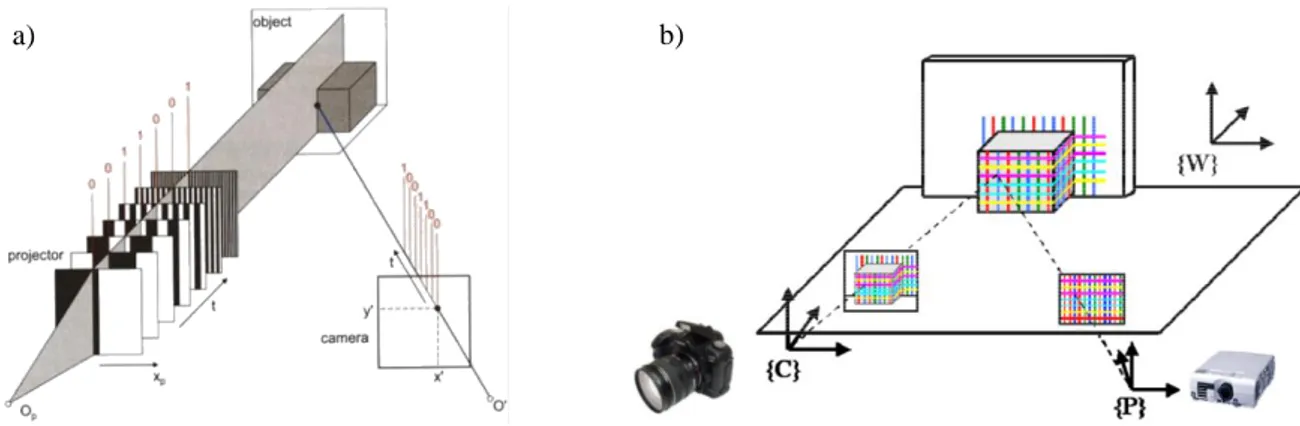
The projected patterns can be of different formats, for instance stationary and dynamic fringes, light sections or speckle patterns. Figure 2.8 depicts two different types of active triangulation systems.
Figure 2.8 (a) presents a fringe coded-light projection system, in which a sequence of n binary stripe patterns with 20 … 2n-1 vertical black and white stripes is projected onto the object surface, in order to assign a binary code to each pixel of the CCD camera. In figure 2.8 (b), a known pattern is projected
on the object surface. The pattern is collected by the camera and the point correspondences are found by matching the collected pattern with the reference pattern in the image, in order to recover the object surface based on the disparity measurements.
Figure 2.8 – Active triangulation systems based on: a) fringe coded-light projection (from Luhmann et al.
(2014)); b) structured light pattern (from Remondino (2010)).
2.1.2.3. Low-Cost Consumer-Grade Range Cameras Based on Active Triangulation and TOF Principles
Range cameras have been employed by the gaming industry for several years in order to provide controllers based on the human gesture and natural user interactions. Companies such as 3DV System Ltd. (Yahav et al., 2007) and Optrima NV (Van Nieuwenhove, 2011) provided range cameras for game consoles based on the TOF principle. PrimeSense, the previous market leading company (now a part of Apple Inc.) released range cameras originally applied to gaming, based on the active triangulation principle. The company is best known for providing the technology to Microsoft for producing the first Kinect, previously known as Project Natal. Figure 2.9 depicts the range cameras based on the PrimeSense technology; some of them were licensed to ASUS and Microsoft. The performance of some of these sensors (in terms of accuracy and repeatability) is analyzed and compared by Böhm (2014).
Although the range imaging devices and technology have been available for several years, interest in these sensors initially remained low; interest grew with the release of Microsoft Kinect. The most important reason was the mass production of Microsoft Kinect (24 million units were sold as of February 2013 (“Microsoft News,” 2013)), which had a great effect on the photogrammetric community in which the number of traditional 3D sensing systems such as laser scanners is in the range of 1000s. The low price of this system has made it one of the most affordable and accessible systems for the collection of 3D data. (Böhm, 2014; Luhmann et al., 2014)
Figure 2.9 – Range cameras based on the PrimeSense technology.
Top to bottom: Microsoft Kinect, PrimeSense PSDK, ASUS Xtion Pro Live and ASUS Xtion Pro. (from Böhm (2014))
a) b)
26 2. Overview of Indoor Data Collection Techniques
Microsoft Kinect for Xbox 360
The Microsoft Kinect was originally developed by the PrimeSense LTD as a human interface and a hands-free game controller for Microsoft Xbox 360 game console in November 2010. Releasing the non-official and later the official Software Development Kits (SDKs) for this device opened the way for a wide range of new activities in which range cameras play an important role, such as Augmented Reality, robotics (“MS Robotics Developer Studio,” 2014), security and surveillance (“Connecting Kinects for Group Surveillance,” 2014), medicine and surgery (“GestSure,” 2014; Loriggio, 2011), etc.
Reverse engineering has determined that this RGB-D sensor system consists of an IR laser projector, an IR camera (640×480 pixels resolution at 30fps, or 1280×1024 pixels at a lower frame rate with 11- bit depth), an RGB camera (640×480 pixels resolution at 30fps, or 1280×1024 pixels at a lower frame rate with 8-bit depth), a 3-axis accelerometer for recognizing the current orientation of the Kinect and a microphone array for capturing sound (see figure 2.10). The system has a 43° vertical by 57°
horizontal field of view, and performs within the range of 0.7-6m, providing centimeters accuracy in the range measurements.
The system projector emits a fix IR laser speckle pattern to the object surface (see figure 2.11 (a)). The pattern is then recorded by the IR camera which is located at a distance of about 7.5cm from the projector. The pattern consists of a 3×3 grid of light and dark speckles, with a significantly lighter speckle at the center of each grid (see figure 2.11 (b)). This special pattern design is used for the image matching technique performed by the Kinect (the algorithm is patented by PrimeSense and is not disclosed), in order to compute the disparity image by a comparison between the collected and the reference pattern. The disparity image is then converted to a point cloud using the SDKs and mathematical relationships mentioned in section 0. The accuracy analysis of the system range measurements is presented in section 6.1.2.
Figure 2.10 – Microsoft Kinect integrated sensors. (from (“MSDN Kinect,” 2015))
Figure 2.11 – Kinect IR laser speckle pattern projected on a real scene (left) and a flat surface (right).
a) b)
Microsoft Kinect V2 for Xbox One
Opposed to the mentioned sensor systems based on the PrimeSense technology, the Kinect V2 system is based on the time-of-flight principle. This system was released in November 2013 as a motion sensing input device for Xbox One, together with an SDK for software developers. The system uses the TOF technology and chips developed by Cantesa (Bamji et al., 2015) which was acquired by Microsoft before the release of the first Kinect sensor.
The system features an RGB camera with 1920×1080 pixels resolution at 30fps, an IR emitter and an IR sensor with 512×424 pixels resolution at 30fps (see figure 2.12). The pixels in the IR sensor are divided into a top and bottom half, each driven by separate clock drivers, working with tens of MHz frequency (Bamji et al., 2015), which means increasing the depth camera’s resolution to 1024×848 (“Doc-Ok.org,” 2015). The performance range of the system is 0.5-4.5m, with 70°H×60°V field of view. The accuracy of depth measurements by this system is within 2% across all lighting, color, users, and other conditions in the operating range (Sell and O’Connor, 2014).
The system costs around 150 Euros (non-official price in Germany, March 2015); the comparison between the resolution, accuracy and price of Kinect V2 with other TOF cameras such as SwissRanger 4000 or CamCube, which cost some thousands of Euros, is noticeable. Figure 2.13 depicts a sample point cloud collected by this system.
Figure 2.12 – Kinect V2 for Xbox One. (from (“iFixit,” 2013))
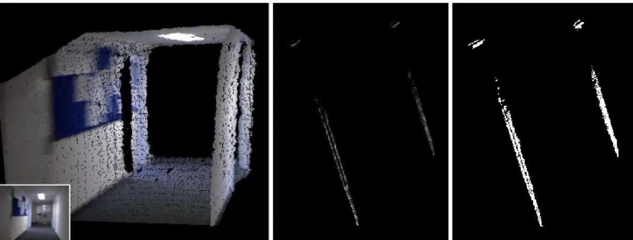
Figure 2.13 – A sample registered point cloud collected by Kinect V2 without noise removal.
RGB sensor IR sensor
IR emitter
28 2. Overview of Indoor Data Collection Techniques
2.1.2.4. Indoor Mobile Mapping Systems Based on Low-Cost Range Cameras
Inspired by Microsoft Kinect, and based on the PrimeSense active triangulation and state-of-the-art TOF technologies, low-cost commercial indoor mobile mapping systems are being developed increasingly. Examples of such systems are presented in the following parts.
DotProduct DPI-7 and DPI-8
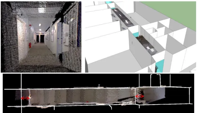
The DPI-7 handheld scanner is developed by DotProduct LLC, and uses a PrimeSense Carmine 1.08 RGB-D sensor for the collection of range images. According to “DPI-7 User Manual” (2014), the system integrates a 7” tablet as the user interface for the data collection as well as recording and processing the data. The integrated software automatically colorizes the point clouds, and performs the localization using the scene geometrical information (similar to KinectFusion (Newcombe et al., 2011)) for the alignment of the collected range images, with the ability to re-localize the sensor in case of losing the location track. Moreover, the software filters the noise of the point cloud and adjusts the color of the collected points which might be inconsistent due to the light conditions of the corresponding color images. The tablet is additionally used to give feedback to the user regarding the quality of the collected data and location tracking, indicated by augmented colors. Figure 2.14 depicts a sample point cloud collected by this system.
The successor of this system, DPI-8, uses an 8” NVIDIA SHIELD tablet with 2GB of RAM (twice the DPI-7), which results in a higher performance, as well as the ability of capturing rooms of at least 3 times the size. The nominal accuracy of the range measurements in both systems are the same (see table 2.4). In fact, due to the use of a similar sensor, the accuracy of the range measurements is similar to the accuracy measurements captured by Kinect. The system measures depths within the range of 0.6m - 3.3m; longer distances are filtered out in order to avoid the effect of noise in longer measurements. The DPI-8 system costs about 5800€ in Germany (May 2015).
Range Typical accuracy (RMS) Minimum accuracy
< 1m 0.2% 0.4%
1m - 2m 0.5% 0.8%
2m-3.3m 0.8% 1.2%
> 3.3m Not specified Not specified
Table 2.4 – Nominal accuracy of DPI-7 and DPI-8 range measurements.
Figure 2.14 – Left: DPI-7 system (adapted from “DotProduct LLC” (2015)); Right: a sample point cloud collected by this system (noise is already removed by the integrated software).
Structure Sensor
This sensor system is developed by Occipital, and captures the 3D map of indoor spaces using a range measurement system developed by PrimeSense (active triangulation) and an integrating iPad containing the software (figure 2.15 depicts the system). The software colorizes and aligns the range images captured from different viewpoints, and creates meshes. A notable feature of this system is the SDK provided for the developers in order to enable them to write mobile applications that interact with the 3D maps, Augmented Reality, measurements on the objects, gaming, etc. Some of the technical specifications of the system are summarized in Table 2.5. The range image alignment in this system is based on the observations in the 3D object space (similar to KinectFusion (Newcombe et al., 2011)); the sensor tracking is lost in case of dealing with flat surfaces.
Figure 2.15 – Structure Sensor mounted on an iPad. (from the company website) Field of view (H×V) 58°×45°
Measurement rate 30fps & 60fps Measurement range 0.4m - 3.5m
Precision 1% of the measured distance
Weight 99.2gr
Dimensions (W×D×H) [mm] 27.9×119.2×29
Price ($)* 379 and 499
Table 2.5 – Technical specifications of the Structure Sensor. *Official prices without iPad, in US, March 2015.
30 2. Overview of Indoor Data Collection Techniques
Google Project Tango
In recent years Google Inc. has shown increasing interest in indoor mapping and virtual reality.
Examples of the developed systems and applications are Google backpacker (the indoor version of the Google Street View cars), Google Art project (360 degree tours of art galleries using Street View indoor technology), Google Glass (for Augmented Reality and photography) and Google Project Tango.
The Google Project Tango is an Android device platform integrating depth sensors, advanced computer vision and image processing algorithms, developed in collaboration with currently 24 universities and industrial research labs for real-time 3D mapping of interiors (“Tango Concepts,”
2015) (see figure 2.16). The system range measurement is based on the TOF principle, using a PMD sensor developed by PMDTechnologies (2015). The sensor provides a quarter of a million of measurements every second (Say hello to Project Tango!, 2014), and works best within the range of 0.5m - 4m. The device collects range images while tracking its 3D motion using a wide-angle camera working based on visual-inertial odometry techniques, in order to create the 3D map of the environment (“Tango Concepts,” 2015).
The system costs around 1000$ (non-official price in US); currently, only a limited number of the prototypes of this product is available for researchers and software developers to develop applications and algorithms.
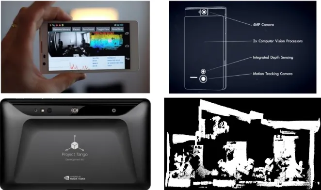
Figure 2.16 – Google Project Tango smartphone and tablet together with a sample collected data. (adapted from
“Google Store” (2015), “Say hello to Project Tango! ” (2014) and “The Verge” (2015))
2.2. The Registration Problem
Due to scene complexities and the scanners limited field of view, in many applications it is required to collect point clouds from multiple viewpoints in order to cover the whole scene. Point clouds collected from different viewpoints have their own local coordinate system; in order to align the coordinate systems, the corresponding point clouds have to be registered together using a rigid-body transformation, which is a special case of the 3D similarity (Helmert’s 7-parameters) transformation by setting the scale factor to 1. The transformation can be estimated using point correspondences in the point clouds, or by estimating the sensor pose in the reference coordinate system.
2.2.1. Registration Using Point Correspondences in the Point Clouds
The rigid-body transformation parameters can be estimated using point correspondences in the point clouds. In case the point correspondences are already given in the form of 3D features in the scene (artificial or natural) or 2D features in the corresponding intensity or color images, the transformation parameters can be estimated for instance using a closed-form solution based on the unit quaternions (Horn, 1987; Sanso, 1973). If the point correspondences are not provided, they can be estimated based on the geometrical structure of the scene, using an iterative procedure called Iterative Closest Point (ICP) algorithm (Besl and McKay, 1992). See appendix A for the mathematical background of the two approaches.
2.2.1.1. Correspondences by Recognition of 3D Features Artificial Targets
According to Luhmann et al. (2014), the most accurate way of registration is based on using artificial objects of known geometry in the scene, and spheres have proven to be the most reliable choice. The spheres in the scene are usually detected using the RANSAC algorithm, and their centers are used as tie points in the registration process (figure 2.17). More details about RANSAC algorithm is presented in appendix B.
Figure 2.17 – Fitting a sphere to a set of measured points.