Pyrolysis/Gasification
Status of Planning and Construction of Gasification Plants in the United Kingdom
Timothy Kast, Jim Starkey, Matthew Pierson and Michael L. Murphy
1. UK waste-to-energy market overview...367
2. Waste incineration directives...369
3. Gasification & process technology solutions ...370
4. Status of UK WtE gasification projects ...375
5. A look ahead ...377
6. Concluding remarks ...378
7. References ...378 As a result of its demographics and geography, the United Kingdom (UK) has relatively high waste disposal costs. Additionally, the government maintains various incentive programs to promote renewable, low-carbon energy generation and the use of advanced technologies, including gasification of biomass or waste, to meet the growing demand for electrical power. Consequently, it is currently one of the most active regions for waste-to-energy project development, especially when coupled with gasification.
However, new waste incineration plants are typically subject to stringent public poli- cies on their design and operation, such as the European Union’s Industrial Emissions Directive, making their development technically challenging. This paper describes how one company’s staged, fluidized bed gasification-combustion technology is especially qualified to meet the needs of this unique market and provides an overview of how it is being applied on several current projects. A status of project completion is also presented along with a look ahead to the future of waste-to-energy gasification in the United Kingdom and globally.
1. UK waste-to-energy market overview
It is estimated that over the next decade, Great Britain will require around a hundred billion GBP of capital investment in its electricity infrastructure to accommodate pro- jected future increases in electricity demand and to replace aging power stations. [10]
Additionally, the UK has committed to significantly increasing in the share of electricity generated by renewable sources. In 2010, it was projected that thirty percent of their electricity demand would need to be generated by renewable sources by 2020 in order
Pyrolysis/Gasification
increase the renewable portion of total energy demand from 1.5 % in 2005 to 15 %. [1]
To meet these targets, the government has passed legislation and established policies that require and incentivize investment in secure, low-carbon renewable electricity.
Accordingly, renewable energy project development has been very strong in the UK and should continue for the foreseeable future.
The two most noteworthy of these UK incentive programs are the Renewables Ob- ligation (RO) and the Contracts for Difference (CfD). RO was administered by the Office of Gas and Electricity Markets (OFGEM) and operated from 2002 until March of 2017. It required electricity suppliers to obtain a percentage of their electricity from specified renewable generation sources and provided incentives (called Renewable Obligation Certificates or ROC’s) to new renewable energy generators. ROC’s were available, without limit, to any applicant who met the program requirements. Biomass- or waste-to-energy (WtE) technologies were included in the RO program but gasifi- cation or pyrolysis of biomass or other wastes qualified for higher ROC’s per MWh.
The standard gasification/pyrolysis band was defined as producing a Synthesis Gas (Syngas) with a gross calorific value (GCV) of at least 2 MJ/Nm3 (25 °C and 0.1 MPa) while the advanced gasification/pyrolysis band required a GCV of at least 4 MJ/Nm3. With gasification qualifying for 1 to 2 ROC’s per MWh and the payout for 2015 to 2016 being 44.33 GBP/ROC, these incentives were significant. By the end of 2016, 25.5 GW of electricity was being generated by RO-accredited generating sources, including 5.0 GW from WtE. [11]
The UK Energy Act of 2013 and Energy Market Reform (EMR) policy established CfD as the successor program to RO for incentivizing low-carbon renewable energy gene- ration. [5] Rather than being an ‘all accepted’ program, developers must now compete for a fixed number of available long-term contracts at each auction. The program is intended to stabilize a renewable energy generator’s revenues by paying the difference between market electricity prices and a developers strike price bid that would make a project economically feasible. Should market prices exceed the strike price, the generator has to pay the difference back to the program administrator. WtE continues to be a qualifying technology for the CfD program and gasification of biomass or waste is once again eligible for higher target strike prices than standard WtE. OFGEM continues in a technology validation role. As would be expected, strike prices are falling such that the incentives are not currently as generous as those on the previous RO program.
However, these incentives remain a significant revenue source to developers.
There is no shortage of waste available for WtE projects in the UK. According to govern- ment statistics, the nation produced a total of 202.8 million tonnes in 2014 with 26.7 % of that ending up in landfills or being incinerated after all recycling or other final disposal methods, including existing WtE. [2] That same year, 2.43 million tonnes of waste was processed into refuse derived fuel (RDF) and shipped to mainland Europe for WtE use [3] and is increasing. [8] Assuming a 50 % yield of suitable RDF with an average GCV of 16 MJ/kg from the landfilled material and an overall WtE plant efficiency of 30 %, this represents approximately 4.5 GW of potential new renewable power generation.
Pyrolysis/Gasification
As an island nation with a population density nearly five times the world average [12], landfill tipping fees and taxes are relatively high in the UK. The average of 103 to 116 GBP/tonne [9] is more than 2.5 times the average in the United States [4], for example. The gate fee’s for accepting this material at WtE facilities is averaging 75 to 105 GBP/tonne [9] or approximately 18 % less than at landfills. These fees equate to approximately 90 GBP/MWh and, therefore, are a major factor in WtE project eco- nomic feasibility.
Finally, the relative costs of disposing of different solid residues is an important econo- mic factor to consider in WtE process development for the UK market. While fly ash from raw RDF or waste wood incineration can be disposed of in a standard landfill, typically at reduced fees or taxes [6, 7], or utilized for other beneficial purposes, ash that contains reagents from flue gas treatment (lime, hydrated lime or sodium bicar- bonate) is classified as a hazardous waste, requiring special disposal methods. As such, the cost to dispose of flue gas treatment residue can be significantly higher than the cost to dispose of raw fly ash (150 GBP/tonne versus 30 GBP/tonne was estimated for one project). Thus, minimization of flue gas treatment residue is an important design consideration for UK WtE projects.
2. Waste incineration directives
Beginning in the 1990’s, the UK established various regulations designed to ensure the safe and effective incineration of specific solid wastes or their co-incineration with other fuels. Municipal solid waste (MSW) or RDF, and class A to class C waste wood, which can come from construction or demolition sources, are among the types of waste covered by these regulations. Eventually, the European Community (EC) enacted a single Waste Incineration Directive (WID) (2000/76/EC), later incorporated into the broader EU Industrial Emissions Directive (IED) (2010/75/EU), which covered a range of industries. IED/WID is a comprehensive set of regulations designed to ensure that any plant that will thermally treat specific solid wastes will operate efficiently, utilize liberated energy effectively, limit solid & liquid residuals, and minimize emissions to the air, soil and water.
Each industry covered by IED has a separate collection of Best Available Techniques (BAT) to meet the goals of the directive called a BAT Reference (BREF) document, which is updated periodically. While a detailed review of BAT for waste incineration (WI) is beyond the scope of this paper, some key features associated with thermal oxidation include,
• employing effective combustor design and operating techniques;
• using flow modelling to ensure effective mixing and to demonstrate adequate residence time in the secondary combustion zone;
• maintaining flue gases above 850 °C with excess oxygen for a minimum of two seconds to ensure complete combustion; and
Pyrolysis/Gasification
• meeting specific maximum stack emission limits for key pollutants while striving to achieve even lower levels, if practical, by utilizing BAT technologies.
During the permitting process for any prospective WtE project in the UK, the Environ- ment Agency (EA) or Scottish Environment Protection Agency (SEPA) evaluates each proposal relative to BAT to ensure that the plant design and proposed operation will meet IED/WI. Therefore, the development of a waste-to-energy facility, particularly in Europe and the United Kingdom, requires comprehensive planning, analysis and scrutiny during the design phase.
3. Gasification & process technology solutions
The proprietary technology solutions offered by the Energy Products unit of Outotec (USA) Inc. (OEP) for the UK WtE market have been developed and refined over the last 40 years. The company began designing and manufacturing bubbling fluidized-bed solid waste-to-energy systems originally for the timber and wood products industries in the late 1970’s. The installation list includes 109 completed facilities ranging in size from 4 to 165 MWTh. These installations have employed a variety of fluidized-bed thermal oxidation arrangements, including combustors, air- and oxygen/steam-blown gasifiers, and staged gasification-combustion systems to produce hot gas, heated oil, combustible syngas, process steam, or electrical power. Waste fuels utilized include waste wood, MSW, RDF, agricultural residue, paper & sewage sludge, manure, tire derived fuel, animal rendering waste, and industrial & process wastes.
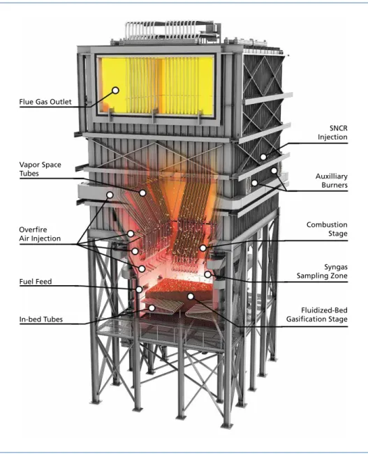
For the UK WtE market, OEP’s advanced staged gasification-combustion (ASGC) technology is particularly well suited to address the various market attributes and waste incineration directives described previously. A cutaway model of a typical ASGC reactor is shown in Figure 1. The ASGC system includes a bubbling fluidized-bed gasifier closely coupled to a gas-phase syngas combustor and furnace. With no intermediate cooling, cleaning, or processing of the syngas stream, an increased percentage of fuel energy is captured, since the non-oxidized solid fuel, or char, and volatilized low boiling point organic tars that leave the bed are also oxidized in the combustion stage. However, the UK incentive programs require some method of demonstrating and documenting the energy density of the produced syngas acceptable to OFGEM. Continuous or periodic sampling and analysis of the gas is one way to meet this requirement. So the freeboard above the bed is extended in height for these UK projects to allow for syngas mixing and sampling prior to the combustion stage.
At the gasification stage, solid fuel is fed to an atmospheric bubbling fluidized bed where fluidizing air is fed from below. Instead of using an over-bed stoker, as is shown in Figure 1, a specially designed fuel feed auger was developed for use on these UK projects to introduce the fuel directly into the bed. This feature helps keep the fuel within the bed longer and eliminates the introduction of unnecessary overfire air, both of which improve the syngas energy density. Fluidized beds are a very effective method for thermally treating solid fuels due to, a) the highly mixed and uniform
Pyrolysis/Gasification
conditions within the bed; b) the completeness of combustion or gasification of the fuel – aided by the continual scrubbing of the fuel surface by bed media; and c) the ability to closely control the bed temperature. Nearly all of the fuel entering the bed is elutriated up into the combustion stage as either tar-laden syngas, char or fly ash.
Utilizing a unique and proprietary design, bed media is continuously drawn down in a uniform fashion, cleaned of non-combustible and non-fluidizable material (tramp), and reinjected back into the bed. There are no moving parts within this gasification zone making it very reliable.
Flue Gas Outlet
SNCR Injection
Auxilliary Burners
Combustion Stage
Syngas Sampling Zone
Fluidized-Bed Gasification Stage Vapor Space
Tubes
Overfire Air Injection
Fuel Feed
In-bed Tubes
Figure 1: Cutaway model of typical advanced staged gasification-combustion reactor
Pyrolysis/Gasification
When operating as a gasifier, the conditions within the bed are maintained at sub- stoichiometric oxygen levels resulting in a controlled amount of fuel oxidation, or com- bustion. The heat generated by this partial combustion results in the volatilization and gasification of the remainder of the fuel to produce a syngas that can qualify for OFGEM’s standard gasification incentive band. Additionally, the bed is significantly smaller than a conventional fluidized bed combustor with an equivalent fuel throughput, so parasitic fluidizing fan power is also reduced.
As the syngas leaves the bed and flows upward into the combustion zone, secondary combustion air is added via successive horizontal rows of overfire air (OFA) nozzles.
Through this staged combustion approach, the oxygen equivalency in the bulk gas stream increases in a controlled fashion up to the final excess air level in order to manage the gas temperature profile and reduce the production of oxides of nitrogen (NOx). Combustion of the syngas, condensable hydrocarbons and any remaining or entrained solid fuel takes place in this region and provides additional heat energy, raising the temperature of the flue gas. The controlled, final flue gas temperature is selected to optimize the combination of, a) combustion; b) ash fouling and slagging behavior; c) performance of the Selective Non-Catalytic Reduction (SNCR) system for NOx control; and d) waste heat boiler per- formance. NOx emissions are controlled at the upper region of the combustion chamber (furnace) where a series of lances inject aqueous ammonia or a urea-water solution into the flue gas. Within this SNCR zone, the flue gas temperature is maintained within a suitable range for the reduction reactions to occur. These reactions take place within the upper vapor space of the furnace, the transition duct to the boiler, and within the initial gas pass of the boiler before the gas temperature drops below suitable levels.
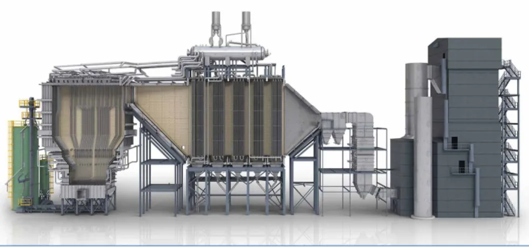
Within OEP’s ASGC reactor, steam generating water tubes are typically installed to extract heat from the bed, the furnace, or both, depending on each project’s specific characteristics, to improve overall boiler efficiency. Examples of these tubes are shown in Figure 1 and Figure 2. The furnace, or vapor tubes are installed in vertical rows near the refractory walls. Given some of the specific design criteria to meet OFGEM requirements for syngas calorific value, in-bed tubes are not utilized on these UK projects.
Figure 2: Simplified cutaway model of typical ASGC WtE plant arrangement
Pyrolysis/Gasification
All of the flue gas leaves the reactor furnace and flows to a modular, steam-generating, waste heat boiler through a transition duct, as illustrated in Figure 2. The boiler is made up of water/steam filled tubes arranged in successive evaporative or superheat tube bundles to produce the final superheated steam required by the process or turbine generator. With RDF or demolition waste fuels, consideration must be given to the boiler design to address the potential for fouling and high temperature corrosion. First, to reduce tube wall temperatures and flue gas to tube wall temperature differentials where tube wall temperatures are most elevated, several techniques are employed: the design steam condi- tions are typically limited to 45 bar(a) and 400 °C, an evaporative screen section is placed first in the flue gas path to reduce the flue gas temperatures into the superheater, and parallel- flow is typically used in the superheater. To limit bridging and tube surface ash fouling, which participates in the high temperature corrosion mechanism, gas velocities are reduced, tube spacing is increased, and proven ash or soot cleaning techniques are applied. Finally, corrosion-resistant alloy tubes may be used in the more vulnerable sections of the boiler.
720 700 740 760 780 800 820 840 860 880 900 920 940 960 980 1,000 1,020 1,040 1,060 1,080 1,100 1,120 1,140 1,160 1,180 1,200 (6) Temperature
°C
0 0.0005 0.0010 0.0015 0.0020 0.0025 0.0030 0.0035 0.0040 0.0045 0.0050 0.0055 0.0060 0.0065 0.0070 0.0075 0.0080 0.0085 0.0090 0.01 (7) Scalar variable
Figure 3: Example CFD temperature profile
Figure 4: Example CFD transient tracer profile
Many of the features of the combined ASGC and waste heat boiler represent IED BAT for effective, efficient and low-emissions combustion. To meet additional IED requi- rements, the overfire air (OFA) injection sys- tem and furnace are modelled using compu- tational fluid dynamics (CFD) to optimize their design and to validate residence time.
Figure 3 shows a sample planar temperature profile from one current UK project. It high- lights the effective mixing within the vessel, evidenced by the uniform temperatures abo- ve the last OFA level. And to demonstrate the IED system residence time, transient tra- cer studies are performed to predict tracer concentrations at the outlet of the qualifying secondary combustion zone over time.
One example planar concentration profile from another current UK project is shown in Figure 4, shortly after the injected tracer pul- se at the entrance of the qualifying zone. Last- ly, auxiliary burners (identified in Figure 1 and Figure 5) are installed in the reactor and are automatically started up any time the flue gas temperature in this zone might fall below 850 °C.
Pyrolysis/Gasification
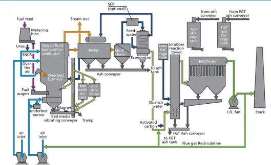
Figure 5: Typical OEP WtE gasification process flowsheet
The flowsheet shown in Figure 5 provides additional details of the complete WtE process, including the flue gas path downstream of the boiler and through the stack. A multi- cyclone unit is located immediately after the boiler to collect a significant portion of the total entrained fly ash. This unit serves two important purposes. First, it reduces the dust loading that enters the remaining downstream equipment. Second, and as noted earlier, the difference in disposal costs between raw fly ash and after reagents have been added in the back-end flue gas treatment (FGT) subsystem is significant.
Thus, removing as much ash as practical prior to the FGT system reduces the project operating expenses considerably. This justifies the separate ash collection and storage systems included in the flowsheet. The removal of a significant portion of the ash from the flue gas coupled with the flue gas temperature at the boiler exit (290 to 370 °C) also allows for the option to incorporate a selective catalytic reduction (SCR) unit for additional NOx and ammonia (NH3) abatement. Locating the SCR between the boiler and economizer, where the flue gas temperature remains suitable for SCR reaction thermodynamics and kinetics, eliminates the need for reheating.
The selected FGT subsystem addresses a range of IED BAT recommendations for the control of stack emissions. It typically includes a scrubber reaction tower for acid gas removal, including oxides of sulfur (SOx) and halogen halides (HCl, HF & HBr), using lime or hydrated lime as a reagent, followed by a baghouse (fabric filter) for dust control.
powdered activated carbon (PAC) can also be injected to aid in heavy metals removal and to absorb any remaining dioxins or furans that may have reformed downstream of the boiler through de-novo synthesis. With most FGT systems, ash and unused reagents are continuously recirculated from the fabric filter to the reaction tower to increase acid gas removal efficiencies and to reduce reagent consumption and solid residue.
Fuel feed Metering bins Urea
SNCR Over- fireair
augersFuel
inletair air inlet
Magnet Bed media vibrating conveyor underbed
burner
Tramp Overbed
burners Bed media
sto- rage
Boiler Steam out
Feed- water
Multi- clone
Lime ragesto- tank
Scrubber reaction tower
Ashsto- ragetank
FGT ashsto- rage tank
Baghouse
I.D. fan
Flue gas Recirculation FGT Ash conveyor to FGT
ash tank
Stack from ash
conveyor from FGT ash conveyor
Staged fluid bed gasifier- combustor
Activated carbon SCR
(optional)
Quench water Ash conveyor
Economizer to ash tank
Lime- stone Storage
Pyrolysis/Gasification
To increase overall plant efficiency and control odor, combustion air can be drawn from any facility building encompassing the boiler or fuel processing equipment and/or can be combined with recirculated flue gas (FGR). Using FGR in the fluidizing air fed to the gasifier is an effective means for regulating oxygen concentration in the bed while maintaining fluidizing characteristics across a defined firing range.
Together, the ASGC reactor and overall process developed for the UK WtE market repre- sents an advanced conversion technology solution that effectively addresses the policies, directives, economic objectives and technical challenges associated with this market.
4. Status of UK WtE gasification projects
Since 2015, a total of seven contracts have been awarded for the supply of the ASGC technology for UK WtE projects. All of these current projects are participating in either the OFGEM RO or CfD program. The approximate locations of the facilities are shown in Figure 6 and key project features are provided in Table 1. Together, these projects will produce approximately 95 MW of low-carbon renewable electrical power.
Figure 6:
UK WtE gasification project locations
Most of the ASGC projects are at a similar stage of completion due, in part, to the March 2018 deadline stipulated by the OFGEM RO or CfD programs. At the time of this writing, engineering and equipment delivery has been completed and substan- tial progress has been made on the construction of each. Photographs showing the
Pyrolysis/Gasification
current state of construction on some of these projects as of July of 2017 are provided in Figure 7. At present, all are scheduled to be completed and commissioned between the last quarter of 2017 and the first quarter of 2018.
Location Approx. size
Fuel Product
MWTh MWE
Upper Halliford,
England 16 4.5 RDF Electrical power
Forth, Scotland 46 12 RDF Electrical power Ince, England 89 22 Waste wood Electrical power Hull, England 99 25 RDF Electrical power Hull, England 41 10 Waste wood or RDF Electrical power Boston, England 41 10 Waste wood or RDF Electrical power Barry, Wales 41 10 Waste wood or RDF Electrical power
Table 1:
UK WtE gasification project details
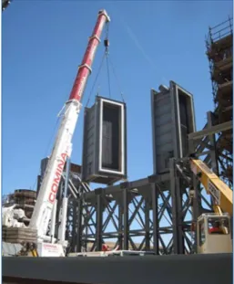
Figure 7: UK WtE gasification project construction status (July 2017)
Figure 8: Typical ASGC reactor panel assemby
Pyrolysis/Gasification
Site construction of these projects is greatly simplified by the widespread use of modu- larization and pre-fabrication. The ASGC reactor and most refractory lined ducts are delivered as pre-assembled panels, or sections, which include all of the internal insulation and refractory. These panels are then assembled on site (Figure 8).
In addition, most major equipment is pre-fabricated into larger, transportable modules. For example, each boiler mo- dule is almost fully assembled, including piping, headers and refractory, and is placed onto the supporting structure at the site (Figure 9).
Once completed and commissioned, the Outotec services group will be serving as the operations & maintenance (O&M) contractor for four of these facilities.
The advantages of this arrangement include early stage input to the design team on issues related to potential O&M improvements and a more direct relationship with the OEM technology supplier over the life of the plant.
5. A look ahead
The driving forces behind the WtE market in the UK show no signs of subsiding in the near term, so new project development continues. Incentives remain in place through the CfD program and tipping fees remain a significant source of revenue. Some developers are evaluating the viability of certain WtE projects without incentives.
Even as the market continues to advance, the regulations and directives associated with waste incineration will remain or become more stringent over time, requiring continual innovation.
Presently, there are numerous active projects at varying stages of development in the UK that have either committed to, or are evaluating the use of, the Advanced Staged Gasification-Combustion technology described in this paper. What’s more, similar projects are being developed outside of the UK in a variety of regions with diverse market influences. Thus, many of the characteristics of the UK WtE market are beco- ming important elsewhere as countries look to utilize unused waste resources to meet expanding energy demands with a low-carbon impact. The ASGC technology remains a viable solution in those regions, as well. And, as is the case for some current UK projects, Outotec may also provide long-term plant O&M services.
Figure 9: Typical modular boiler assembly
Pyrolysis/Gasification
6. Concluding remarks
The advanced staged gasification-combustion system and associated process equipment have been shown to be very compatible with the special attributes of the waste-to-energy market in the United Kingdom and globally, as evidenced by the seven projects currently being constructed and others being developed. With careful planning, analysis and design, these facilities can help meet critical energy needs in a profitable and low-impact manner; not only in the UK, but wherever there is a desire to minimize waste disposal and utilize low-carbon renewable energy. And the technology presented herein, while reflecting a history of over forty years, continues to progress. Implementation of new energy design features, emission control technologies, and execution efficiencies will allow this technology to remain at the forefront of advanced waste-to-energy techno- logy and to meet the growing demand and evolving requirements of this marketplace in the future.
7. References
[1] Department of Energy & Climate Change (DECC): National Renewable Energy Action Plan for the United Kingdom 2010. https://www.gov.uk/government/publications/national-renewable- energy-action-plan
[2] Department for Environment, Food & Rural Affairs (Defra): December 2016 Update. https://
www.gov.uk/government/statistics/uk-waste-data
[3] Environment Agency: Waste Data Interogator. https://data.gov.uk/dataset/waste-data-interro- gator-2014
[4] http://www.cleanenergyprojects.com/Landfill-Tipping-Fees-in-USA-2013.html
[5] https://www.gov.uk/government/collections/electricity-market-reform-contracts-for-diffe- rence
[6] https://www.gov.uk/government/publications/excise-notice-lft1-a-general-guide-to-landfill- tax/excise-notice-lft1-a-general-guide-to-landfill-tax
[7] https://www.gov.uk/government/publications/rates-and-allowances-landfill-tax/landfill-tax- rates-from-1-april-2013
[8] http://www.letsrecycle.com/news/latest-news/rdf-exports-three-million-tonnes-2016/
[9] http://www.letsrecycle.com/prices/efw-landfill-rdf-2/
[10] OFGEM: Energy Market Reform. https://www.ofgem.gov.uk/electricity/wholesale-market/
market-efficiency-review-and-reform/electricity-market-reform-emr
[11] OFGEM: Renewables Obligation Annual Report 2015-2016. https://www.ofgem.gov.uk/system/
files/docs/2017/03/ro_annual_report_2015-16.pdf
[12] United Nations: Population Division. https://esa.un.org/unpd/wpp/DataQuery/
Bibliografische Information der Deutschen Nationalbibliothek Die Deutsche Nationalbibliothek verzeichnet diese Publikation in der Deutschen Nationalbibliografie; detaillierte bibliografische Daten sind im Internet über http://dnb.dnb.de abrufbar
Thomé-Kozmiensky, K. J.; Thiel, S.; Thomé-Kozmiensky, E.;
Winter, F.; Juchelková, D. (Eds.): Waste Management, Volume 7 – Waste-to-Energy – ISBN 978-3-944310-37-4 TK Verlag Karl Thomé-Kozmiensky
Copyright: Elisabeth Thomé-Kozmiensky, M.Sc., Dr.-Ing. Stephanie Thiel All rights reserved
Publisher: TK Verlag Karl Thomé-Kozmiensky • Neuruppin 2017
Editorial office: Dr.-Ing. Stephanie Thiel, Elisabeth Thomé-Kozmiensky, M. Sc.
Janin Burbott-Seidel and Claudia Naumann-Deppe
Layout: Sandra Peters, Anne Kuhlo, Ginette Teske, Claudia Naumann-Deppe, Janin Burbott-Seidel, Gabi Spiegel and Cordula Müller
Printing: Universal Medien GmbH, Munich
This work is protected by copyright. The rights founded by this, particularly those of translation, reprinting, lecturing, extraction of illustrations and tables, broadcasting, micro- filming or reproduction by other means and storing in a retrieval system, remain reserved, even for exploitation only of excerpts. Reproduction of this work or of part of this work, also in individual cases, is only permissible within the limits of the legal provisions of the copyright law of the Federal Republic of Germany from 9 September 1965 in the currently valid revision. There is a fundamental duty to pay for this. Infringements are subject to the penal provisions of the copyright law.
The repeating of commonly used names, trade names, goods descriptions etc. in this work does not permit, even without specific mention, the assumption that such names are to be considered free under the terms of the law concerning goods descriptions and trade mark protection and can thus be used by anyone.
Should reference be made in this work, directly or indirectly, to laws, regulations or guide- lines, e.g. DIN, VDI, VDE, VGB, or these are quoted from, then the publisher cannot ac- cept any guarantee for correctness, completeness or currency. It is recommended to refer to the complete regulations or guidelines in their currently valid versions if required for ones own work.