TK Verlag Karl Thomé-Kozmiensky
Dorfstraße 51
D-16816 Nietwerder-Neuruppin
Tel. +49.3391-45.45-0 • Fax +49.3391-45.45-10 E-Mail: tkverlag@vivis.de
Waste Management
Waste Management, Volume 1 • Waste Management, Volume 2 • CD Waste Management, Volume 2 Waste Management, Volume 3 • CD Waste Management, Volume 3 • Waste Management, Volume 4
160.00 EUR
save 111.00 EUR
Package Price
Waste Management, Volume 1 Publisher: Karl J. Thomé-Kozmiensky,
Luciano Pelloni ISBN: 978-3-935317-48-1 Published: 2010 Hardcover: 623 pages Language: English, Polish and German Price: 21.00 EUR
Waste Management, Volume 2 Publisher: Karl J. Thomé-Kozmiensky,
Luciano Pelloni ISBN: 978-3-935317-69-6 Published: 2011 Hardcover: 866 pages,
numerous coloured images Language: English
Price: 50.00 EUR CD Waste Management, Volume 2 Language: English, Polish
and German
ISBN: 978-3-935317-70-2 Price: 50.00 EUR
Waste Management, Volume 3 Publisher: Karl J. Thomé-Kozmiensky,
Stephanie Thiel ISBN: 978-3-935317-83-2 Published: 2012 Hardcover: 744 pages,
numerous coloured images Language: English
Price: 50.00 EUR CD Waste Management, Volume 3 Language: English
ISBN: 978-3-935317-84-9 Price: 50.00 EUR
Waste Management, Volume 4 Publisher: Karl J. Thomé-Kozmiensky,
Stephanie Thiel ISBN: 978-3-944310-15-2 Published: 2014 Hardcover: 521 pages,
numerous coloured images Language: English
Price: 50.00 EUR
Order your book on www. .de
or
Karl J. Thomé-Kozmiensky
WASTE MANAGEMENT
Luciano Pelloni
Thomé-Kozmiensky und PelloniWASTE MANAGEMENT
Volume 1 Eastern European Countries Karl J. Thomé-Kozmiensky
Volume 2
WASTE MANAGEMENT
Luciano Pelloni
Waste Management Recycling Composting Fermentation Mechanical-Biological Treatment Energy Recovery from Waste Sewage Sludge Treatment
Thomé-Kozmiensky und PelloniWASTE MANAGEMENT
2
Thomé-Kozmiensky und Pelloni
Karl J. Thomé-Kozmiensky
Volume 3 Recycling and Recovery
WASTE MANAGEMENT
Stephanie Thiel
WASTE MANAGEMENTThomé-Kozmiensky und Thiel
3
2
1
WASTE MANAGEMENT Volume 3
KARL J. THOMÉ-KOZMIENSKY STEPHANIE THIEL HRSG.
Copyright © 2011 TK Verlag Karl Thomé-Kozmiensky Alle Rechte vorbehalten.
Das Einspeisen der Daten in Netzwerke ist untersagt.
, Thiel WASTE MANAGEMENT
Volume 3
KARL J. THOMÉ-KOZMIENSKY STEPHANIE THIEL HRSG.
Copyright © 2012 TK Verlag Karl Thomé-Kozmiensky Alle Rechte vorbehalten.
Das Einspeisen der Daten in Netzwerke ist untersagt.
Pyrolysis/Gasification
Pyrolysis and Gasification – State of the Art
Peter Quicker
1. Thermal processes for waste treatment ...416
1.1. Overview and classification of thermochemical processes ...416
1.2. Classic alternative methods for waste treatment ...417
1.2.1. Pyrolysis ...418
1.2.2. Gasification ...420
1.3. Recent developments ...422
1.3.1. Plasma processes ...422
1.3.2. Liquefaction of waste ...424
1.3.3. Hydrothermal processes ...425
2. Application of thermal processes for waste treatment ...427
2.1. Pyrolysis ...427
2.2. Gasification ...429
2.3. Plasma processes ...431
2.4. Liquefaction processes ...432
3. Conclusion ...433
4. Literature ...434 Considering the worldwide number of installations as well as their capacity, the most dominating treatment method for waste is incineration. Currently, 225 million tons of waste are treated in 2,200 facilities [9].
Besides this established and – concerning oxygen input – overall hyperstoichiometric treatment method (excess air conditions), the substoichiometric processes pyrolysis and gasification are also found in the market. These so-called alternative methods have been presented by different providers under varying names ever since the 1970ies. Their characteristic lies in comparably complex systems engineering and process equipment.
According to suppliers, the advantage of substoichiometric processes lies in higher electrical efficiency and/or a higher quality of conversion products, for example vitrified slag of low leachability or non-fossil liquid fuels.
While alternative processes have gained no relevance in Germany due to experiences marked by setbacks, discussion abroad has intensified in recent times and some lobby groups and decision makers explicitly claim the use of these technologies for waste
Pyrolysis/Gasification
treatment. Supporters point out successful long-time operation of facilities in Asia, especially in Japan. Yet it must be considered that the general framework and waste treat- ment policy in this region differs significantly from that in Europe or North America.
Practical experiences mentioned above mainly refer to gasification and pyrolysis plants.
Besides these classic thermochemical processes, other alternative processes have entered the market in the last few years.
Plasma processes (implemented as plasma gasification) convert waste respectively py- rolysis char by contact with plasma (partly ionized gas) with a temperature of at least 2,000 °C. According to providers of this technology, this leads to low gaseous emissions and, at the same time, high quality conversion residue.
Another alternative thermochemical process type is the catalytic direct liquefaction pro- cess. In this process – also sometimes referred to as oilization – solid waste is converted into liquid carbohydrates in a single-stage process often using catalysts. The intention is to generate products with fuel-like properties that could be used to substitute diesel.
The so-called HTC processes (hydrothermal carbonization) are preferably applied for (wet) organic waste and (sewage) sludge. Waste material in a fluid aqueous phase is converted to a carbonization product that is meant to allow improved energetic or material utilization.
Both plasma processes and liquefaction are currently subject of intense discussion, hydrothermal carbonization is about to be launched on the market. Yet, there is little reliable operating experience documented for all three processes. What is more, in some cases even plausible mass and energy balances are not available. Treatment of proble- matic secondary and minor material flows is often only laid out on conceptual level.
1. Thermal processes for waste treatment
The following section describes the basic principles of thermochemical conversion processes underlying those waste treatment processes discussed in this article, starting with an overview and a classification of processes for the treatment of waste.
1.1. Overview and classification of thermochemical processes
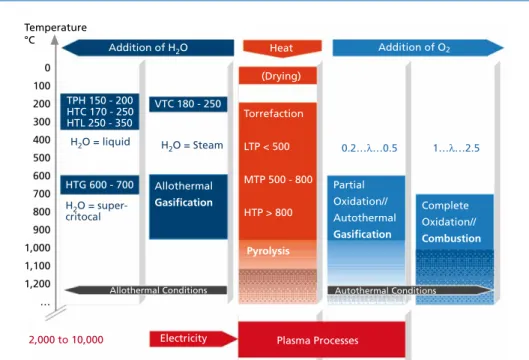
As shown in Figure 1, basic thermochemical processes can be classified regarding heat supply and reactant, distinguishing between
• Processes with external heat supply (pyrolysis),
• Processes with oxygen as reactant (autothermal gasification and combustion),
• Processes with water as reactant (allothermal water-steam gasification, hydrother- mal processes),
• Processes in which a partly ionized gas of high temperature is generated by applying electrical voltage (plasma processes).
Pyrolysis/Gasification Figure 1: Overview of thermochemical processes
The following chapters give further information on the processes introduced above.
1.2. Classic alternative methods for waste treatment
homogenous gasification reactions
homogeneous water-gas reaction: CO + H2O CO2 + H2 methane formation: CO + 3 H2 CH4 + H2O carbon monoxide oxidation: CO + 1/2 O2 CO2 hydrogen oxidation: H2 + 1/2 O2 H2O
gasification agents O2 (air), H2O, (CO2)
product gas H2, CO, CH4, CO2, H2O, N2 (air gasification) tars
gasifier coke minerality and residual carbon heterogeneous
gasification reaction
heterogeneous water gas reaction: C + H2O CO + H2 Boudouard-reaction: C + CO2 2 CO complete combustion: C + O2 CO2 incomplete combustion: C + 1/2 O2 CO hydrating gasification: C + 2 H2 CH4 drying
and pyrolysis heat
pyrolysis gases
H2, CO, CO2, CH4, C2H6, C2H4 steam, organic compounds containing O2,
higher hydrocarbon (tars)
fuel
Figure 2: Pyrolysis and gasification in a simplified overview (heteroatoms are not considered)
0 100 200 300 400 500 600 700 800 900 1,000 1,100 1,200
…
Addition of H2O
TPH 150 - 200 HTC 170 - 250 HTL 250 - 350
VTC 180 - 250
HTG 600 - 700
H2O = liquid H2O = Steam
Heat (Drying)
Torrefaction LTP < 500 MTP 500 - 800 HTP > 800
Pyrolysis
Addition of O2
Allothermal Gasification H2O = super-
critocal
Partial Oxidation//
Autothermal Gasification
Complete Oxidation//
Combustion
Electricity Plasma Processes
Allothermal Conditions Autothermal Conditions
0.2…λ…0.5 1…λ…2.5
2,000 to 10,000
Pyrolysis: LTP = Low Temperature Pyrolysis, MTP = Middle Temperature Pyrolysis, HTP = High Temperature Pyrolysis Hydrothermal processes: TPH = Thermal Pressure Hydrolysis, HTC = Hydrothermal Carbonization,
VTC = Vapothermal Carbonization, HTL = Hydrothermal Liquefaction, HTG = Hydrothermal Gasification Temperature
°C
Pyrolysis/Gasification
Both pyrolysis and gasification can be called classic alternative thermal waste treatment processes. Already by the end of the 19th century, gasification was tested in several Euro- pean cities in order to generate illuminating gas for street lighting. In San Jose, California, gasification gas was even used as motor fuel. Yet, all attempts had to be given up after a short time (high ash content, uneconomic operation, explosions) [7, 29].
The basic processes taking place during pyrolysis and gasification are shown schematically in Figure 2. In particular, the most important homogeneous and heterogeneous gasification reactions are shown.
1.2.1. Pyrolysis
The term pyrolysis refers to thermochemical decomposition of organic materials caused by external heat supply in the absence of either oxygen, other oxidizing agents or other reactants, whereas in practice introduction of small amounts of oxygen or air with input materials cannot be avoided. Depending on process temperature, the following distinction is drawn:
• Low temperature pyrolysis (LTP) T < 500 °C,
• Medium temperature pyrolysis (MTP) 500 °C < T < 800 °C,
• High temperature pyrolysis (HTP) T > 800 °C.
1 10
1,000
500 Temperature
°C
0.1
Gas Pyrolysis Oil
0
Heat supply
> 106 W/m2 > 105 W/m2 > 104 W/m2 < 103 W/m2
Coal
> 1,000 Residence Time Gas s
Recently, pyrolysis at temperatures between 250 and 300 °C is referred to as torrefaction.
This low-temperature type of pyrolysis is traditionally applied in processing and refining of food and is currently discussed and tested as a means to customize biomass fuels, especially to raise calorific value and optimize physical properties (grindability, hydrophobicity).
Another criterion to differentiate pyrolysis processes can be (gas-)residence time.
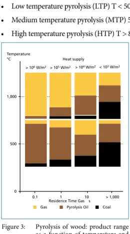
When input materials go through a rapid heating phase, the process is called flash- pyrolysis. This way a high yield of liquid products can be achieved especially at low temperatures. Higher process temperatures lead to more gaseous components in the product range. Calorific values decrease with increasing temperature [39]. The ad- jacent figure schematically demonstrates the interrelation between temperature, resi- dence time and expected product range for the example of wood [12]. Results can differ significantly for waste (especially waste with low cellulose content).
Figure 3: Pyrolysis of wood: product range as a function of temperature and residence time (schematically)
Source: Gerdes, C.: Pyrolyse von Biomasse-Abfall: Thermo- chem sche Konversion mit dem Hamburger-Wirbelschichtver- fahren Dissertation, Universität Hamburg 2001; translated
Pyrolysis/Gasification
Torrefaction as well as flash pyrolysis are used to refine biomass. These processes are not relevant for the treatment of municipal solid waste and are therefore not discussed any further in this article.
For thermal treatment of waste, intermediate and slow rate pyrolysis methods in the medium and high temperature range are relevant. Products expelled under these con- ditions are mainly gaseous. Yet with sufficiently long residence time, aromatization and polymerization may lead to (re-)composition of liquid or solid reaction products.
The gas mainly consists of CO2, CO, hydrogen, methane, ethane and ethene. Product properties are determined by waste composition. For example, different dominating plastic fractions in the input material cause a significantly altered composition of pro- duct gas. Another important factor influencing the product range of pyrolysis is the water content of input waste, because higher humidity leads to increasing relevance of the heterogeneous and homogeneous water-gas reaction (Figure 2) [39].
The amount of hydrogen and carbon monoxide in the gas increases with temperature, while the concentration of carbon dioxide, methane and higher alkanes recedes [1, 35, 36]. The mass fraction of condensable products decreases with temperature as well.
However, due to the high calorific value of contained tars, the aqueous phase still holds a significant energy content.
100 60 40 32
weight %
0 250 370 850
temperature °C
H H
H H H
HH H
H
HH H cellulose
split-off
oxygen elimination - OH and
- CH2OH
split-off hydrogen formation of
CO2, CO, H2O
Figure 4: Processes and temperature dependancy of pyrolytic decomposition of cellulose
Source: Thomé-Kozmiensky, K.-J. (ed.): Thermische Abfallbehandlung, EF-Verlag, Berlin, 1994; modified
Using the example of cellulose, the diagram (Figure 4) shows the processes during degassing as well as generated products, the conversion of the material structure and mass loss of solid material as a function of temperature.
Pyrolysis/Gasification
Residual coke mainly consists of carbon and inert materials contained in the feed material (mineral and metal components). Non-volatile heavy metals also remain in the coke fraction [34]. Heavy metals with higher volatility like mercury, cadmium and lead and their chlorides and oxides are already transferred to the gaseous phase at moderate temperatures [8]. At low temperatures, these heavy metals are partly bound to the coke fraction as metal sulfides.
Sulfur contained in the processed waste is transferred to the gaseous phase as hydrogen sulfide and eventually as carbonyl sulfide. A significant amount of sulfur remains within the solid coke residue fraction [35, 31].
Nitrogen compounds in the waste are decomposed during pyrolysis and transferred to the gaseous phase as ammonia (NH3), hydrocyanic acid (HCN) and elementary nit- rogen. Secondary reactions especially of ammonia may occur. Little nitrogen remains in the coke [35].
Organically bound chloride, e.g. PVC, passes into the gas phase as HCl. Unlike in incineration processes, chloride bound in salt (NaCl) remains – at least at moderate temperature – in the solid residue [34]. Fluoride on the other hand is converted to gaseous HF [36].
Depending on the properties of input material, the calorific value of pyrolysis gases fluctuates in a wide range. When condensable compounds (pyrolysis oil vapors) are included, high calorific values between 12.5 and 46 MJ/m³N can be obtained. The ca- lorific value of non-condensable permanent gases lies between 12 and 16 MJ/m³N [37].
1.2.2. Gasification
Gasification processes aim to convert mostly solid, sometimes also liquid or pasty materials to a fuel or synthesis gas with the highest possible calorific value, hereby allowing improved utilization in comparison to the original solid material. The solid material is brought into contact with a reactive gasification agent which introduces oxygen or – in the case of water vapor as agent – hydrogen into the process. Possible gasification agents are
• Air,
• Oxygen,
• Water vapor,
• Carbon dioxide.
Gasification is defined as autothermal when the gasification agent causes partial oxidati- on of the fuel, as is the case when using oxygen or air as gasification agent. Therefore, the necessary heat of reaction for the mainly endothermic gasification reaction is generated by the fuel. Energy content of the gas is reduced accordingly (cold gas efficiency usually about 80 percent at most). The limitation of oxygen supply is crucial for gasification in order to prevent energy loss or complete oxidation of feedstock. Usual conditions imply an oxygen supply of 30 to 40 percent of the total oxygen demand, synonymously given as air ratio of 0.3 to 0.4.
Pyrolysis/Gasification
When hydrogen is used as gasification agent, there is no heat released since no partial oxidation of fuel occurs. On the contrary, additional thermal energy is needed since water molecules are split generating oxygen and hydrogen. This operation mode is called allothermal gasification since necessary energy is supplied by external sources (Greek:
állos = other, different). External heating on the outer surface of the reactor is usually not sufficient to maintain the gasification process. Therefore, several heating options are applied, e.g. hot sand (circulating bed), hot ceramic balls or heatable built-in components.
Thermochemical gasification involves a number of stages: drying, degassing (pyrolysis), homogeneous and heterogeneous gasification reactions. Figure 2 shows theses sequences schematically. In the heating phase, humidity is evaporated. First small amounts of carbon dioxide and carbonic acids occur already at temperatures below 200 °C. Degassing inten- sity of volatile components rises with temperature. Only after the main part of degassing is completed, gasification agents or process-generated gases (hydrogen, carbon monoxide) can be transported by diffusion or convection to the surface of the largely degassed solid material mainly consisting of fixed carbon. Then, the heterogeneous gasification reactions outlined in Figure 2 can take place.
The built gases react among themselves and with the used gasification agents. The most important homogeneous gasification reactions are also illustrated in Figure 2.
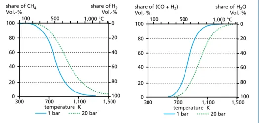
Product composition in gasification processes depends on both temperature and pressure.
Rising temperatures lead to an increase of carbon monoxide and hydrogen whereas methane content decreases. Increasing pressure on the other hand promotes generation of methane and carbon dioxide. [37] The influence of pressure and temperature on the heterogeneous water-gas-reaction and hydrating gasification is illustrated in Figure 5.
temperature K 100
80 60 40 20 share of CH4 Vol.-%
300 700
0
share of H2 Vol.-%
1,100 1,500 1 bar 20 bar
100 80 60 40 20 1,000 °C 0 500
100
temperature K 100
80 60 40 20
share of (CO + H2) Vol.-%
300 700
0
share of H2O Vol.-%
1,100 1,500 1 bar 20 bar
100 80 60 40 20 1,000 °C 0 500
100
Figure 5: Temperature and pressure dependency (examples for 1 and 20 bars) for hydrating gasification reaction (C + 2 H2n CH4, left) and heterogeneous water-gas-reaction (C + H2O n CO + H2, right)
adapted from: Kaltschmitt, M.; Hartmann, H.; Hofbauer, H.: Energie aus Biomasse – Grundlagen, Techniken, Verfahren 2. Auflage, Springer-Verlag, Berlin, Heidelberg, 2009
Pyrolysis/Gasification
Sulfur contained in the feedstock is mainly transferred to the gas phase as hydrogen sulfide. COS is hardly detected [15]. Nitrogen is detected as ammonia and small amounts of HCN. At typical gasification temperatures, most of the ammonia is converted to elementary nitrogen. Chlorine occurs as HCl [25].
Generated product gases are very much determined by the gasification agent, they have a lower calorific value than pyrolysis gases. Calorific values of more than 12 MJ/m³N are achieved with allothermal water-steam-gasification [37]. When oxygen is used as gasification agent, calorific values range from 10 to 18 MJ/m³N. The lowest calorific values are found in autothermal air gasification since the product gas is diluted the high inert nitrogen content of up to 60 percent. [41]
1.3. Recent developments
1.3.1. Plasma processesPrimarily developed for aerospace and military application, plasma processes are now used in metallurgy and waste treatment as well. Suitability of plasma processes for thermal waste treatment has been proved in the past for hazardous waste fractions like asbestos or chemicals. Vitrification of radioactive waste is another established application. Besides these treatment processes for mono-fraction wastes, plasma sup- ported thermal waste treatment processes for municipal waste have been introduced to the market in recent years and are now offered by suppliers all over the world. [10]
Classic alternative thermal processes generally obtain necessary temperatures by par- tial oxidation of fuel (direct heating) or by external heating of the reactor surface resp.
by using a heat transfer medium (indirect heating). Plasma generation is yet another example process for direct heat transfer. A process gas (either oxidizing or inert) is ionized, supplying a large specific amount of thermal, electric or electromagnetic energy. Considering the level of energy, plasma is also considered the fourth state of aggregation. [17]
Plasma is generated in plasma torches by applying a voltage between two electrodes causing an arc discharge. Plasma arc torches can be divided into non-transferred and transferred arc torches.
In transferred arc torches, the arc is generated between a free cathode and an external anode. Working gas flows around the rod-shaped cathode which is surrounded by a cooled circular shell. The arc caused by voltage between cathode and anode provides the necessary energy to generate plasma. The gas flow through the shell causes the heated gas to leave the lance as plasma jet [22]. Depending on design, the distance between cathode and anode may amount to one meter. Due to extremely elevated thermal flux, minerals and metals contained in the treated materials are liquefied and vitrified [4].
The melting bath is grounded electrically at the walls of the reactor. In transferred arc torches, the melting bath takes on the function of anode for the arc [14].
Pyrolysis/Gasification Figure 6: Plasma generation with non-transferred arc (left) and transferred arc (right)
Source: Bonizzoni, G.; Vasallo, E.: Plasma Physics and Technology Industrial Applications. Vacuum. 64. Jg. 2002, Nr. 3-4, pp.
327-336
When plasma is generated by a non-transferred arc, the electrodes are installed in a housing. In contrast to the transferred arc, in non-transferred arcs it is not the melted material that serves as anode but the burner lance itself. Just like in non-transferred arc torches, working gas flows around the rod-shaped cathode.
Plasmas generated for thermal waste treatment reach temperatures between 2,000 and 30,000 K [22].
One aspect mentioned as advantage of plasma processes is the comparatively easy temperature regulation with electrical power as control quantity [10]. In the case of plasma gasification, this allows decoupling of heat release and oxidizing agent supply.
Furthermore, plasma processes are characterized by high heat transfer to the treated substance, high heating rates in the starting-up phase and small size of installations.
Plasma treatment leads to decomposition of high-molecular compounds (tars etc.) which are generated in classical alternative thermal processes. Due to high process temperatures and depending on process design, it is even possible to melt temperature resistant process residues. [17]
When process energy is provided exclusively by plasma, this results in high energy costs.
Accordingly, most suppliers offer combined plasma processes. These include a classic pyrolysis respectively gasification step on a moderate temperature level combined with a downstream plasma step for gas treatment and/or vitrification of residue material.
Differentiating factors of the offered plasma conversion processes are therefore mainly the design of the low-temperature conversion step and plasma generation, and not the plasma conversion itself. [26]
Carrier gas Cathode _
Anode
Hot gas + Anode
Carrier gas Cathode _
Pyrolysis/Gasification
Just like classic alternative processes for thermal waste treatment, plasma processes are divided into pyrolysis and gasification processes. In plasma pyrolysis, inert gases like argon or nitrogen are utilized, whereas plasma gasification uses working gases containing oxygen. [16]
1.3.2. Liquefaction of waste
Liquefaction of waste or biomass aims to generate a fuel product in a direct process. The output is to be a product that is either conforming to fuel standards or an intermediate product comparable to crude oil or gas oil. Technologies applied to produce syngas with subsequent oil synthesis are not object of consideration at this point.
The possibility to liquefy waste fractions depends on their chemical composition. The target product consists of hydrocarbon chains, or simpler: (-CH2-)n. Input materials with a comparable structure are polyolefins. Other plastic fractions and biomass contain an increased share of heteroatoms (oxygen, nitrogen, sulphur, chloride) which either prevent direct formation of pure CH2-chains or significantly reduce the content of these chains in the product.
Polyolefins can be directly split thermally into short-chain paraffin waxes and olefins.
High temperatures (> 600 °C) and short residence time lead to a higher content of short chain hydrocarbons, whereas low temperatures (< 400 ° C) and longer residence time cause longer chains. Unless saturated with hydrogen, olefins tend to polymerize and therefore show low ageing stability. [11]
Reaction pathways for the decomposition of heteroatom rich input fractions like biomass are by far more complex. To produce high value oils, it is indispensable to widely eliminate heteroatoms. What is more, the hydrogen/carbon ratio in biomass is about 1.4 and is therefore significantly lower than the ratio of the target product (H/C ratio approximately 2). Conversion to hydrocarbon can take place in the presence of hydrogen or hydrogen transferring substances. Advanced technologies claim to achieve high quality products solely using a catalyst. So far, scientific proof of this fact has not been provided. [3]
When product oils shall be used as fuels, they must meet the specifications of respective standards. For diesel fuels, this is DIN EN 590, for petrol it is DIN EN 228.
Process approaches for liquefaction can be distinguished as follows:
• High pressure hydrogenation,
• Depolymerization,
• Solvolysis:
– Organic solvent,
– Water as solvent (hydrolysis),
• Combined processes.
All treatment principles operate with a liquid phase. This is to enhance miscibility and allow rapid heating of input materials.
Pyrolysis/Gasification
High pressure hydrogenation aims to generate saturated products with a low amount of heteroatoms. Pressure ranges from 100 to several hundred bar, temperatures are between 300 and 350 °C. The use of hydrogen as hydration agent leads to a comparatively high product quality at the price of high operating efforts.
Depolymerization is basically a thermal decomposition of the input material. A start- up oiladded in the start-up phase should not be converted within in the process. The process is operated at 250 to 420 °C slightly below atmospheric pressure. Liquefaction processes which are currently offered on the market operate based on the principle of depolymerization.
In solvolysis, a solvent takes part in the reaction. Used solvents are either organic com- pounds (e.g. oils, ethylene-glycol or water/phenol) and/or water with either acidic, basic or neutral pH value. In literature, temperatures from 300 to 450 °C and pressures up to 200 bar are given as reaction parameters. [3, 38]
1.3.3. Hydrothermal processes Hydrothermal carbonization was discovered by Bergius at the beginning of the 19th century [13]. The use of this technology for the purpose of waste treatment has only recently come into focus, going back to the work of Professor Antonietti at the Max- Planck-Institute of colloids and interfaces in Potsdam, Germany [30]. Based on his research, this topic is downright booming at the moment and many research institutions and companies are working on this field.
By hydrothermal carbonization, biogenic materials like plant residue, biodegradable waste or sewage sludge can be converted to a carbonization product (also called hydrochar) with both high carbon content and calorific value (Figure 7). Biomass is treated in an aqueous phase with a residence time of 2 to 16 hours at temperatures between 170 and 250 °C and a pressure sufficient to maintain a liquid state of aggregation (10 to 40 bars).
Citric acid is added frequently and usually denoted as catalyst.
Figure 7:
Hydrothermal carbonization;
left: starting material, right:
product
Source: Ramke, H.-G.: HTC-Biokohle aus organischen Abfällen Biokohle – Kli- maretter/Mogelpackung 72. Symposium des ANS, Berlin, 05.-06. October 2011
Besides the desired carbonization product, permanent gases (up to 5 to 10 wt percent) and wastewater (5 to 15 wt percent) occur. Exhaust air frequently contains significant amounts of hydrogen sulfide. Carbon monoxide, methane and further volatile hydro- carbons occur, requiring mandatory waste-air purification. [32]
Pyrolysis/Gasification
The wastewater pH shows acidic values (3.5 to 6.5) and is contaminated with high organic loads. Typical COD-values range from 30,000 to 100,000 mg/l. The COD/
BOD ratio is 2 to 2.5 indicating refractory, i.e. non-degradable COD which causes problems in wastewater purification. Also, nitrogen loads of up to 5,000 mg/l require further treatment. [32]
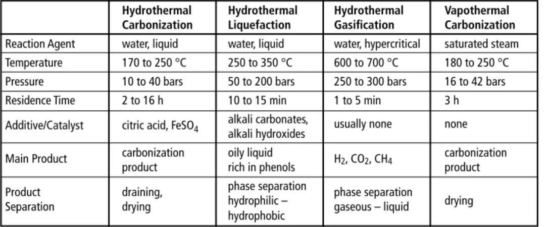
Besides hydrothermal carbonization, two other hydrothermal processes exist: hydro- thermal liquefaction and hydrothermal gasification. In contrast to hydrothermal car- bonization, these two processes aim to enrich carbon in a liquid or gaseous product usable as fuel. Typical process parameters of hydrothermal processes are given in table 1.
Table 1: Basic process parameters of hydrothermal processes
Hydrothermal Hydrothermal Hydrothermal Vapothermal Carbonization Liquefaction Gasification Carbonization Reaction Agent water, liquid water, liquid water, hypercritical saturated steam Temperature 170 to 250 °C 250 to 350 °C 600 to 700 °C 180 to 250 °C Pressure 10 to 40 bars 50 to 200 bars 250 to 300 bars 16 to 42 bars
Residence Time 2 to 16 h 10 to 15 min 1 to 5 min 3 h
Additive/Catalyst citric acid, FeSO4 alkali carbonates, usually none none alkali hydroxides
Main Product carbonization oily liquid H2, CO2, CH4 carbonization
product rich in phenols product
Product draining, phase separation phase separation
Separation drying hydrophilic – gaseous – liquid drying
hydrophobic
adapted and amended from:
Clemens, A.: Hydrothermale Carbonisierung – Konversionsprozess zur Bereitstellung von festbrennstoffen aus biogenen Reststoffen DBFZ-Fachgespräch Feste Biomasse, LeipziG, 12. Oktober 2011
Klemm, M.; Kaltschmitt, M.; Thrän, D.; Viehmann, C.: Hydrothermale Carbonisierung im Vergleich zu anderen Verfahren zur energetischen Nutzung nasser Biomasse Fachtagung Energie und Rohstoffe aus landwirtschaftlichen Reststoffen – Hydrothermale Carbonisierung ein geeignetes Verfahren? Johann Heinrich von Thünen-Institut (vTI), Berlin, 5.März 2009
N.N. Das VTC-Verfahren. EEK, Erdöl Erdgas Kohle, 127. Jg. 2011, Heft 12, p.477
Another technology to carbonize biomass currently in development is vapothermal carbonization (VTC). The main difference to HTC lies in the utilization of saturated steam instead of (liquid) water. Basic process parameters are included in Table 1. Both higher energy efficiency (no heating of water) and advantageous process management (no de-watering) are mentioned as advantages of this process in comparison with HTC. [27] Another difference between the two processes is the influence on ash con- tent. While the ash content in HTC processes decreases because soluble components are washed out, ash content in VTC is higher, since the organic content of substrate decreases during treatment whereas the ash is not affected. Like HTC, VTC produces polluted exhaust air (H2S, CO, VOC) and highly polluted, acidic wastewater with a COD of up to 300,000 mg/l. [32, 33]
Pyrolysis/Gasification
2. Application of thermal processes for waste treatment
The above explained alternative thermal processes are applied to waste treatment in a huge variety of different concepts and setups. Figure 8 gives an overview of typical configurations for pyrolysis, gasification, plasma processes and liquefaction. In addi- tion also the classical waste incineration (Waste-to-Energy, WtE and co-combustion) is considered. Not depicted are the hydrothermal processes because this technique is only applicable for biomass and not for other waste fractions or even residual waste.
The different process configurations are discussed in the following subchapters.
Waste
Incineration
Mono incineration (WtE)
Co-Combustion (Cement Kiln, Power Plant)
Pyrolysis
Upstream Process
Sub-Step of Combustion/Melting Processes Stand-Alone Pyrolysis
Alternative thermal processes
Part of staged combustion processes Upstream process
Sub-Step of combustion/Melting Processes Stand-Alone Gasification (syngas production) Plasma processes
Sub-Step for gas syngas treatment Sub-step for slag vitrification Liquefaction
Gasification
Figure 8:
Processes for thermal waste treatment
2.1. Pyrolysis
Pyrolysis as up-stream process step This concept refers to pyrolysis processes that are combined with an existing thermal follow-up process, aiming to produce better usable products – gas and coke. The ge- nerated gaseous and coke fraction are directly utilized in a consecutive process (e.g.
cement- or lime kilns or power plants). Thus, the organic content of waste can be exploited completely and, provided an appropriate concept, metal resources can be recovered in high quality. The effort for complex purification of pyrolysis gas is avoided when the gas is used in a consecutive industrial combustion process.
Pyrolysis/Gasification
Homogenization by conversion to coke and gas usually allows a more effective utiliza- tion in the following process than the use of untreated waste as fuel. Thermochemical treatment might even be crucial for the substitution of fossil energy carriers. Therefore, this approach can be an interesting option to access the energy content of waste for in- dustrial applications. Accordingly, future potential can be attributed to this process type.
The Contherm facility at the power plant Westfalen in Hamm, which had been operating with RDF as input material for years but has meanwhile been put out of operation, is an example for the application of this pyrolysis technology.
Pyrolysis as sub-step of incineration/melting process
Distinguishing mark of these processes is the use of a pyrolysis step in a high-tempera- ture process in which both pyrolysis gas and generated coke are combusted – frequently after removal of the metal fraction – at temperatures above the melting temperature of the slag. The generated slag is a vitrified product with favorable elution values. The process principle of this process type is pyrolytic degassing of volatile waste components in a first process stage, immediately followed by combustion of pyrolysis gases together with remaining coke. This two-stage combustion usually achieves higher oxidation temperatures causing inorganic waste components to melt.
The advantage of these high-temperature processes lies in the obtainable slag qualities.
Excellent leachate values are achieved which allow high-value follow-up utilization of the slag product.
Unfavorable aspects are the usually high energetic effort and complexity of equipment.
Due to high costs, it is not possible to achieve economic operation of these processes under European respectively German conditions. Only a legal framework similar to that of Japan could establish this process type outside of Japan.
Typical examples for this type of processes are the Siemens Schwel-Brenn-Process (in Japan marketed as MES R21), the Takuma Pyrolysis Melting System or the von Roll INOVA RCP process.
Stand-alone pyrolysis
This category deals with those pyrolysis processes which use the pyrolysis gas – usually in a combustion chamber with steam generator and to provide the internal energy de- mand of pyrolysis - but the carbonization product (coke) is utilized neither internally nor externally.
Hence, these processes generate a solid residue material with significant energy content which can only be deposited with special permission. The technological effort of waste treatment does not include additional benefits, instead extra efforts are necessary to find options for worthwhile disposal of the generated pyrolysis coke.
One of the few statements on alternative methods found in the BREF document on waste incineration refers to stand-alone pyrolysis. Best available technology in the field of pyrolysis or gasification as named in chapter 5.1 (No. 24) are only processes which
Pyrolysis/Gasification
a) combine the gasification or pyrolysis stage with a subsequent combustion stage with energy recovery and flue-gas treatment […] and/or
b) recover or supply for use of the substances (solid, liquid or gaseous) that are not combusted.
Landfilling of pyrolysis coke is therefore not best available technology as defined in the BREF document on waste incineration [5] and this will most likely also be the case in the revised version of the document. Hence, landfilling of this material will face enormous problems considering approval procedures.
Despite the discussed problems this approach is currently chosen by several processes on the verge of entering the market and was applied in the waste pyrolysis plant in Burgau (Bavaria) which will be shut down within the next months. A former approach to use this concept for waste treatment was the Destrugas Process which was realized in Denmark, Japan and also in Germany (pilot plant). All plants have been shut down.
The process is no longer offered on the market.
2.2. Gasification
Gasification as part of staged combustion processes Under this heading, processes are summarized which include thermal treatment as first process step that is immediately connected to combustion. In these cases, gasification is an integral part of a staged and overall overstoichiometric combustion and not a real gasification process. This false labelling has both political and financial reasons.
In some countries, alternative treatment technologies are supported by government funding. In addition, it is presumed that these alternative technologies have a better image in public than conventional waste incineration.
Besides these assets, some technological advantages are being discussed. These are mainly lower investment costs because of simpler technology in comparison to waste incineration, the possibility to reduce nitrogen oxides by staged combustion and less heat loss through waste gas because of a reduced waste gas volume flow.
However the simpler technology (compared to conventional WtE) leads to unavoidable limitations in flexibility and operational management.
Facilities in which gasification is only the first stage of a staged combustion are to be classified as incineration processes. Therefore, these concepts must be measured against classical waste incineration concerning quality, operations and availability.
Processes available on the market are for example grate technologies by Energos [18], the Slovenian company KIV [20], and the Australian Entech company [19], or the fluidized bed technology by EPI Energy Products of Idaho, now taken over by Outotec [21].
Gasification as upstream process Analogous to pyrolytical upstream processes this concept is characterized by the com- bination of the gasification step with an existing thermal follow-up facility. Gasification processes, too, can be used to transfer the energy content of waste by thermochemical
Pyrolysis/Gasification
conversion to generate a process output (product gas, gasification coke) that is easier to handle in industrial processes than heterogeneous solid waste and therefore suitable to substitute fossil fuels.
Just as stated for pyrolysis, upstream processes based on gasification are an interesting option. Especially utilization of special fractions for example with low calorific value or high ash or chlorine contents seems to be a promising option for this process type.
Since this process requires intensive pre-treatment in order to maintain the necessary educt properties, it is not suitable for mixed municipal solid waste.
Examples for this type of processes are the circulating fluidized bed gasification in the cement plant Rüdersdorf (Germany) or the installations in Lahti (Finland).
Gasification as sub-step of combustion/melting processes
Especially in Japan, different suppliers developed staged incineration processes which allow melting of mineral components (ash) due to high temperatures in the combustion stage. At the end usually stands a solid, vitrified product which is barely leachable and can therefore be used as building material.
In principle, the same statements apply as for melting processes with an initial pyrolysis stage prior to high temperature combustion (see chapter 2.1). The advantage respectively additional benefit is in the achievable slag quality. Disadvantages lie in the usually high energy demand and complexity of equipment.
Melting processes with gasification as first step of thermochemical treatment are costly and can only be operated under special (legal) conditions. As long as these do not exist in Europa, implementation of these processes will fail due to economic reasons.
Examples for this concept are the Ebara TwinRec Process, the Hitachi Zosen Gasification and Melting System, the Nippon Steel Direct Melting Systems, the JFE High-Temperature Gasifying and Direct Melting Furnace System or the Kobelco Gasification and Melting System.
Stand-alone gasification for syngas production
Processes of this kind have been and still are in the center of interest of developers and experts. The aim is to generate a high-value fuel gas from waste which is to be utilized energetically in motors, turbines, for waste-derived fuels or even in fuel cells.
Since waste is a most heterogeneous and complex input material, these processes can only be operated with elaborate systems engineering. In addition, the ambition to ge- nerate fuel gases with a high calorific value often involves using oxygen or water vapor as gasification agent instead of air, resulting in even higher process expenditures. The major challenge generally is gas purification. Dust and tars must be removed from the product gas prior to the intended high-value utilization. This requires multi-stage gas purification processes which again generate both waste and waste water. Utilization of gases in internal combustion engines also causes
Pyrolysis/Gasification
a) problems like high emissions of stable gas components (CO, CH4, benzol) that are not completely oxidized in the motor or
b) new formation of pollutants like formaldehyde (HC = OH) [2].
Experiences for example made in Japan or SVZ Schwarze Pumpe (Germany) show that the generation, conditioning and high-value utilization of product gases from gasification of waste is in general technically feasible and can be operated steadily over a long period of time.
Nevertheless, general conditions as discussed above cause high efforts in investment, operation, maintenance and repair of these processes. Therefore, this process concept cannot be operated economically in Germany under current conditions.
Typical representatives are the Ebara UBE Process, the Noell Conversion Process and certainly most famous the Thermoselect Process.
2.3. Plasma processes
Plasma processes in the waste sector have been developed to vitrify especially critical waste fractions (e.g. asbestos). A number of companies is currently trying to establish plasma processes for the treatment of residual waste. Process concepts include both plasma treatment of the whole waste as well as thermal treatment of critical fractions like fly ash, filter dust or generated product gas (polishing).
These processes are characterized by high costs for investment, operation and mainte- nance. The technology is comparably prone to failure. Electrodes have a short lifetime.
The electronic system for plasma generation is susceptible.
So far, no plasma process has proved technical maturity in permanent industrial ope- ration. In case these processes reach the necessary degree of technical maturity, plasma treatment might be interesting to treat certain problematic fractions. Yet, this will only be the case when for example legal regulation dictates such a treatment. Otherwise, high expenditures will prevent establishment in the market.
It is unlikely that plasma processes will be applied for industrial scale treatment of municipal solid waste and because of high energetic demand, technical vulnerability and high process costs this is also not considered to be desirable.
Technologies to generate plasma are currently mainly offered by the four companies Eu- roplasma, Westinghouse, Phoenix Solution Company (PSC) and Tectronics. For thermal treatment of waste, the providers that are active in the market are Westinghouse and Europlasma with their subsidiaries Alter NRG respectively CHO-Power. Tectronics and the company Advanced Plasma Power act as joint provider. The mentioned providers offer plasma technology both via subsidiary companies and third-party suppliers. In addition, third-party suppliers integrate the technology into their own process concept and then offer this on the market. [17]
Pyrolysis/Gasification
A number of industrial scale installations for plasma gasification with capacities of less than 10 to more than 250 Mg/d are currently in operation. They are mainly located in Asia and America. CHO-Power is represented with one industrial size installation in France.
2.4. Liquefaction processes
Liquefaction processes aim to generate a liquid product fraction rich of carbohydrates that is usable as fuel. Operating temperatures of these processes are between 300 and 400 °C. The use of catalysts in the oily phase is supposed to enhance conversion rate and product quality.
The decomposition temperature of most plastics lies in the range of operating temperatures of liquefaction processes. Therefore, decomposition of plastic fractions by liquefaction in principle appears to be possible. Many experts believe that conversion of other waste derived fractions to high-value product oils is not possible. Especially biogenic materials are problematic because of their high energy content.
Questions concerning effectiveness and function of catalysts and their stability in con- tinuous operation are unanswered as well as it is still unknown which product qualities can be achieved in liquefaction processes. Already simple balancing of processes is a challenge because of the use of start-up oils.
Several pilot plants have produced product oils in campaign operation. Yet the quality of these oils is insufficient for direct marketing as fuel. To achieve the necessary product properties, post-treatment, for example hydrogenation, is necessary.
Even if liquefaction processes would prove their technical feasibility in future, for example in combination with suitable post-treatment processes, direct liquefaction of municipal solid waste is out of the question. Only treatment of intensely processed mono-material plastic fractions seems possible. Whether this effort is worthwhile considering the rather low product quality that can be achieved remains to be seen.
Industrial size plants for the production of fuel oil or diesel in permanent operation do not exist so far. Statements concerning economic figures are therefore solely based on planning data. Besides economic feasibility, especially smooth permanent operation for weeks or months still has to be proofed.
Hydrocarbons should be the predominant component of the product oil. Compared to other waste treatment processes, the range of possible input materials is very limited.
Extensive preconditioning of input materials is essential. Suitable input materials can be polyolefins (e.g. PE, PP, PF) respectively waste fractions with a high share of these plastic materials or compounds containing oil (e.g. waste oils). Some of the processes claim to allow a wider spectrum of input materials (e.g. biomass). Yet, this is doubted in literature [3, 40]. Acceptance criteria for input material are a low water and ash contents (in the lower single-digit range at the most) as well as defined particle size.
To date, no industrial size plant for high pressure hydrogenation of waste fractions is operated. High-pressure hydrogenation goes back to processes for liquefaction of oil started in the twenties of the last century with process design according to Bergius
Pyrolysis/Gasification
and Pier. A further development of this process started to operate in Bottrop (Germa- ny) in 1981. From 1993 to 1999, plastic waste from the Duales System Deutschland (DSD) was successfully hydrogenated in this plant (capacity 80,000 Mg/a). Process products were synthetic crude oil, HCl, solid residue (for coke production) and gaseous hydrocarbon. Since economic operation was not possible, the plant was closed down in 1999. According to Tukker et al., an acceptance price of 250 EUR was assumed for further calculations.
3. Conclusion
Attempts to recover reusable material from waste are as old as waste management itself.
Especially the idea to generate energy carriers of higher value and quality, if possible even fuels conforming to standards, seem to exert particular fascination.
The fact remains, however, that so far in the history of waste management – starting with first attempts at the beginning of the 19th century until now – so-called alternative thermal processes as singular waste treatment process could only be operated perma- nently when this was enabled by the particular political or societal framework as is the case in Japan for high temperature processes (legal requirements) or the pyrolysis plant in Burgau (funded pilot project).
Of the many variations of alternative thermal waste treatment processes considered in this article, only upstream pre-treatment processes operated in a plant network with other thermal processes (power plants, cement or lime plants) that allow for direct utilization of generated products (gas, eventually coke) under optimized conditions (e.g. higher electrical efficiency of power plant) can be considered as potentially reasonable and in part as actual economic alternative for thermal waste treatment under European conditions.
Of further interest are also those processes that allow treatment of special fractions like for example highly toxic or chlorine contaminated substances or materials of low calorific values not allowing auto-thermal combustion, e.g. contaminated soil. The ecological necessity of a high quality treatment of such problematic waste materials justifies costly treatment processes, including energy-intensive plasma processes in specific cases. Here, legal requirements are vital.
Stand-alone processes that do not achieve complete inertization of products are pro- blematic. Generation of not marketable pyrolysis coke for example leads to additional follow-up costs for product disposal. Economic operation hardly seems possible under such conditions. What is more, according to the currently valid Reference Document on Best Available Techniques in waste incineration, processes are only best available tech- nique when they are equipped with a subsequent combustion stage with energy recovery or when they recover or supply for use of the substances that are not combusted (BREF 2005 [5], chapter 5.1, No. 24a/b).
Especially when processes are designed in a rather simple way (e.g. low temperature pyro- lysis or direct liquefaction), the conditioning of products requires significant effort, be it gas conditioning following pyrolysis/gasification or fuel refining following liquefaction.
Pyrolysis/Gasification
The alleged advantage of a simple main process is at the expense of higher complexity in product treatment. Accordingly, post-treatment often is the weak point of these processes, in some cases it is even ignored during development.
It must be said that all alternative thermal processes considered require higher treatment efforts than classical waste incineration. Generally, pre-processing of input materials is mandatory. At least crushing of waste is necessary, often also crushing of waste and removal of metals and inert materials. Some processes even require pre-drying or pel- letizing of input materials. The few Japanese melting processes which may be operated without waste conditioning (still, piece-size is restricted) are intricate in operation.
Addition of coke and oxygen is common in these processes.
As can be learned from examples in Japan or the SVZ Schwarze Pumpe, even an opera- ting experience of several years does not lead to a significant reduction in the extensive effort to operate complex alternative processes. With this background, the argument that alternative technologies for thermal waste treatment are only not on par with classic waste incineration because of a lack of operating experience and the necessity for further optimization that is sometimes brought on in Europe seems untenable.
In conclusion, it must be stated that waste incineration is state of the art in the treatment of residual waste. None of the so-called alternative processes has proved comparable performance and flexibility under comparable conditions.
Alternative thermal processes can only be economically successful under specific circumstances respectively requirements which are:
• Compliance with legal requirements (e.g. melting processes in Japan),
• Achievement of specific product properties (e.g. vitrified slag, low contaminant content),
• Treatment of special fractions (e.g. highly toxic materials, materials containing chloride, fractions with very low calorific value like contaminated soils),
• Upstream processes (e.g. in power plants, cement or lime plants) to substitute fossil fuels.
There are currently no alternative thermal processes available that can be used to treat mixed municipal solid waste under comparable economic and ecological conditions as is the case for waste incineration. Due to the higher complexity of alternative proces- ses, this can also not be expected in future. Therefore, treatment of mixed municipal solid waste should generally be reserved to the incineration processes developed and approved for this application.
4. Literature
Relevant parts of this article are based on and extracted from the expert report Status of Alternative Techniques for Thermal Waste Treatment on behalf of the German Federal Ministry for the Environment, Nature Conservation, Building and Safety (Project No.
Z 6 –30 345/18, Report No. 29217).
Pyrolysis/Gasification [1] A.D. McIntyre, M.M. Papic Pyrolysis of Municipal Solid Waste Can. J. Chem. Eng., Vol. 52, No.
4 (1974) p. 263
[2] Bauer, M.; Wachtmeister, G.: Entstehung von Formaldehyd in Mager-Gasmotoren MTZ – Motortechnische Zeitschrift, July 2009, Volume 70, Issue 7-8, pp 580-587
[3] Behrendt, F.; Neubauer, Y.; Schulz-Tönnies, K.; Wilmes, B.; Zobel, N.; Direktverflüssigung von Biomasse – Reaktionsmechanismen und Produktverteilungen Studie der TU Berlin für die Bun- desanstalt für Landwirtschaft und Ernährung, Berlin 2006
[4] Bonizzoni, G.; Vasallo, E.: Plasma Physics and Technology Industrial Applications. Vacuum. 64.
Jg. 2002, Nr. 3-4, pp. 327-336
[5] BREF 2005 N.N. Integrated Pollution Prevention and Controll Reference Document on the Best Available Techniques for Waste Incineration
[6] Clemens, A.: Hydrothermale Carbonisierung – Konversionsprozess zur Bereitstellung von festbrennstoffen aus biogenen Reststoffen DBFZ-Fachgespräch Feste Biomasse, LeipziG, 12.
Oktober 2011
[7] de Fodor, E.: Elektrizität aus Kehricht Nachdruck der MABEG Gesellschaft für Abfallwirtschaft und Entsorgungstechnik Originalveröffentlichung in Budapest 1911
[8] Diepenseifen, K.; Karpf, R.: Brennstoff Dampf Rauchgas Lührs & Röver GmBH & Co. KG, 2011 [9] Döring, M.: Der Weltmarkt für Abfallverbrennungsanlagen. In: Thomé-Kozmiensky, K.-J. (ed.):
Strategie – Planung – Umweltrecht, Band 8, Nietwerder: TK Verlag Karl Thomé-Kozmiensky, 2014, p.141
[10] Fabry, F.; Rehmet, C.; Rohani, V.; Fulcheri, L.: Waste Gasification by Thermal Plasma: A Review Waste and Biomass Valorization, Jg. 2013, Ausgabe 3, pp. 421-439
[11] Franz, M.: Treibstoffherstellung aus Kunststoffabfällen Müll und Abfall, Band 40 (2008) Nr. 12, p. 609-616
[12] Gerdes, C.: Pyrolyse von Biomasse-Abfall: Thermochem sche Konversion mit dem Hamburger- Wirbelschichtverfahren Dissertation, Universität Hamburg 2001
[13] Glasner, C.; Deerberg, G.; Lyko, H.: Hydrothermale Carbonisierung: Ein Überblick Chemie Ingenieur Technik 2011, 83, No. 11, p. 1-13
[14] Gomez, E.; Amutha, D.; Rani; Cheeseman, C.r.; Deegan, D.; Wise, M.; Boccaccini, A.R.: Ther- mal Plasma Technology for the Treatment of Wastes: A Critical Review Journal of Hazardous Materials. 161 Jd., 2009, Nr. 2-3, pp. 614-626
[15] Häßler, G. (ed.): Thermosselsct – Der neue Weg, restmüll umweltgerecht zu behandeln 2. Auflage, Verlag Karl goerner, Karlsruhe, 1995
[16] Heberlein, J.; Murphy, A.: Thermal Plasma Waste Treatment. Topical review. Journal of Physics:
Applied Physics. 053001. Jg., 2008, Nr. 41
[17] Helsen, L.; Bosmans, A.: Waste-to-Energy through thermochemical processes: matching waste with process 1st Int. Symposium on Enhanced Landfill Mining. Houthalen-Helchteren, 2010 [18] http://www.energ-group.com/energy-from-waste/the-process/ abgerufen am 20.03. 2014 [19] http://www.entech-res.com/wtgas/ abgerufen am 20.03. 2014
[20] http://www.kiv.si/attachments/018_KIV_WtE_Plant.pdf abgerufen am 20.03.2014
[21] http://www.outotec.com/en/About-us/Our-technologies/Fluidized-bed-for-energy1/abgeru- fen am 20.03.2014
[22] Huang, H.; Tang, L.: Treatment of organic waste using thermal plasma pyrolysis technology Energy Conversion and Management. 48 Jg. (2007) Nr. 4., pp. 1331-1337