ECHO-SEEDING EXPERIMENT AT FLASH Kirsten Hacker*, Shaukat Khan, DELTA, Dortmund, Germany
Holger Schlarb, DESY, Hamburg, Germany
Peter Van der Meulen, Peter Salen, Stockholm University, Sweden Armin Azima, University of Hamburg, Germany
Gergana Angelova Hamberg, Volker Ziemann, Uppsala University, Sweden Abstract
Using the undulators and chicanes developed for an Optical Replica Synthesizer (ORS) experiment together with the sFLASH 800 nm seed laser, radiator undulators and diagnostics, an echo-seeding experiment will be conducted at the Free-electron LAS in Hamburg (FLASH) starting in January 2012. For this experiment, an existing 30 mJ, 160 fs FWHM 800 nm laser pulse will be transported with a new, evacuated laser transport line. On an in-vacuum optical breadboard, the 800 nm pulses will then be frequency tripled in beta-BBO nonlinear crystals.
The 270 nm laser pulse will then be split longitudinally using a birefringent alpha BBO crystal into two pulses with orthogonal polarization states corresponding to the orthogonal orientations of the ORS undulators. These pulses will be focused to a 700 um (FWHM) waist between the undulators with a Galilean telescope and then steered with 4 motorized mirrors onto the electron beam axis in the ORS undulator section. This hardware layout will be described along with simulations of experimental tolerances.
INTRODUCTION
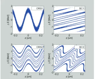
Echo-Enabled Harmonic Generation (EEHG), also known as echo-seeding, is a technique which was proposed in 2008 [1,2] that calls for the co-propagation of an electron bunch and laser pulse through an -undulator, chicane, undulator, chicane- series (Fig. 1). Through interaction with a seed laser, the electron beam develops an energy modulation in the first undulator which is then over- compressed in the first chicane. The electron bunch is then modulated again in the second undulator and compressed in the second chicane, resulting in vertical stripes of charge with a periodicity of a seed laser harmonic (Fig. 2).
EEHG schemes have been proposed for several seeded FELs [3,4,5] and proof-of-principle experiments have been able to generate low-harmonics of the seed laser wavelength [6,7]. These EEHG schemes all call for a large, 1-10 mm, R
56in the first chicane.
E
0=1.15 GeV
Figure 2: ORS-section EEHG scheme. The beam energy is modulated by a laser in the first undulator (ORS1), over-compressed in the first chicane (BC1), modulated again in the second undulator (ORS2), and compressed in the second chicane (BC2). Parameters for this particular 19
thharmonic scheme were, E
0= 1.15GeV, σ
E= 150 keV, λ = 270 nm, ΔE
1= 1.3 MeV, ΔE
1= 0.67 MeV, R
56(1)= 0.55 mm, R
56(2)= 90 μm.
Through a small modification of the first ORS chicane at FLASH, one can achieve a maximum R
56of 0.7 mm and while this is somewhat small compared to other proposed schemes [3,4,5], the amount of laser power available in this section is large, enabling EEHG for seeding wavelengths between 10 and 30 nm. In this paper, the option to use the ORS section to generate bunching at the 19
thharmonic of 270 nm is presented in detail. With a beam energy of 1.15 GeV, there is then the possibility to use the 14 nm sFLASH radiation in an HGHG scheme to produce seeded 4.7 nm in the SASE undulators.
Existing sFLASH diagnostics, like YAG/OTR screens, spectrometers, streak camera, have already been commissioned and are all ideally suited for use as ORS- EEHG diagnostics. The transverse deflecting cavity, LOLA, will be instrumental in diagnosing seed overlap and slice energy spread.
R
56<0.7 mm
λ
rad=4.7 nm λ
rad= 14.1 nm
P<10GW λ
seed=270 nm
ORS und. ORS und.
laser
sFLASH und. SASE und.
Figure 1: The FLASH I ORS section is located directly prior to the sFLASH undulators. The sFLASH undulators are followed by a small chicane and the “SASE” undulators. Using EEHG to seed the sFLASH undulator section with 14 nm could enable an HGHG scheme at 1.15 GeV to seed the SASE undulator section with 4.7 nm. The laser, diagnostics, chicanes, and undulators are already commissioned. A laser transport line and a small modification to the first chicane are all that is needed to complete this scheme.
Proceedings of FEL2011, Shanghai, China TUPB10
FEL Experiments and Projects
ISBN 978-3-95450-117-5
279 Copyright c ○ 2012 by the respecti v e authors/CC BY 3.0 — cc Cr eati v e Commons Attrib ution 3.0 (CC BY 3.0)
To deliver the required laser power to this section in 2012, a new, in-vacuum laser transport line will be constructed during the last 3 months of 2011. A description of the diagnostic, seeding and slicing experiments it will enable is given in [8], the difficulties associated with parasitic operation are explored in [9], simulations and tolerances for this experiment are described in [10], and the hardware and experimental setup are detailed [11]. Here, we will give a condensed version of the material contained in these papers.
THEORY AND SIMULATION
Equation 5 of [1] gives the absolute value of the bunching factor for EEHG harmonic numbers n and m,
2 2
1 ( ))
2( 1 2
1 1 2
2
,m m
( ( ))
n( ( ( ))
nB B mnn
J A B m n J A B n B m n e
b
where A
1,2=ΔE
1,2/σ
Eand B
1,2=2πR
56(1,2)σ
E/(E
0λ) are constants for the first and second undulator and chicane sections. They are written in terms of energy modulation, ΔE, energy spread, σ
E, dispersion, R
56, energy, E
0, and seed wavelength, λ. Typically, when designing an EEHG experiment [3,4,5,6], researchers search for operation parameters using a simplified equation for the bunching factor with a constant n=-1. This gives an accurate prediction of the performance of an EEHG scheme if the R
56is greater than ~1 mm.
When the R
56in the first chicane is small, however, the scheme becomes sensitive to the phase of the laser in the first undulator relative to the phase of the laser in the second undulator. While, strictly speaking, this phase does not change when one uses a single laser, because the phase of the seed laser is written onto the electron beam in the first undulator, changes in this phase are effectively caused by the energy dependent changes in the arrival- time of the electron bunch following the first chicane.
Because the energy stability of the FLASH linac is
~5*10
-4, we should expect phase changes over a full-cycle of the 270 nm seed wavelength and because the sub- millimeter R
56of the chicane produces diagonal charge density streaks instead of completely horizontal streaks, one cannot neglect the influence of the laser phase in low- R
56EEHG theory.
For this low-R
56regime one must remove the absolute value brackets from Eq. 5 of [2] and multiply by e
imφ, where φ is the phase described above. One can then take the sum over all harmonic numbers, m, and phases, φ, in order to predict the phase sensitivity of the bunching factor for harmonic numbers a=m-1.
¦
nm n in
a
e b
b ( M )
M ,(1).
This is similar to Eq. 14 of [2]. In Fig. 3, 1-D particle tracking was done with Matlab and plotted together with the analytic results from Eq. 1 in the n={-10…10} case and the n=-1 case.
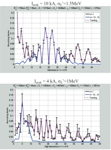
I
peak= 10 kA, σ
E’=1.5MeV
I
peak= 4 kA, σ
E’=1MeV
Figure 3: Bunching factor as a function of harmonic number for two different 14 nm echo-seeding laser power distributions. The error-bars describe the rms sensitivity of each harmonic to changes in the relative arrival-times of the laser pulse and electron bunch in the second undulator. The peak current and energy spread following the EEHG process are written above each plot, together with other important parameters.
While particle tracking takes a cumbersome amount of computing time in a search for an optimal working point, with the analytic solution given by the sum over the phase dependent bunching factors (Eq. 1), one can quickly scan over wide parameter ranges and see features that were not apparent with the n=-1 bunching equation. The bunching factor as a function of harmonic number two different laser powers is plotted in Fig. 3 and the highest peak current for a microbunch is listed above the figure. The bunching factors predicted with the phase dependent bunching formula are plotted together with the n=-1 bunching factor prediction, and results from 1-D particle tracking. Excellent agreement is observed between the phase dependent bunching equation (Eq. 1) and the 1-D particle tracking results. The error-bars describe the rms sensitivity of each harmonic to variations in bunching phase between the two undulators. This sensitivity, together with CSR sensitivity (peak current<10kA) and energy spread (<3*10
-3) are needed to determine an optimal working point.
TUPB10 Proceedings of FEL2011, Shanghai, China
ISBN 978-3-95450-117-5 280
Copyright c ○ 2012 by the respecti v e authors/CC BY 3.0 — cc Cr eati v e Commons Attrib ution 3.0 (CC BY 3.0)
FEL Experiments and Projects
GENESIS SIMULATION
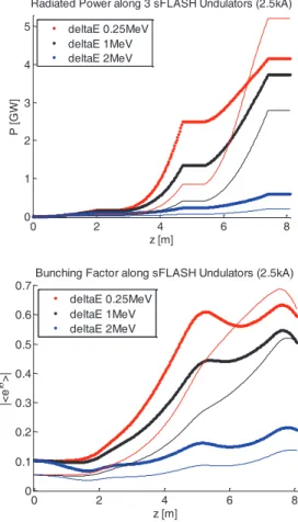
The bunching factors and energy spreads generated with the 1-D tracking code were used in the the FEL code GENESIS to simulate radiation which might be produced in the sFLASH undulators (Fig.4). A 1 MeV energy spread is a reasonable expectation for an EEHG scheme with the ORS section. The sFLASH undulator section is composed of 4 variable gap undulators with a total of 300 periods.
0 2 4 6 8
0 1 2 3 4 5
z [m]
P [GW]
Radiated Power along 3 sFLASH Undulators (2.5kA) deltaE 0.25MeV
deltaE 1MeV deltaE 2MeV
0 2 4 6 8
0 0.1 0.2 0.3 0.4 0.5 0.6 0.7
z [m]
|<eiT>|
Bunching Factor along sFLASH Undulators (2.5kA) deltaE 0.25MeV
deltaE 1MeV deltaE 2MeV
Figure 4: Power and bunching levels in the first three sFLASH undulators for ORS-EEHG seed with a peak current of 2.5 kA and different initial energy spreads and bunching factors. The thick lines are for an 0.1 bunching factor and the thin lines are for an 0.05 bunching factor.
SEED PROPERTIES
The existing sFLASH seed laser system produces 800 nm light with a pulse energy which can be adjusted up to 30 mJ and a pulse length which can be adjusted between 30 fs and a picosecond. The laser in building 28g, together with a pulse compressor is followed by a Galilean telescope. After the telescope, the 16 mm FWHM diameter beam is periscoped down through a hole in the floor into a pit. There is a hole in the wall of the pit which is 7 meters long, ending in the accelerator tunnel. The first of the ORS undulators is 5 meters after the injection point in the tunnel (Fig. 5)
Figure 5: Location of new laser transport line with respect to the accelerator tunnel, laser table and first ORS undulator.
The new, 10
-6mbar evacuated laser transport pipe will start in the pit with a 5 mm thick fused-silica window followed by 8 meters of evacuated DN50 ISO-KF pipe.
The laser beam will then enter the first of two 70x30x30 mm evacuated boxes installed in the accelerator tunnel.
These boxes are followed by another segment of pipe and two flange mounted steering mirrors, the last of which reflects the laser beam onto the electron beam axis. The dimensions of the vacuum pipes, boxes and flange mounted mirrors in the tunnel are depicted below in Fig.
6. The electron beam direction is into the page and the last of the steering mirrors is located in the upper right hand corner directly in front of the cylinder.
Figure 6: Side-view and dimensions of evacuated laser transport line in the accelerator tunnel. Dimensions are given in millimeters. The electron beam direction is into the page in the upper-right corner.
The evacuated boxes will contain optical breadboards on which a frequency tripler, a polarization controller, a Galileo telescope, and two motorized steering mirrors will be mounted. Two more motorized steering mirrors are mounted in vacuum flanges following the boxes. A window directly after the last box marks the transition between the high vacuum (10
-6mbar) of the laser transport line and the ultra-high vacuum (10
-9mbar) of the accelerator. The layout of these components is depicted in Fig. 7.
laser lab 28g
pit
7 meters
e-beam 5 meters
O R S
new laser transport pipe for ORS and EEHG existing laser transport pipe for HHG
e-beam
28g
Proceedings of FEL2011, Shanghai, China TUPB10
FEL Experiments and Projects
ISBN 978-3-95450-117-5
281 Copyright c ○ 2012 by the respecti v e authors/CC BY 3.0 — cc Cr eati v e Commons Attrib ution 3.0 (CC BY 3.0)
Figure 7: Layout of optics in the accelerator tunnel.
Frequency tripler and polarization control optics are followed by a Galileo telescope and four motorized steering mirrors. A window sits between the last two mirrors.
The optics in these boxes will be assembled in a clean room before they are installed in the tunnel. Once they are in the tunnel it will be possible to access the optics by opening one of the panels on the box.
The beam size must be made as large as possible when it travels through windows and air. This is due to the non- linear phase shift in refractive materials. Two Galilean telescopes, one in the laser lab and one in the tunnel, are used to first enlarge the beam and then create a beam waist between the two first undulators. A 760 μm (FWHM) beam waist in the undulator section will be located between the two undulators, so that a 170 fs (FWHM) beam with 1.6 mJ of pulse energy will have a peak intensity of ~1*10
12W/cm
2in each undulator and a non-linear phase shift at the 1 mm thick crystalline quartz window equal to 0.35, a value which is well enough below one that pulse distortions should not be a problem.
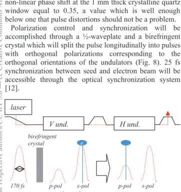
Polarization control and synchronization will be accomplished through a ½-waveplate and a birefringent crystal which will split the pulse longitudinally into pulses with orthogonal polarizations corresponding to the orthogonal orientations of the undulators (Fig. 8). 25 fs synchronization between seed and electron beam will be accessible through the optical synchronization system [12].
Figure 8: Generating a delay between s and p polarization so that the pulse can be used to seed in both undulators.
The undulator labeled H und. produces horizontal oscillations and V und. produces vertical oscillations.
WAVEFRONT CONTROL
An adaptive optics package involving one or two deformable mirrors and measurements of the wavefront will be required in order to modulate the energy of a sufficient portion of the electron bunch with sufficient quality. The quality of the laser wavefronts will directly translate to the quality of the echo-seeding microbunches.
While tilts of the wavefront can be compensated with adjustments of the chicane dispersion, more complicated distortions will directly affect the bunching factor of the goal harmonic.
There are two different locations which could benefit from a deformable mirror: prior to the tripler (out-of- vacuum) and after the tripler (in-vacuum). The out-of- vacuum mirror would be easiest to install and would therefore be the first upgrade attempted. One can tune such a deformable mirror based on measurements using either screen images or direct measurements of the wavefront using a Hartmann sensor. Screens or sensor installed in the electron beam line or before it could all be used in a search for the most effective wavefront control.
Learning algorithms are available for tuning the actuators in a deformable mirror based on either screen images or Hartmann sensor measurements.
CONCLUSION
EEHG is a new technique and the ORS-sFLASH section is suitable for EEHG experiments generating wavelengths ranging from 10 to 30 nm. sFLASH hardware has already been commissioned is ideally suited for use with an ORS- EEHG experiment. The last 3 months of 2011 will provide an opportunity to install an evacuated laser transport line and upgrade the existing first ORS chicane.
Remote control of the laser steering, wavefront, power, and polarization has been designed and purchased. Tests of these systems will begin in November 2011.
ACKNOWLEDGEMENTS
Thank you to Josef Gonschior (DESY) for the drawings and construction work for the chicane and laser transport line. This work was supported by DESY, BMBF, and grant 142-2009-6202 of the Swedish research council.
REFERENCES
[1] D. Xiang and Stupakov,SLAC-PUB-13474, 2008.
[2] G. Stupakov, PRL.102.074801 2009.
[3] E. Allaria, et al., Proc. of FEL’09 (Liverpool).
[4] S. Reiche, et al. Proc. of FEL’09 (Liverpool).
[5] H. Deng, et al., FLASH Beam Dynamics Seminar December 06, 2010.
[6] D. Xiang et al., PRL, 105, 114801 (2010).
[7] Z. T. Zhao et al, Proc. of FEL’10 (Malmoe).
[8] K. Hacker, et al., TESLA-FEL-NOTES-2011-01.
[9] K. Hacker, TESLA-FEL-NOTES-2011-02.
[10] K. Hacker, et al., TESLA-FEL-NOTES-2011-03.
[11] K. Hacker, et al., TESLA-FEL-NOTES-2011-04.
[12] W. Koprek, et al., Proc. of FEL’10 (Malmoe).
5 meters to 1
stundulator
7 meters to building 28g
p-pol
s-pol p-pol s-pol
p-pol
~1 ps 170 fs
birefringent crystal
V und. H und.
laser
e