Context-Aware Process Injection:
Enhancing Process Flexibility by Late Extension of Process Instances
Nicolas Mundbrod, Gregor Grambow, Jens Kolb, and Manfred Reichert Institute of Databases and Information Systems
Ulm University, Germany
{nicolas.mundbrod,gregor.grambow,jens.kolb,manfred.reichert}@uni-ulm.de http://www.uni-ulm.de/dbis
Abstract. Companies must cope with high process variability and a strong demand for process flexibility due to customer expectations, prod- uct variability, and an abundance of regulations. Accordingly, numerous business process variants need to be supported depending on a multiplic- ity of influencing factors, e.g., customer requests, resource availability, compliance rules, or process data. In particular, even running processes should be adjustable to respond to contextual changes, new regulations, or emerging customer requests. This paper introduces the approach of context-aware process injection. It enables the sophisticated modeling of a context-aware injection of process fragments into a base process at design time, as well as the dynamic execution of the specified processes at run time. Therefore, the context-aware injection even considers dy- namic wiring of data flow. To demonstrate the feasibility and benefits of the approach, a case study was conducted based on a proof-of-concept prototype developed with the help of an existing adaptive process man- agement technology. Overall, context-aware process injection facilitates the specification of varying processes and provides high process flexibility at run time as well.
Keywords: Process Injection, Process Flexibility, Process Variability, Process Adaptation, Data Collection Processes
1 Introduction
In today’s globalized world, companies face various challenges like increased customer expectations, complex products and services, demanding regulations in different countries, or fulfillment of social responsibility. As a result, com- panies need to cope with high process variability as well as a strong demand for process flexibility. This means that in many of their business processes the course of action is influenced by an abundance ofprocess parameterslike external context factors, intermediate results, and process-related events (e.g., successful termination of process steps). Consequently, ordinary process models comprise complex decisions allowing for various alternative courses of actions as well as
interdependencies among these decisions that are hardly comprehensible for pro- cess modelers. In addition, an automated, controlled and sound adaptation of (long-running) processes instances is required to address contextual changes, new regulations, or emerging customer requests at run-time.
The complex development, production, or reporting processes in the auto- motive and electronics industry may be regarded as valuable examples [12,18,8].
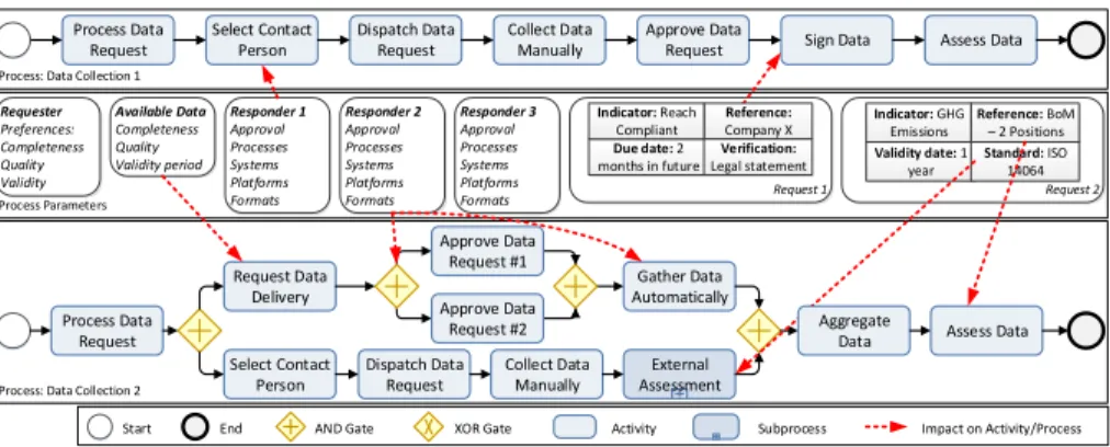
Typically, these processes rely on the companies’ sensitive supply chains. Hence, business partners and diverse activities have to be incorporated dynamically on demand. The following application scenario (cf. Fig. 1), we derived in the context of a case study, illustrates the complexity and dynamics of such processes.
Application Scenario:Data Collection Processes
Due to regulations, an automotive manufacturer needs to provide sustain- ability information. In particular, sustainability indicators relating to its production are requested: one indicator deals with the REACHacompliance of the entire company, another one addresses the greenhouse gas emissions during the production of a certain product. To gather the data, processData Collection 1 is deployed to request a REACH compliance statement from a supplier. Additionally, two other suppliers must be contacted to report the greenhouse gas emissions (processData Collection 2). While both data collection processes have activities in common, many activities are specif- ically selected for each process. A request regarding REACH compliance, e.g., implies a legally binding statement and, thus, a designated represen- tative must sign the data. However, if the CEO was not available, activity Sign Data can be delayed or skipped.
a Regulation (EC) No 1907/2006: Registration, Evaluation, Authorisation and Restriction of Chemicals
Dispatch Data Request
External Assessment Requester
Preferences:
Completeness Quality Validity
Responder 1 Approval Processes Systems Platforms Formats Available Data Completeness Quality Validity period
Collect Data
Manually Sign Data Assess Data
Gather Data Automatically
Assess Data Process Data
Request
Approve Data Request #2 Approve Data
Request #1 Select Contact
Person
Request Data Delivery
Dispatch Data Request Select Contact
Person
Approve Data Request
Responder 2 Approval Processes Systems Platforms Formats
Responder 3 Approval Processes Systems Platforms Formats Process Parameters
Process: Data Collection 1
Process: Data Collection 2
Start End AND Gate XOR Gate Activity Subprocess Impact on Activity/Process
Request 1 Request 2
Validity date: 1 year
Reference: BoM – 2 Positions Standard: ISO
14064 Indicator: GHG
Emissions
Process Data Request
Collect Data Manually
Aggregate Data Due date: 2
months in future Reference:
Company X Verification:
Legal statement Indicator: Reach
Compliant
Fig. 1: Application Scenario with two Data Collection Processes
To systematically support long-running and varying processes that require (data-driven) run-time flexibility, we introduce the approach of context-aware process injection (CaPI). Taking the current context of a process into account,
CaPI enables the controlled, but late injection (i.e., insertion) of process frag- ments into a lean base process. Using so-calledextension areas, the correctness of the process’ control and data flow is ensured after injecting process fragments at run time. The feasibility of CaPI is demonstrated by implementing a proof-of- concept prototype based on existing adaptive process management technology.
Underpinning our research, we applied thedesign scienceresearch methodol- ogy [15]. In particular, our work can be categorized as adesign- and development- centered approachaccordingly. Based on an analysis of application scenarios (e.g., [11,17,8]) and process-related backgrounds (cf. Sect. 2) as well as the evaluation of existing approaches (cf. Sect. 7), we iteratively elaborated the CaPI approach (cf. Sect. 3). The latter comprises the specification of its components (cf. Sect.
4). Furthermore, we give insights into the process of context-aware process in- jection (cf. Sect. 5). To validate the approach, a poof-of-concept prototype was developed enabling the usage and evaluation in different application scenarios (cf. Sect. 6). Finally, Section 8 concludes the paper giving a summary and an outlook.
2 Backgrounds
To make CaPI applicable to existing activity-centric process modeling notations, it relies on the process model definition given in Def. 1.
Definition 1. A process model P M is a tuple(N, E, N T, ET, EC)where:
– N is a set of process nodes andE⊆N×N is a precedence relation (directed edges) connecting process nodes,
– N T :N → {Start,End,Activity,ANDsplit,ANDjoin,ORsplit,ORjoin, XORsplit,XORjoin,DataObj} assign to each n∈N a node type N T(n);
Nis divided into disjoint sets of start/end nodesC(N T(n)∈ {Start,End}), activitiesA (N T(n) =Activity), gatewaysG (N T(n)∈ {ANDsplit, ANDjoin,ORsplit,ORjoin,XORsplit,XORjoin}), and data objects D (N T(n) =DataObj),
– ET : E → {ControlEdge,LoopEdge,DataEdge} assigns a type ET(e) to each edgee∈E,
– EC : E → Conds∪ {T rue} assigns a transition condition or true to each control edgee∈E, ET(e)∈ {ControlEdge,LoopEdge}.
Note that we take sound process models for granted, i.e., a process model has one start (no incoming edges) and one end node (no outgoing edges) [17]. Further, the process model has to be connected, i.e., each activity can be reached from the start node, and from each activity the end node is reachable. Data consumed (delivered) as input (output) by the process model is written (read) by the start (end) node. Finally, branches may be arbitrarily nested, but must be safe (e.g., a branch following anXORsplitmust not merge with anANDjoin). Due to lack of space, we refer to literature for a detailed look on process model soundness [19].
Def. 2 introduces the notion of aSESE (Single Entry Single Exit) fragment:
Definition 2. Let P M := (N, E, N T, ET, EC) be a process model and N0 ⊆ N be a subset of activities. The subordinated process model P M0 induced by N0 and their corresponding edgesE0 ⊆E is denoted asSingle Entry Single Exit (SESE) fragment iff P M0 is connected and has exactly one incoming and one outgoing edge connecting it with PM. IfP M0 has no preceding (succeeding) nodes, P M0 has only one outgoing (incoming) edge.
Based on a process modelP M, a process instanceP I may be created, de- ployed and executed at run time. Def. 3 defines a process instance formally:
Definition 3. Aprocess instanceP Iis defined as a tuple(P M, N S, Π)where:
– P M := (N, E, N T, ET, EC)denotes the process modelP I is executed on, – N S:N→ {NotActivated,Activated,Running,Skipped,Completed}
describes the execution state of each noden∈N with N T(n)6=DataObj, – Π:=he1, . . . , enidenotes the current execution trace ofP I where each entry
ek is related either to the start or completion of an activity.
3 Context-Aware Process Injection in a Nutshell
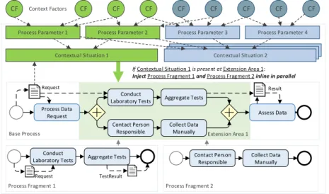
The key objective of CaPI is to ease the sophisticated modeling of process vari- ants at design time and to enable the automated, controlled adaption of processes at run time. Therefore, the central entity of CaPI is the context-aware process family (CPF) (cf. Fig. 2). In detail, a CPF comprises a base process model with extension areas (cf. Sect. 4.1), contextual situations (cf. Sect. 4.3) based onprocess parameters (cf. Sect. 4.2), a set ofprocess fragments injected at the extension areas at run time, and a set ofinjection specifications (cf. Sect. 4.4).
Base Process
CF CF CF CF CF CF CF CF CF
Process Parameter 1 Process Parameter 2 Process Parameter 3 Process Parameter 4
Extension Area 1 Conduct
Laboratory Tests Aggregate Tests
Contact Person Responsible
Process Fragment 1 Process Fragment 2
Conduct Laboratory Tests
If Contextual Situation 1 is present at Extension Area 1:
Inject Process Fragment 1 and Process Fragment 2 inline in parallel Contextual Situation 1 Contextual Situation 2Process Situation 3Process Situation 3 Context Factors
Request
Aggregate Tests
Collect Data Manually
Request TestResult
Result
Contact Person Responsible
Collect Data Manually
Assess Data Process Data
Request
Fig. 2: Overview of a Context-Aware Process Family
Establishing theseparation of concerns principle for modeling process vari- ants, thebase process modelsolely contains decisions and activities shared by all variants of the process, known at build time, and not being changed at run time.
By contrast,extension areas represent the dynamic part of the process. Hence, a process modeler may focus on modeling predictable activities first to add the dynamic parts of the base process model subsequently. In particular, extension areas are used to automatically inject process fragments into the base process at run time based on the presentcontextual situation as well as on well-definedin- jection specifications. An extension area allows for the dynamic injection of any number of parallel process fragments. In turn, contextual situations are defined through conditions expressed in first-order logic takingprocess parameters and even data objects of the base process model into account. In this context, process parameters are connected to dynamic, external factors influencing the process in- jection’s decision making. While injecting process fragments, CaPI takes care of correct data flow mappings as well: data objects of an injected process fragment are automatically connected to existing ones of the base process.
By this means, CaPI enables controlled, but dynamic configurations and changes of long-running and varying processes at run time. Through relying on insertions of process fragments solely, CaPI allows process modelers to increas- ingly focus on the particular variants instead of struggling with a highly complex process model capturing all variants.1 Furthermore, process modelers may di- rectly integrate contextual influences into the modeling of variants as complex external context factors are abstracted by meaningful process parameters and reusable contextual situations. In turn, CaPI is able to cope with contextual run-time changes through the late evaluation of contextual situations at given extension areas to finally inject the proper process fragments. Thereby, the au- tomated and consistent construction of data flow between the injected process fragments and the underlying base process mitigates the efforts of involved users.
Further, it empowers process activities to seamlessly read and write data.
Before presenting the key components of a CPF and CaPI, Def. 4 formally specifies the concept of acontext-aware process family (CPF). Note that a pro- cess fragment may be the base process of another CPF and, thus, modularization can be achieved as well (recursive nesting is disallowed).
Definition 4. Acontext-aware process familyis defined as a tupleCP F = (BP, EA, P P, CS, P F, IS) where:
– BP is the base process model,
– EAis a set of extension areas in theBP, – P P is a set of process parameters, – CS is a set of contextual situations,
– P F is a set of process fragments; each process fragment is a process model, – IS is a set of injection specifications.
1 Note that other kind of dynamic changes, like deleting or moving activities, may be also introduced by authorized users based on the features of the adaptive process management technology [6] used.
4 Components of Context-Aware Process Families
4.1 Extension Areas
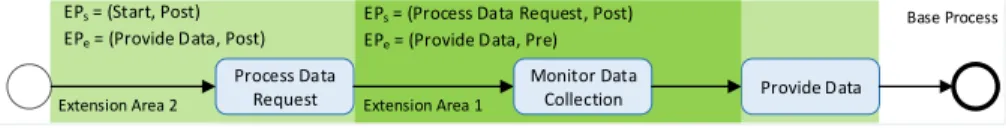
In order to enable the controlled extension of processes at run time, extension areas are introduced representing the dynamic part of a CPF. Based on the current contextual situation, process fragments may be dynamically injected into extension areas at run time. More precisely, an extension area is defined by two extension points—each referring to a node (i.e. start/end nodes, activities, gateways) of the base process model (cf. Fig. 3). If the nodes referenced by the extension points directly precede each other, a process fragment can be easily injected into the base process. If some nodes exist in between, a process fragment may be injected among these nodes (cf. Sect. 4.4) or, alternatively, gateways may be employed to insert the process fragment in parallel. The different possibilities of injecting process fragments are discussed in Section 5. Def. 5 formally describes extension areas and posits constraints to ensure that the injection of process fragments into a base process BP always leads to a modified, but still sound processBP0. In this context, overlaps of extension areas may result in problems regarding the concurrent injection of process fragments (cf. Sect. 5.2).
Definition 5. Let CP F = (BP, EA, P P, CS, P F, IS) be a context-aware pro- cess family and BP = (N, E, N T, ET, EC) be the base process. Every exten- sion areaea∈EA is described by a set of two extension points{EPs, EPe} ⊆ N× {Pre,Post} where:
– Every extension pointEPx= (nx, scope), x∈ {s, e} refers to corresponding nodesnx∈N, N T(nx)6=DataObj inBP and additionally exposes a scope;
the latter determines whetherea starts (ends) just before (scope=Pre) or directly after (scope=Post) the referenced nodenx,
– EPs (EPe) may only refer to the scope Post (Pre) of the start (end) node ofBP;EPs (EPe) must not refer to the end (start) node ofBP,
– The referenced nodesns, ne∈N embrace a subordinated process modelP M0 induced by a subset of activities N0 ⊆ N and respective edges E0 ⊆ E;
P M0 always corresponds a SESE fragment and must not contain any other extension areas starting (ending), but not ending (starting) inP M0 (nesting of extension areas is allowed, but no overlaps).
Base Process
Extension Area 2
Process Data
Request Provide Data
Extension Area 1
EPs = (Process Data Request, Post) EPe = (Provide Data, Pre) EPs = (Start, Post)
EPe = (Provide Data, Post)
Monitor Data Collection
Fig. 3: Examples of Extension Areas in a Base Process
4.2 Process Parameters
Typically, long-running and varying processes are influenced by context factors, e.g., the number of involved parties or the availability of data. To include such context factors into the decision making regarding the injection of process frag- ments and hence the concrete course of action of the overall process, we utilize a predefined set ofprocess parameters (cf. Def. 6). The set of process parameters additionally enables the exchange of entire CPFs between application scenarios as it abstracts from a concrete set of context factors (i.e., only a mapping between the context factors and process parameters need to be conducted again).
Definition 6. Let CP F = (BP, EA, P P, CS, P F, IS) be a context-aware pro- cess family. Aprocess parameterpp∈P P is a tuple (ppDef ault, ppV alue, ppDom)where:
– ppDef ault∈P P Dom is an optional default value of the process parameter, – ppV alue∈P P Dom is the current value of the process parameter,
– ppDom⊆Domis the domain ofppwithDomdenoting the set of all atomic domains (e.g., String, Integer)
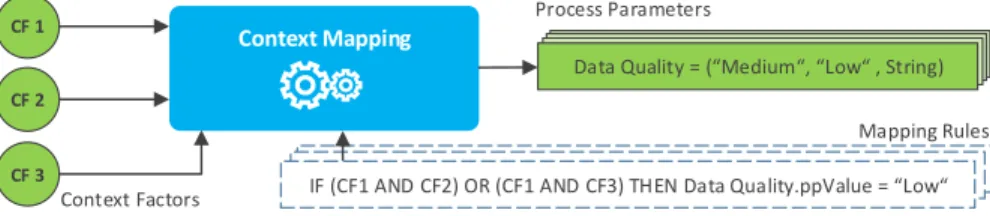
Note that valueppV alue of process parameter pp is set by a context map- ping (component) at run time (cf. Sect. 5.2). To focus on the controlled process adaption, we rely on simple rule-based mapping for context factors (cf. Fig. 4).
CF 1
CF 2
CF 3
Context Mapping
Data Quality = ( Medium , Low , String)
Context Factors
Process Parameters
Mapping Rules IF (CF1 AND CF2) OR (CF1 AND CF3) THEN DataQuality = Low IF (CF1 AND CF2) OR (CF1 AND CF3) THEN DataQuality = Low IF (CF1 AND CF2) OR (CF1 AND CF3) THEN Data Quality.ppValue = Low
Fig. 4: Illustrative Mapping of Context Factors on Process Parameters Consequently, process parameters may be also leveraged to provide meta information regarding the current execution trace (cf. Def. 3) or the process fragments injected at run time. Such process parameters can then be used to model interdependencies among contextual situations and process fragments, respectively. Finally, a process parameter may have compound values (e.g., sets, lists) as well—however, we omit a formal definition of complex parameters here.
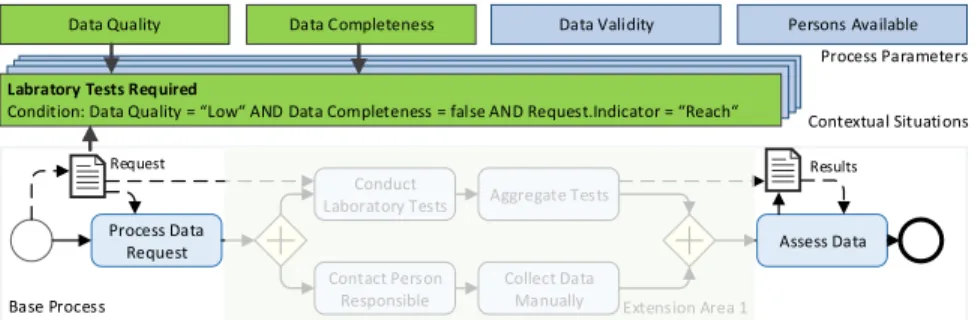
4.3 Contextual Situations
A specific process variant may rely on several occurring contextual situations, which are based on the combination of various process parameters and, espe- cially, their current values. For example, a company may insist on a four-eyes- principle approval process in case data is intended for a specific customer group or relates to a specific regulation. Hence, the same contextual situations may be leveraged at different extension areas to inject process fragments. Based on this
observation, contextual situations (cf. Fig. 5) are defined by conditions expressed in a first-order logic relying on the set of process parameters (cf. Sect. 4.2) and data objects of the base process (cf. Def. 7). As opposed to traditional modeling of business processes, we enable the integration of external context factors as well as reutilization of contextual situations across the process model. As de- fault process parameters may provide meta information regarding the current execution trace or the process fragments injected at run time, interdependencies can be modeled in contextual situations correspondingly.
Data Quality Data Completeness
Labratory Tests Required
Condition: Data Quality = Low AND Data Completeness = false AND Request.Indicator = Reach
Data Validity Persons Available
Process Parameters
Contextual Situations Request
Base Process
Process Data
Request Assess Data
Extension Area 1 Conduct
Laboratory Tests Aggregate Tests
Contact Person Responsible Request
Collect Data Manually
Results
Fig. 5: Contextual Situation based on Process Parameters and Data Objects
Definition 7. Let CP F = (BP, EA, P P, CS, P F, IS) be a context-aware pro- cess family andBP = (N, E, N T, ET, EC)be the corresponding base process. A contextual situationcs∈CS is defined by a condition expressed in first-order logic. For every predicate park θ valk, θ∈ {“=“,“ ≤“, . . .}, valk ∈Dom(park) of the condition,park either corresponds to a process parameter (park ∈P P) or a data object (park ∈N, N T(park) =DataObj).
4.4 Injection Specifications
Finally,injection specifications determine the injection of a process fragment to an extension area in a given contextual situation (cf. Def. 5). To ensure data flow correctness after the injection, in addition, the mapping of data elements is considered in the injection specifications. Especially, this includes a mapping of required input and output data objects of the process fragment (or, to be more precise, of their activities) to the existing data objects of the base process.
This mapping may be even extended to data objects of other process fragments, which are supposed to be injected in the base process as well (cf. Sect. 5).
Definition 8. Let CP F = (BP, EA, P P, CS, P F, IS) be a context-aware pro- cess family and BP = (N, E, N T, ET, EC) be the corresponding base process.
Aninjection specificationis∈IScorresponds to a tuple(EAIS, CSIS, P FIS, InjT ype, InjP attern, InjRate, InjT rigger, InjRank, DR, DW) where:
– EAIS ∈ EA is a specific extension area, CSIS ∈CS a specific contextual situation, andP FIS ∈P F a specific process fragment,
– InjT ype:={Inline,Sub-process} is the injection type denoting whether P FIS is injected inline or as a sub-process,
– InjP attern := {Parallel,Sequential} is the injection pattern denoting whetherP FIS is injected in parallel to the existing control flow between the extension points ofEAIS or sequentially into the existing control flow, – InjRate:={Single,(Multiple,fre)} is the injection rate denoting whether
P FIS is injected once or multiple times atEAIS; the latter requires attribute fre∈Ndetermining how oftenP FIS shall be injected atEAIS in parallel, – InjT rigger determines the point in time an injection is triggered. It is
defined by a conditional predicate par θ val with par ∈ NS
P P; further par∈N ⇒N T(par) =DataObj, θ∈ {“=“,“≤“, . . .}, val∈Dom(par), – InjRank∈Nis a number to create a ranking among injections specifications
as they may match concurrently; all injection specifications for one particular extension area must expose different values,
– DR : InputDataP FIS → DO is a set of mappings of input data objects InputDataP FIS ofP FIS to data objectsDO∈NBPS(NP F\NP FIS)of the base processBP or of other process fragments P F \P FIS,
– DW :OutputDataP FIS →DO is a set of mappings of output data objects OutputDataP FIS of P FIR to data objects DO ∈NBPS
(NP F \NP FIS) of the base processBP or of other process fragments P F \P FIS.
The injection trigger (InjT riger) enables the injection of a process fragment at an extension area as soon as a given process parameter or data object exposes a certain value (see Sect. 5.2 for details). Furthermore, the number of process fragments to be injected may be dynamically set based on the current contex- tual situation. Both concepts increase the flexibility provided to long-running and varying processes. The ranking (InjRank) of injection specifications be- comes necessary as several contextual situations may occur concurrently and, hence, several injections (cf. Sect. 4.4) may be concurrently triggered. Through the ranking, especially, sequential injections of process fragments can be accom- plished in a well-defined order. Sect. 5 presents details on context-aware process injection based on injection specifications.
5 The Process of Context-aware Process Injection
This section discusses theprocess of context-aware process injection to reveal the interplay and benefits of the introduced components and concepts. In particular, we show how to employ CaPI entities to properly inject process fragments at extension areas in given contextual situations. Thereby, we both discuss alter- natives to specify CPFs at design time as well as the process of context-aware process injection at run time.
5.1 The Modeling of Context-aware Process Families
As a prerequisite, the base process of a context-aware process family must be defined first. Therefore, either a new process model needs to be created or an
existing one is modified accordingly. Note that the resulting base process model solely contains the set of activities shared by all process variants, known at build time, and usually not being changed at run time. Drawing upon, the extension areas are then defined by selecting corresponding nodes in the base process.
Subsequently, the set of process parameters must be specified as the latter provides the basis for defining contextual situations and, finally, the injection specifications. In this context, a process modeler may demand a set of pre-defined process parameters that allow modeling interdependencies among process frag- ments. For example, the list of process fragments injected in the base process at run time may be made available through such a pre-defined process param- eter. Note that this approach also allows for the incorporation of data objects, which belong to other process fragments, into the data mapping declared in an injection specification.
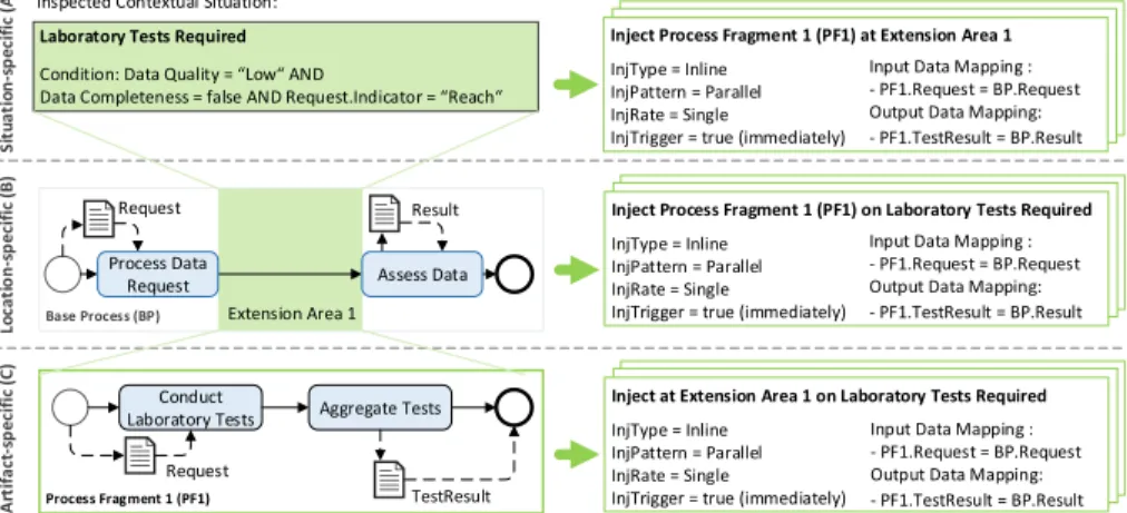
Based on the given process parameters and data objects, the set of contex- tual situations can be defined appropriately. The latter then enables a process modeler to finally define injection specifications. Altogether, three alternative modeling perspectives can be provided to a process modeler (cf. Fig. 6):
– Situation-based perspective: for every contextual situation, one may deter- mine the process fragments to be injected at given extension areas.
– Location-based perspective: for each extension area, one may define the pro- cess fragments to be injected in a given contextual situation.
– Artifact-based perspective:one may stepwise take process fragments to define in which contextual situation they shall be injected at given extension areas.
Situation-specific (A)Location-specific (B)Artifact-specific (C)
Inspected Contextual Situation:
Laboratory Tests Required Condition: Data Quality = Low AND
Data Completeness = false AND Request.Indicator = Reach
Base Process (BP) Extension Area 1
Request Result
Process Fragment 1 (PF1) Conduct
Laboratory Tests Aggregate Tests
Request
TestResult
Inject Process Fragment 1 (PF1) at Extension Area 1 in Base Process (BP) InjType = Inline
InjPattern = Parallel InjRate = Single InjTime = true (immediately)
Input Data Mapping : - PF1.Request = BP.Request Output Data Mapping:
- PF1.TestResult = BP.Result Inject Process Fragment 1 (PF1) at Extension Area 1 in Base Process (BP) InjType = Inline
InjPattern = Parallel InjRate = Single InjTime = true (immediately)
Input Data Mapping : - PF1.Request = BP.Request Output Data Mapping:
- PF1.TestResult = BP.Result Inject Process Fragment 1 (PF1) at Extension Area 1 InjType = Inline
InjPattern = Parallel InjRate = Single
InjTrigger = true (immediately)
Input Data Mapping : - PF1.Request = BP.Request Output Data Mapping:
- PF1.TestResult = BP.Result
Inject Process Fragment 1 (PF1) at Extension Area 1 in Base Process (BP) InjType = Inline
InjPattern = Parallel InjRate = Single InjTime = true (immediately)
Input Data Mapping : - PF1.Request = BP.Request Output Data Mapping:
- PF1.TestResult = BP.Result Inject Process Fragment 1 (PF1) at Extension Area 1 in Base Process (BP) InjType = Inline
InjPattern = Parallel InjRate = Single InjTime = true (immediately)
Input Data Mapping : - PF1.Request = BP.Request Output Data Mapping:
- PF1.TestResult = BP.Result Inject Process Fragment 1 (PF1) on Laboratory Tests Required InjType = Inline
InjPattern = Parallel InjRate = Single
InjTrigger = true (immediately)
Input Data Mapping : - PF1.Request = BP.Request Output Data Mapping:
- PF1.TestResult = BP.Result
Inject Process Fragment 1 (PF1) at Extension Area 1 in Base Process (BP) InjType = Inline
InjPattern = Parallel InjRate = Single InjTime = true (immediately)
Input Data Mapping : - PF1.Request = BP.Request Output Data Mapping:
- PF1.TestResult = BP.Result Inject Process Fragment 1 (PF1) at Extension Area 1 in Base Process (BP) InjType = Inline
InjPattern = Parallel InjRate = Single InjTime = true (immediately)
Input Data Mapping : - PF1.Request = BP.Request Output Data Mapping:
- PF1.TestResult = BP.Result Inject at Extension Area 1 on Laboratory Tests Required InjType = Inline
InjPattern = Parallel InjRate = Single
InjTrigger = true (immediately)
Input Data Mapping : - PF1.Request = BP.Request Output Data Mapping:
- PF1.TestResult = BP.Result Process Data
Request Assess Data
Fig. 6: Three Approaches for Modeling Injection Specification
As illustrated in Fig. 6, from each perspective the modeling still leads to the creation of injection specifications for the given CPF. However, a process modeler may use her favorite approach or even mix the approaches in relation to her personal preferences.
Since many activities and decisions in the control flow of the base process may be data-driven, the mapping of the injected data objects must be accomplished to successfully conduct CaPI. This very essential part for supporting process variants is consistently and easily achieved by selecting the data objects in both the base process model and the process fragments to create the required mapping (cf. Sect. 4.4). Note that this is a clear advantage of CaPI in comparison to many existing approaches (cf. Sec. 7) as the latter do not allow for (automatic) data mapping and, hence, process users are burdened with this issue at run time. As process fragments may be injected at different extension areas, one may want to link a data object to another data object of a process fragment injected earlier in the base process. Hence, a interdependency between such two process fragments must be created accordingly: process parameters providing meta information regarding the current execution trace (cf. Sect. 4.2) are leveraged to enhance the contextual situation for a process fragment. The latter can be easily automated as soon as one adds corresponding references to data objects of process fragments to be injected earlier. Finally, in case a process fragments is injected multiple times at an extension area, CaPI allows for referencing data objects of the injected fragments by adequate identification mechanisms.
5.2 The Execution of Context-aware Process Families
As opposed to configuration approaches (cf. Sec. 7), CaPI enables the late con- figuration of processes at run time. The latter allows evaluating the contextual situations just in the moment a process adaptation is required. Therefore, a CP F = (BP, EA, P P, CS, P F, IS) is deployed and executed in a process-aware information system (PaIS). After successful deployment, the base process in- stance BP I = (BP, N S, Π) is continuously monitored by a dedicated CaPI application (cf. Sect. 6.1) continuously monitoring the BPI regarding reached extension areas and current contextual situations.
If an extension area ea ∈ EA is reached and, especially, its first exten- sion point refers to a node with scope Pre (EPs = (nx,Pre), nx ∈ N, BP = (N, E, N T, ET, EC)), the determination of the contextual situations will be started as soon as the previous node will have been completed (nx−1 ∈ N, N S(nx−1) = Completed). In turn, if the first extension point refers to a node with scopePost(EPs= (nx,Post)), the determination will be started as soon as nxwill have been completed (N S(nx) =Completed). In case the extension area is surrounded by a loop in theBP I, the injection specification can be evaluated in the first iteration or in every iteration of the loop structure (depends on pref- erences and the support by th underlying PaIS). After successfully determining the set of contextual situations CSea, it becomes possible to derive the set of utilizable injection specificationsISea for finally adapt the BPI adequately.
For every process specificationis∈ISea withis= (ea, csis, pfis, InjT ypeis, InjP atternis, InjRateis, InjT riggeris, InjRankis, DRis, DWis), the point of time the process injection shall be accomplished, must be regarded based on condition InjT riggeris. If the latter is already met when reachingea,pfiswill be immedi- ately injected according to the below-mentioned steps. Otherwise, the injection
ofpfiswill be postponed untilInjT riggeris is fulfilled. In case the condition is never satisfied,pfiscould be injected at the very end of the control embraced by an extension area or not be injected at all (depends on preferences set initially). If pfisshall be lately injected, the current states of the nodes embraced byeamust be taken into account: if there is only one running node nx∈N(i.e.N S(nx) = Running), pfis will be injected directly afternx. However, if there are several concurrently running nodesnk ∈N, k = 1, . . . , n(i.e.N S(nk) =Running),pfis
will be injected directly after the gateway finally merging the branches on which the nodesn1, . . . , nnare situated on. Finally, if several injection specifications are sharing the same contextual situations and injection trigger, the injection rank InjRankisis considered (cf. Sect. 4.4). After the consideration ofInjT riggeris
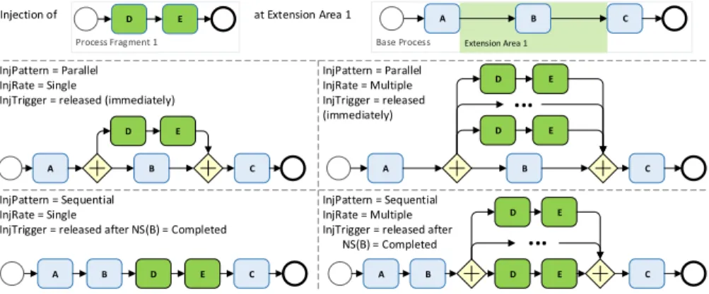
andInjRankis, the following procedures are applied in general (cf. Fig. 7):
1. InjP atternis = Parallel∧InjRateis =Single, ⇒ pfis will be injected inline (or as a sub-process depending onInjT ypeis) and in parallel to the existing control flow,
2. InjP atternis = Parallel∧InjRateis = (Multiple,fre), ⇒ pfis will be injected inline (or as a sub-process) fre times with surroundingANDsplit/ ANDjoingateways in parallel to existing control flow,
3. InjP atternis=Sequential∧InjRateis=Single⇒,pfis will be injected inline (or as a sub-process) into the existing control flow,
4. InjP atternis=Sequential∧InjRateis= (Multiple,fre),⇒pfis will be injected inline (or as a sub-process) fre times with surroundingANDsplit/ ANDjoingateways into the existing control flow.
InjPattern = Parallel InjRate = Single
InjTrigger = released (immediately)
InjPattern = Sequential InjRate = Single
InjTrigger = released after NS(B) = Completed
InjPattern = Sequential InjRate = Multiple InjTrigger = released after NS(B) = Completed InjPattern = Parallel InjRate = Multiple InjTrigger = released (immediately)
A B C
B D B C
D E
A E
A B C
D E
D E
...
D E
D E
...
C
Injection of at Extension Area 1
Base Process Extension Area 1
A B C
Process Fragment 1
D E
A
Fig. 7: Realization of Process Injection based on Injection Specifications The detailed procedures to inject a process fragment pfis are exemplar- ily discussed for the case InjP atternis = Parallel∧InjT ypeis = Inline, assuming InjT riggeris has already been satisfied: first, start and end nodes nspf
si, nepf
is ∈Npfis ofpfis are removed. Then all remaining nodesnkpf
is∈Npfis as well as one ANDsplit nAN Dsplit and one ANDjoin gateway nAN Djoin are added to the nodes of the base process NBP. Subsequently, six control edges are created: one edge connectsnp preceding the extension area withnAN Dsplit,
two edges link nAN Dsplit to ns+1pf
is, which succeeds the (removed) start node of pfis, andnp+1, which is the first node in the control flow embraced byea. Sub- sequently, ne−1pf
is (i.e, the last node of pfis) and ea (i.e, last node of the control flow embraced byea) are connected with nAN Djoin. Finally,nAN Djoinis linked tons, which is the first node succeedingea.
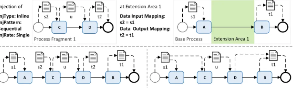
Finally, the correct data flow between injected nodes and existing nodes of the base process must be established. As this is automatically performed at run time, process participants are not burdened with this challenging task. We exemplarily present the data input mapping for the inline injection of a single fragment P FIS (cf. Fig. 8): for every node npfis of pfis with data edge edi = (dipfis, nP FIS)∈E, ET(e) =DataEdgefrom a input data objectdipfis, dipfis ∈ InputDatapfis, a new edgeedi-new:= (doBP, npfis) is created based on mapping dr= (dipfis, doBP), dr∈DR.ediis deleted afterwards and if there are no further edges connectingdipfis to nodes, dipfis will be deleted as well.
Injection of InjType: Inline InjPattern:
Sequential InjRate: Single
at Extension Area 1 Data Input Mapping:
s2 = s1
Data Output Mapping:
t2 = t1
Base Process Extension Area 1
A B
Process Fragment 1
C D
s2 u t2 s1 t1
A B
s1 t1
C D
s2 u t2
A B
s1 t1
C D
u
Step 1: Removing the start + end nodes; injection into control flow Step 2: Establishing data flow by using input and output mapping
Fig. 8: Data Mapping Example for an Injected Process Fragment
6 Validation
As the CaPI approach explicitly addresses long-running processes showing high variability, which often take place in rather sensitive businesses, a mature and powerful implementation is required to conduct valuable empirical studies to successfully validate the concepts presented in this work. To prepare such stud- ies, we developed a sophisticated proof-of-concept prototype whose details are presented in the following. Further, we conducted a first case study in the au- tomotive and electronics industry to receive important feedback regarding both the approach in total as well as the proof-of-concept prototype in particular.
6.1 Proof-of-Concept Prototype
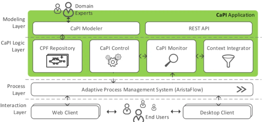
To establish a powerful implementation as a solid basis for future empirical stud- ies, the CaPI proof-of-concept prototype is based on the conceptual architecture shown in Fig. 9. In particular, we realized the prototype using Aristaflow adap- tive process management technology [6]. The latter allows modeling, deploying, and executing well-structured business processes. Further, it provides sophisti- cated and sound change operations to adapt running process instances at run
time [16]. Hence, AristaFlow provides the basic execution platform required to conduct the sound injection of process fragments as well as the proper assign- ment of data objects for the injected activities at run time.
CaPI Application
CaPI Modeler REST API
CaPI Control
Adaptive Process Management System (AristaFlow)
End Users Domain
Experts
CPF Repository +
Context Integrator CaPI Monitor
BPMS Desktop ClientDesktop Client BPMS Web ClientWeb Client
Modeling Layer CaPI Logic Layer
Process Layer Interaction Layer
Fig. 9: Overview on the CaPI Architecture
Realized with Java Enterprise Edition 7, the CaPI application comprises a web-based sub-module enabling domain experts to conveniently model CPFs (CaPI Modeler) as well as sub-modulesCPF Repository, CaPI Monitor, CaPI Control, and Context Integrator representing the CaPI core functions required at run time.
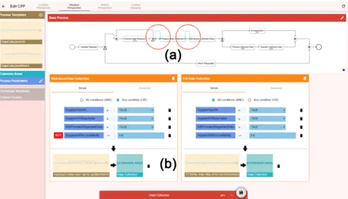
Through appropriate web-based user interfaces, a domain expert may first specify the mappings of the available context factors to process parameters and the one of the process parameters to contextual situations accordingly. Based on these preparations, she may create injection specifications by putting together the CaPI core components extension areas, contextual situations and process fragments via drag and drop. As proposed in Sect. 5.1, for this purpose, we implemented the different perspectives a domain expert may use to create an in- jection specification. Consequently, Fig. 10 exemplarily illustrates the situation- based perspectives showing a base process with two extension areas (see Marking (a)) for a data collection process regarding Reach Compliance of several suppli- ers (cf. Sect. 1). Both extension areas are needed to prepare and perform data collection activities for every involved supplier according to their capabilities (i.e. context factors). In particular, if a supplier hosts a well-reachable in-house system providing required data, the process fragment“Perform Data Collection IHS” is injected for every involved supplier at the second extension area.
Overall, the CPFs modeled by domain experts are managed in the CPF Repository. At run time, CaPI Control interprets the CPF specifications to de- tect the deployment of a CPF base process in AristaFlow and to continuously monitor the execution of the base process accordingly. Therefore, CaPI Control is registered as a dedicated service in AristaFlow to receive any status updates of activities as well as to actively acknowledge the start of every activity in the
base process. Based on this approach, CaPI control detects when achieving an extension area, subsequently evaluates the valid contextual situations, and fi- nally injects the specified process fragments on demand. For the example of Fig.
10, either “Perform Data Collection IHS” or “Web-based Data Collection” are injected at the second extension area according to the given contextual situations at run time (see Marking (b)).
Fig. 10: Screenshots of the CaPI Situation-based Modeling Perspective
6.2 Case Study
After demonstrating the technical feasibility, we also conducted a case study based on data collection processes in the automotive and electronics industry (cf. Sect. 1) in the scope of the SustainHub2project. More precisely, we therefore modeled several data collection processes of an automotive manufacturer with its dynamic, data-driven injections of process fragments. Ensuing, we conducted qualitative interviews with project partners to receive their feedback. For the interviews, we presented both the approach and the existing functionality based on the modeled data collection process. Altogether, we received valuable, but of course limited feedback regardingbetter modularity,increased confidentiality, andcomprehensible monitoring.
Regarding modularity, CaPI may reduce the complexity of long-running, varying process models to create more comprehensible and appropriate process models according to given contextual situations. The partners stated that the size and complexity of process models typically determine the rate of model- ing errors. CaPI may provide a different way of modeling such complex and
2 SustainHub (Project No.283130) is a collaborative project within the 7th Framework Programme of the European Commission (Topic ENV.2011.3.1.9-1, Eco-innovation).
varying processes without these errors. However, the possibilities and ease-of- use regarding the modeling of contextual situations and injection specifications will mainly determine the effectiveness and efficiency of CaPI in comparison to the traditional approach of maintaining one large-sized process model. At design time, the systematic management of large process models also raises the problem of confidentiality. All possible decisions and activities including the linkage to roles, data, and other resources are accessible in total. According to the part- ners, modeling a process based on CaPI may provide possibilities to separate common activities and control flow from specific, confidential process fragments injected in contextual situations. Regarding confidentiality at run time, CaPI may provide only activities and control flow elements executed for monitoring purposes. Thereby, monitoring may be more comprehensible and descriptive in comparison to showing execution traces in large and complex process models.
7 Related Work
Classifying CaPI, we propose an implemented approach for the automated, context-aware extension of process instances at run time to cope with process variability and to increase process flexibility. Related work addresses the config- uration of process models before deployment, the adaptation of process instances at run time, the late selection of sub-process, the late composition of services [17,3], and, in broader sense, aspect-oriented programming. In the following we discuss the commonalities and differences of related work in comparison to CaPI.
Approaches for process configuration, e.g., [9] or [7], aim at the modification of a reference process model to configure process model variants before pro- cess run time. Therefore, these approaches employ various transformations like adding process fragments, deleting activities, or changing control flow as well as properties of activities. However, these powerful transformations can be only applied, based on current information, before the process has been deployed. In- stead, CaPI enables the injection of process fragments at run time. Further, CaPI considers context- and process-specific data at run time to support both process variability and process flexibility for long-running processes. Regarding auto- mated adaptation of process instances at run time, rule-, case, and goal-based approaches may be taken into account [17]. Based on ECA (Event-Condition- Action), the rule-based approaches automatically detect exceptional situations and determine process instance adaptations required to handle these exceptions.
Especially, AgentWork [13] is based on a temporal ECA rule model and enables automated structural adaptations of a running process instance (e.g., to add process fragments or to delete them) to cope with unplanned situations.
However, CaPI entities allow for the specification of process variants instead of coping with unexpected failure events. Concretizing loosely specified processes, approaches forlate selection typically rely on placeholder activities to integrate sub-processes in a base process at run time. While [1] suggests that the selec- tion of the process fragment is primarily done by the process participants, [14]
proposes an automatic, multi-staged approach to select sub-process at run time.
Further, CaPI may be compared to process-based composition methods allowing for the late selection of service implementations [5,2,4]. These approaches share the abstract definition of a business process at design time. Each activity in the business process corresponds to a service specification and provides a place- holder for services matching the specification. Either upon invocation time or at run time, service implementations matching the specification are automatically selected from a registry based on QoS attributes or selection rules. By contrast, CaPI’s extension areas in combination with injection specifications enable both the inline insertion of process fragments as well as the integration of process fragments as sub-processes. While placeholder activities are limited regarding the assignment of input and output data, the declaration of data mappings in the injection specifications enables the direct access to of activities in the process fragments to data objects in the base process.
Regarding related work in a broader sense, CaPI can be also well compared to aspect-oriented programming (AOP) [10]. AOP represents a programming paradigm for object-oriented programming and it targets high modularity by allowing and realizing the separation of system-level cross-cutting concerns from the actual key functionality. While AOP is also relying on injections at so-called join points, CaPI, by contrast, targets at the increased modularity of varying processes by separating activities, which are always performed, from activities and sub-processes performed in certain, pre-defined contextual situations.
8 Conclusion
In a nutshell, this work presents an approach for supporting long-running pro- cesses being subject to high variability by the context-aware and automated in- jection of process fragments at run time. Especially for long-running processes, the important configuration addressing process variety can hardly be performed solely at build time. However, existing approaches either focus on build-time configurations or allow for the late selection of process fragments based on place- holder activities. Consequently, the CaPI approach addresses this gap through providing context-aware configuration support at run-time based on the injection of process fragments. Finally, we further addressed the important data mapping for injected process fragments as well as we implemented a proof-of-concept prototype demonstrating the mentioned CaPI benefits.
In future research, we will conduct comprehensive experiments using the prototype to further examine the process of context-aware process injection.
We further intend to enhance the CaPI modeler and to strengthen the context mapping by employing complex event processing.
Acknowledgement
This research was partially conducted within the SustainHub research project (Project No.283130) funded by 7th Framework Programme of the European Commission (Topic ENV.2011.3.1.9-1, Eco-innovation).
References
1. Adams, M., ter Hofstede, A. H. M., Edmond, D., van der Aalst, W. M. P.: Worklets:
A service-oriented implementation of dynamic flexibility in workflows. In: Proc.
OTM’06. pp. 291–308 (2006)
2. Aggarwal, R., Verma, K., Miller, J., Milnor, W.: Constraint driven web service composition in METEOR-S. In: Proc. SCC 2004. pp. 23–30 (2004)
3. Ayora, C., Torres, V., Weber, B., Reichert, M., Pelechano, V.: VIVACE: A framework for the systematic evaluation of variability support in process-aware information systems. Information and Software Technology 57, 248–276 (2015) 4. Canfora, G., Di Penta, M., Esposito, R., Villani, M.L.: A framework for QoS-aware
binding and re-binding of composite web services. J Systems and Software 81(10), 1754–1769 (2008)
5. Casati, F., Shan, M.C.: Dynamic and adaptive composition of e-services.
Information systems 26(3), 143–163 (2001)
6. Dadam, P., Reichert, M.: The ADEPT Project: A Decade of Research and Development for Robust and Flexible Process Support - Challenges and Achievements. Computer Science - Research and Development 23(2), 81–97 (2009) 7. Gottschalk, F., van der Aalst, W. M. P, Jansen-Vullers, M.H., La Rosa, M.:
Configurable workflow models. Int J Coop Inf Sys 17(02), 177–221 (2008) 8. Grambow, G., Mundbrod, N., Steller, V., Reichert, M.: Challenges of Applying
Adaptive Processes to Enable Variability in Sustainability Data Collection. In:
SIMPDA’13. pp. 74–88. CEUR Workshop Proceedings (2013)
9. Hallerbach, A., Bauer, T., Reichert, M.: Context-based Configuration of Process Variants. In: Proc. TCoB 2008. pp. 31–40 (2008)
10. Kiczales, G., Lamping, J., Mendhekar, A., Maeda, C., Lopes, C., Loingtier, J.M., Irwin, J.: Aspect-Oriented Programming. In: Proc. ECOOP’97. pp. 220–242 (1997) 11. Lanz, A., Kreher, U., Reichert, M., Dadam, P.: Enabling Process Support for Advanced Applications with the AristaFlow BPM Suite. In: Proc. Business Process Management 2010 Demo Track. CEUR Workshop Proceedings (2010)
12. M¨uller, D., Reichert, M., Herbst, J.: A new paradigm for the enactment and dynamic adaptation of data-driven process structures. In: Proc. CAiSE’08. pp.
48–63 (2008)
13. M¨uller, R., Greiner, U., Rahm, E.: AgentWork: a workflow system supporting rule- based workflow adaptation. Data & Knowledge Engineering 51(2), 223–256 (2004) 14. Murguzur, A., Carlos, X.d., Trujillo, S., Sagardui, G.: Context-Aware Staged Configuration of Process Variants@Runtime. In: Proc. CAiSE’14. pp. 241–255 (2014)
15. Peffers, K., Tuunanen, T., Rothenberger, M.A., Chatterjee, S.: A Design Science Research Methodology for Information Systems Research. J Management Information Systems 24(3), 45–77 (2007)
16. Reichert, M., Dadam, P.: ADEPTflex - Supporting Dynamic Changes of Workflows Without Losing Control. J Intelligent Information Systems 10(2), 93–129 (1998) 17. Reichert, M., Weber, B.: Enabling Flexibility in Process-Aware Information
Systems: Challenges, methods, technologies. Springer, Heidelberg (2012)
18. Tiedeken, J., Reichert, M., Herbst, J.: On the Integration of Electrical/Electronic Product Data in the Automotive Domain. Datenbank Spektrum 13(3), 189–199 (2013)
19. van der Aalst, W. M. P., ter Hofstede, A. H. M.: Verification of Workflow Task Structures: A Petri-net-based Approach. Inf Sys 25(1), 43–69 (2000)