A Real-Time Scene Understanding System for Airport Apron Monitoring
David Thirde, Mark Borg and James Ferryman Computational Vision Group
The University of Reading Whiteknights, Reading, RG6 6AY, UK { D.J.Thirde, M.Borg, J.Ferryman } @reading.ac.uk
Florent Fusier, Val´ery Valentin, Franc¸ois Br´emond and Monique Thonnat ORION Team
INRIA Sophia-Antipolis, 2004 Route des Lucioles BP 93 06902 Sophia-Antipolis, France
{Florent.Fusier, Valery.Valentin, Francois.Bremond, Monique.Thonnat}@sophia.inria.fr
Abstract
This paper presents a distributed multi-camera visual surveillance system for automatic scene interpretation of airport aprons. The system comprises two main modules
— Scene Tracking and Scene Understanding. The Scene Tracking module is responsible for detecting, tracking and classifying the objects on the apron. The Scene Understand- ing module performs high level interpretation of the apron activities by applying cognitive spatio-temporal reasoning.
The performance of the complete system is demonstrated for a range of representative test scenarios.
1. Introduction
This paper describes work undertaken on the EU project.
The main aim of this project is to automate the supervision of commercial aircraft servicing operations on the ground at airports (in bounded areas known as aprons, shown in Figure 1). A combination of visual surveillance and video event recognition algorithms are applied in a multi-camera end-to-end system providing real-time recognition of the activities and interactions of numerous vehicles and person- nel in a dynamic environment.
In visual surveillance the tracking of objects is com- monly achieved using top-down(e.g. [11]) or bottom-up methods. Bottom-up tracking generally refers to a process comprising two sub-processesmotion detectionandobject tracking; bottom-up tracking is generally computationally efficient compared to the top-down method.
Tracking algorithms have to deal with motion detec- tion errors and complex object interactions. Apron analy- sis presents further challenges due to the size of the vehi- cles tracked (e.g. the aircraft size is34×38×12metres), therefore prolonged occlusions occur frequently throughout congested apron operations. Many of the objects are also of near-identical appearance, consequently appearance-based matching performs poorly in such a scenario.
Figure 1. The distribution of equipment around a parked aircraft in apron E40 at Toulouse Airport.
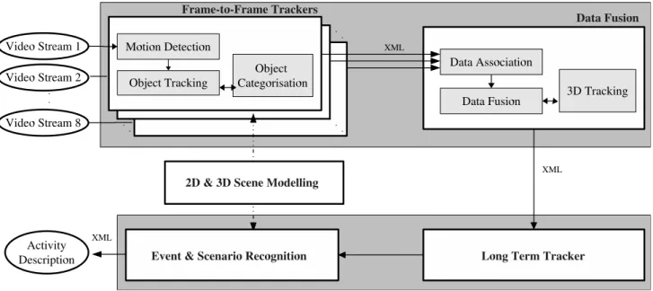
Figure 2. The system architecture deployed for the AVITRACK project.
Video event recognition algorithms analyse tracking re- sults spatially and temporally to automatically recognise the high-level activities occurring in the scene; for aircraft ser- vicing analysis such activities occur simultaneously over extended time periods in apron areas. Recent work by Xi- anget al[15] applied a hierarchical dynamic Bayesian net- work to recognise scene events; however, such models are incapable of recognising simultaneous complex scene activ- ities in real-time over extended time periods. The approach adopted for AVITRACK [13] addresses these problems us- ing cognitive vision techniques based on spatio-temporal reasoning, a priori knowledge of the observed scene and a set of predefined video events corresponding to aircraft service operations.
Section 2 gives an overview of the deployed system. Sec- tion 3 details the Scene Tracking module comprising per- camera motion detection, bottom-up feature-based object tracking and finally fused object tracking using the com- bined object tracking results from the camera agents. Sec- tion 4 describes the Scene Understanding module includ- ing both the representation of video events and the video event recognition algorithm itself applied to apron monitor- ing. Section 5 presents the results, while Section 6 contains the discussion and lists future work.
2. System Overview
The system deployed is a decentralised multi-camera en- vironment with overlapping fields of view (FOV); currently, eight cameras are used to monitor the scene. This system is suitable for monitoring airport aprons since there are sev-
eral mounting points for cameras on the airport building and overlapping fields of view are required to ensure consistent object labelling and enhanced occlusion reasoning within the scene. The majority of the camera mounting points ob- serve the right hand side of the fuselage since this is where most of the servicing operations (such as baggage loading and unloading) take place; on the left hand side of the fuse- lage, the servicing operation of interest is the refuelling op- eration. Spatial registration of the cameras is performed us- ing per camera coplanar calibration and the camera streams are synchronised temporally across the network by the cen- tral video server.
The architecture of the system is shown in Figure 2 comprising two main modules -Scene TrackingandScene Understanding. In the Scene Tracking module a Frame Trackermodule runs independently for each of the cameras, performing motion detection, frame to frame object track- ing and object categorisation. A centralData Fusionmod- ule receives the single-camera observations from the Frame Tracker modules, fuses the observations and generates 3D results to maximise the useful information content of the scene being observed. In the Scene Understanding module a Long-Term Tracker uses a temporal window to provide trajectory information required for event recognition and behaviour analysis. The Event and Scenario Recognition module uses the tracking results to perform event detection and high level scene interpretation. An offlineScene Mod- elling module is used to generate geometric and semantic scene and object models, as well as defining video event models.
The system must be capable of monitoring and recognis-
ing the activities and interaction of numerous vehicles and personnel in a dynamic environment over extended periods of time, operating in real-time (12.5 FPS,720×576resolu- tion) on colour video streams. The relatively low quantity of the distributed modules and the physical distances between them allows the network to be operated via a standard 1Gb ethernet.
The communications framework selected for the dis- tributed modules is via a OROCOS::SmartSoft CORBA [9]
implementation. The modules communicate using the XML standard; although inefficient for communication over a net- work, the XML standard allows the system to be efficiently integrated as a series of black box modules with a defined interface between them. The partners in the project are able to develop the modules independently while adhering to the XML interface standard; this standardisation allowed the modules to be successfully integrated in the end-to-end sys- tem with few problems. The added advantage of the XML is that the human operators can manually inspect the XML to explain some system failures that may occur during inte- gration.
3. Scene Tracking
The Scene Tracking module is responsible for the per- camera detection and tracking of moving objects, trans- forming the image positions into 3D world co-ordinates, and fusing the multiple camera observations of each object into single world measurements.
3.1. Frame-to-Frame Tracking
For detecting connected regions of foreground pixels,16 motion detection algorithms were implemented for AVIT- RACK and evaluated quantitatively on various apron se- quences under different environmental conditions (sunny conditions, fog, etc.). The metrics adopted, the evaluation process and the results obtained are described in more de- tail in [1]. Taking into account processing efficiency as well as sensitivity, the colour mean and variance method was se- lected [14]. This motion detector has a background model represented by a pixel-wise Gaussian distributionN(µ, σ2) over the normalised RGB colour space. In addition, a shadow/highlight detection component based on the work of Horprasertet al[8], is used to handle illumination vari- ability. The algorithm also employs a multiple background layer technique to allow the temporary inclusion into the background model of objects that become stationary for a short period of time.
For real-time object tracking, the KLT algorithm [10] is used, and it considers features to be independent entities and tracks each of them individually. Therefore, it is incor- porated into a higher-level tracking process that groups the
sparse local features into objects, maintain associations be- tween features and objects, and uses the individual tracking results of the features to track the objects globally, while taking into account complex object interactions. To man- tain the association between features and objects from one frame to the next, the spatial information and the motion in- formation of features are used. Spatial rule-based reasoning is applied to detect the presence of merging or splitting fore- ground regions, based on the idea that if a feature belongs to an object at timet−1, then the feature should remain spatially within the foreground region of the object at time t. The motion of the individual features are robustly fitted to translational and affine motion models to estimate the mem- bership of features to objects. If the motion models are not distinct or unreliable then spatial-based reasoning is used;
otherwise a combination of both is used.
On the apron, activity tends to happen in congested ar- eas with several vehicles being stationary in the proximity of the aircraft. To allow stationary and moving objects to be differentiated, the motion detection process was extended to include a multiple background layer technique. The tracker identifies stopped objects by one of two methods: analysing an object’s region for connected foreground pixels which have been labelled as ‘motion’ over a time window; or by checking the individual motion of local features of an ob- ject. The accuracy of the second method depends on the feature density parameter ρ. Stationary objects are inte- grated into the motion detector’s background model as dif- ferent background layers. The advantage this method has over pixel level analysis (such as that used by Collins et al[6]) is that for extended time periods (e.g. 30 minutes) pixel level methods tend to result in fragmented layers that do not represent cohesive objects. More detail about the Scene Tracking module can be found in [12].
To efficiently recognise the people and vehicles on the apron, a multi-stage categorisation approach is adopted: the first stage consists of a bottom-up process that categorises the main object categories (people, ground vehicles, aircraft or equipment); this is achieved using a Gaussian mixture model classifier trained on efficient descriptors such as 3D width and height, dispersedness and aspect ratio. This is inspired by the work of Collinset al[6] where it was shown to work well for distinct object classes.
The second classification stage is applied to the vehi- cle category to recognise the individual vehicle sub-types (e.g. loader vehicle, tanker, etc.), which cannot be deter- mined from simple descriptors. Hence, a proven top-down method [7, 11] is applied to fit textured 3D models to the detected objects in the scene. These models are fitted to the image data by back projection and evaluated using nor- malised cross-correlation to determine the best model pose.
The performance of this 3D model fitting is excellent for many of the vehicle categories with few false matches. A
Figure 3. (Left) Tracking results for 3 cameras for frame 9126 of sequence 21. (Middle) shows data fusion results on the ground-plane for the sequence (9600 frames) with the vehicle track shown in white. (Top-right) the fused observation (in black) for the vehicle (frame 9126) using the covariance accumulation method, (Middle-right) shows the result for covariance intersection. (Bottom-right) shows the sensory uncertainty field measured for camera 6.
problem of this method is the computational complexity;
this problem is solved by running the algorithm on a back- ground (threaded) process to the main (bottom-up) track- ing system and updating the object classification when it is available. For AVITRACK, the vehicle sub-type only be- comes important for event recognition when a vehicle stops near the aircraft; the time delay from when a vehicle first enters the camera view until it stops near the aircraft is nor- mally enough to allow the second stage classification to be completed.
3.2. Data Fusion
The Data Fusion module is based on a nearest neighbour Kalman filter approach [3] with a constant velocity model.
The measurement uncertainty is estimated by propagating a nominal image uncertainty using the method presented in [4]. The measurement uncertainty field is shown in Fig- ure 3 for camera 6; this estimate of uncertainty allows for- mal methods to be used to associate observations originat- ing from the same measurement, as well as providing mech- anisms for fusing observations into a single estimate.
In the association step a validation gate [3] is applied to
limit the potential matches between tracks and observations.
Matched observations are fused to find the estimate of the location and uncertainty of the object, based on covariance intersection. Covariance intersection estimates the fused uncertainty for a set of matched observations as a weighted inverse summation; the weighting is chosen such that it is in favour of the sensors that have more certain measurements.
The fused observations are demonstrated in Figure 3; the (unweighted) covariance accumulation method [4] results in a more localised estimate of the fused measurement than the covariance intersection approach. More detail about the Data Fusion module can be found in [12].
4. Scene Understanding
The Scene Understanding module is responsible for the recognition of video events in the scene observed through video sequences. This module performs a high-level inter- pretation of the scene by detecting video events occurring in it. The method to detect video events uses cognitive vi- sion techniques based on spatio-temporal reasoning,a pri- oriknowledge of the observed environment and a set of pre- defined event models which are written using the descrip-
Figure 4. (Left) The model of the composite state “Vehicle Stopped Inside Zone”: a vehicle is de- tected as stopped inside a zone of interest. (Right) The model of the primitive event “Enters Zone”:
a vehicle enters a zone of interest.
tion language described in [5]. A Video Event Recognition module takes the tracked mobile objects from the previously described modules as input, and outputs video events that have been recognised. The a prioriknowledge exploited includes the camera information, the vehicle models, the expected moving objects and the empty scene model con- taining the contextual objects.
Currently a set of 21 basic video events have been de- fined, including 10 primitive states, 5 composite states and 6 primitive events. These basic video events are used in the definition of video events representing the handling oper- ations. The primitive states correspond to spatio-temporal properties related to persons and vehicles involved in the scene. Some examples include: a person is located inside a zone of interest, a person is close to a vehicle, a vehicle is lo- cated inside a zone of interest, a vehicle is close to another vehicle, a vehicle has stopped, etc. Using these primitive states, different composite states have been modelled, such as: a person stays inside a zone of interest, a vehicle has arrived in a zone of interest, and a vehicle has stopped in a zone of interest (shown in Figure 4). The composite states have in turn been used to model different primitive events, for example: a person enters a zone of interest, a person moves between zones of interest, a vehicle enters a zone of interest (shown in Figure 4), a vehicle moves between zones of interest, etc. These states and events are then used in the definition of the composite events (modelling behaviours) representing the apron operations.
4.1. Video Event Representation
The video event representation corresponds to the spec- ification of all the knowledge used by the system to detect video events occurring in the scene. To allow experts in the aircraft activity monitoring to easily define and modify the video event models, the description of the knowledge is declarative and intuitive (in natural terms). The video event representation is based on the video event description lan- guage described in [5]. Thus, the video event recognition uses the knowledge represented by experts through event models. The proposed model of a video event E is com- posed of five parts:
• a set of Physical Object variables corresponding to the physical objects involved in E: any contextual object including static object (equipment, zone of interest) and mobile object (person, vehicle, aircraft, etc.) The vehicle mobile objects can be of different subtypes to represent different vehicles (GPU, Loader, Tanker, etc.)
• a set of temporal variables corresponding to the com- ponents (sub-events) of E.
• a set of forbidden variables corresponding to the com- ponents that are not allowed to occur during the detec- tion of E.
• a set of constraints (symbolic, logical, spatial and tem- poral constraints including Allen’s interval algebra op- erators [2]) involving these variables.
• a set of decisions corresponding to the tasks predefined by experts that need to be executed when E is detected (e.g. activating an alarm or displaying a message).
There are four types of video events: primitive state, composite state, primitive event and composite event. A state describes a situation characterising one or several physical objects defined at timetor a stable situation de- fined over a time interval. A primitive state (e.g. a per- son is inside a zone) corresponds to a vision property di- rectly computed by the vision module. A composite state, as shown in Figure 4, corresponds to a combination of prim- itive states. An event is an activity containing at least a change of state values between two consecutive times (e.g.
a vehicle leaves a zone of interest - it is inside the zone and then it is outside). A primitive event, as shown in Figure 4, is a change of primitive state values and a composite event is a combination of states and/or events.
4.2. Video Event Recognition
The video event recognition algorithm recognises which events are occurring in a stream of mobile objects tracked by the vision module. The recognition of composite states
Figure 5. (Left) Two dynamic zones (in blue) linked with the Loader and the Transporter vehicles involved in the detected event “Worker Manipulating Container” (event 26). (Right) The Unloading operation involves 8 physical objects and 3 composite components with 2 constraints on the vehicle subtypes, 4 constraints on the zones of interest and 2 temporal constraints.
and events usually requires a search in a large space com- posed of all the possible combinations of components and objects. To avoid this combinatorial explosion, all compos- ite states and events are simplified into states and events composed of at most 2 components through a stage of com- pilation in a preprocessing phase. Then the recognition of composite states and events is performed in a similar way to the recognition of primitive events, as described in the method of Vuet al[13].
In the Video Event Recognition module,a prioriknowl- edge corresponds to apron zones of interest (access zones, stopping zones), aircraft and vehicle (e.g. GPU, Loader, Tanker and Transporter) models. In apron monitoring, some problems may occur while trying to build an accurate con- text of the scene. For example, access zones to aircraft can be at different positions according to the aircraft type. To solve these problems, dynamic properties have been added to thea prioriknowledge, by defining dynamic zones in the local coordinate system of vehicles. Figure 5 illustrates the use of dynamic context. This notion of dynamic context al- lows more complex scenarios to be defined in which mobile objects can directly interact with each other.
4.3. Predefined Video Events
Current work is on video events involving (1) the GPU (Ground Power Unit) vehicle which operates in the aircraft arrival preparation operation, (2) the Tanker vehicle which operates in the refuelling operation and (3) the Loader and Transporter vehicles which are involved in the baggages
loading/unloading operations. To recognise these opera- tions 28 composite video events were defined, including 8 video events for the aircraft arrival preparation operation, 8 video events for the refuelling operation, and 12 video events for the unloading operation.
The aircraft arrival preparation operation (event 8) in- volves the GPU, its driver and 4 zones of interest. The system recognises that the GPU vehicle arrives in the ERA Zone (event 1), obeys the speed limit (event 2); then it en- ters (event 3) and stops (event 4) in the “GPU Access Area”, the driver gets out of the vehicle (event 5) and deposits the chocks and stud at the location where the plane will stop (events 6 and 7). This operation and another modelled one, the refuelling operation, are considered to be basic opera- tions because they only consist of one person and one vehi- cle.
The baggage unloading operation (Figure 5) is more complex. This operation involves both a Loader and a Transporter vehicle, the conductor of the Loader, and a per- son working in the area. This operation is composed of the following steps: first, the Loader vehicle arrives in the ERA zone (event 17), enters its restricted area (event 18) and then stops in this zone (event 19); a dynamic zone is automatically added, at the rear of the Loader’s stop po- sition (“Loader Arrival”, event 20), where the Transporter will enter and stop. When the Transporter enters (event 21) and stops (event 22) in this zone (“Transporter Arrival”, event 23), another dynamic zone is automatically added to the context. The back of the Loader is then elevated (event
24) and the baggage containers are unloaded from the air- craft by the Loader conductor (event 25) one by one. The conductor unloads these containers into the dynamic zone of the Transporter where a worker arrives (event 26) and directs the containers (event 27) on to the Transporter.
5. Results
The Scene Tracking evaluation assesses the performance of the three core components (motion detection, object tracking and data fusion) on representative test data.
The performance evaluation of the different motion de- tector algorithms for AVITRACK is described in more de- tail in [1]. It is noted that some objects are partially de- tected due to the achromaticity of the scene and the pres- ence of fog causes a relatively high number of foreground pixels to be misclassified as highlighted background pix- els resulting in a decrease in accuracy. Strong shadows also cause problems, often detected as part of the mobile objects.
The performance evaluation of the tracking algorithm is de- scribed in more detail in [12]. In is noted that some objects can produce a ghost which remains behind the previous ob- ject position. An object is integrated into the background when it becomes stationary for an extended time period.
In these cases, ghosts are created when stationary objects start to move again. Partial detection of objects can result in fragmentation in tracked objects with similar colour as the background.
The Data Fusion module performs adequately given cor- rectly detected objects in the Frame Tracker (a representa- tive result is shown in Figure 3). The Data Fusion mod- ule incorporates uncertainty information in the location es- timate of the observation and it is often an inaccurate loca- tion estimate that results in the failure of the data association step; a significant proportion of the localisation problems that occur in the Data Fusion module can be traced back to motion detection errors i.e. shadow, reflections etc.
The Scene Understanding evaluation have been per- formed on sequences for which the tracking module gives good results. Video event recognition has been tested on sequences involving the GPU (aircraft arrival prepa- ration operation), the Tanker (refuelling operation) and the Loader/Transporter vehicles (baggage unloading oper- ation).
Video events 1 to 4 involving a GPU have been tested on a dataset of 4 scenes corresponding to 2×4video se- quences (containing from 1899 to 3774 frames and includ- ing one night sequence). These events are detected with a perfect True Positive rate. The video events 4 to 8 involving also a GPU have been tested on 2 scenes corresponding to 2 video sequences because only one camera is available to observe these events. The video events involving the Tanker have been tested on one scene (more than 15000 frames cor-
Vehicle type Sequence TP FP FN GPU
Events 1 to 4 4 scenes * 2 cam. 32 0 0
Events 4 to 8 2 scenes * 1 cam. 8 0 0
Tanker
Events 9 to 13 2 scenes * 1 cam. 10 0 0 Events 14 to 16 1 scene * 1 cam. 3 0 0 Loader-Transporter
Events 17 to 28 1 scenes * 1 cam. 12 0 0
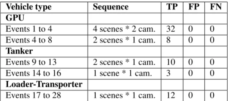
Table 1. Performance results of the Scene Un- derstanding module for apron monitoring. TP
= “Event exists in the real world and is well recognised”, FN = “Event exists in the real world but is not recognised”, FP = “Event does not exist in the real world but is recog- nised”.
responding to about 30 minutes) showing the “Tanker Ar- rival” (event 13) and the driver of the Tanker branching the refuelling pipe to the aircraft (events 14, 15, 16). The “Un- loading Baggage operation” involving the Loader (events 17 to 20, event 24 and event 25) and the Transporter (events 21 to 23) have been tested on one scene where the cameras point of view allows to fully observe the vehicle movements and interactions between vehicles and people.
The results of the qualitative evaluation are shown in Ta- ble 1. The goal is to give an idea of the performance of the Scene Understanding and to anticipate potential problems in event detection for apron monitoring. All video events are recognised correctly (49 TPs) without false alarms (0 FPs) and misdetection (0 FNs). These results are very en- couraging but one has to keep in mind that situations where the vision module misdetects or overdetects mobile objects were not addressed.
6. Discussion and Future Work
The results are encouraging for the presented system.
The performance of the Scene Tracking module provides adequate results; however, tracking is sensitive to signifi- cant dynamic and static occlusions within the scene. Future work will address shadow/ghost supression and explicit oc- clusion analysis.
The Scene Understanding results show that the proposed approach is adapted to apron monitoring and can be applied to complex activity recognition. The recognition of com- plex operations in parallel (e.g. “baggage unloading”) in- volving people and vehicles gives encouraging results. Fu- ture work will incorporate uncertainty to enable recognition
of events even when the Scene Tracking module gives un- reliable output.
Acknowledgement
This work was supported by the European Union, grant AVITRACK (AST3-CT-3002-502818)1.
References
[1] J. Aguilera, H. Wildernauer, M. Kampel, M. Borg, D. Thirde, and J. Ferryman. Evaluation of motion segmenta- tion quality for aircraft activity surveillances. InProc. Joint IEEE Int. Workshop on VS-PETS, Beijing, Oct 2005.
[2] J. F. Allen. Maintaining knowledge about temporal intervals.
InCommunications of the ACM, volume 26 num 11, pages 823–843, Nov 1983.
[3] Y. Bar-Shalom and X. Li.Multitarget-Multisensor Tracking:
Principles and Techniques. YBS Publishing, 1995.
[4] J. Black and T. Ellis. Multi Camera Image Measurement and Correspondence. InMeasurement - Journal of the In- ternational Measurement Confederation, volume 35 num 1, pages 61–71, 2002.
[5] F. Br´emond, N. Maillot, M. Thonnat, and V. Vu. Ontologies for video events. InResearch report number 51895, Nov 2003.
[6] R. Collins, A. Lipton, T. Kanade, H. Fujiyoshi, D. Duggins, Y. Tsin, D. Tolliver, N. Enomoto, O. Hasegawa, P. Burt, and L. Wixson. A system for video surveillance and monitoring.
InTech. Report CMU-RI-TR-00-12, May 2002.
[7] J. M. Ferryman, A. D. Worrall, and S. J. Maybank. Learning enhanced 3d models for vehicle tracking. In Proc. of the British Machine Vision Conference, 1998.
[8] T. Horprasert, D. Harwood, and L. Davis. A statistical approach for real-time robust background subtraction and shadow detection. InIEEE ICCV’99 FRAME-RATE Work- shop, 1999.
[9] C. Schlegel. A component approach for robotics software:
Communication patterns in the orocos context. In18. Fach- tagung Autonome Mobile Systeme (AMS), Informatik ak- tuell, pages 253–263. Springer, Karlsruhe, Dec 2003.
[10] J. Shi and C. Tomasi. Good features to track. InProc. of IEEE Conference on Computer Vision and Pattern Recogni- tion, pages 593–600, 1994.
[11] G. D. Sullivan. Visual interpretation of known objects in constrained scenes. InPhil. Trans. R. Soc. Lon., volume B, 337, pages 361–370, 1992.
[12] D. Thirde, M. Borg, V. Valentin, F. Fusier, J.Aguilera, J. Fer- ryman, F. Br´emond, M. Thonnat, and M.Kampel. Visual surveillance for aircraft activity monitoring. InProc. Joint IEEE Int. Workshop on VS-PETS, Beijing, Oct 2005.
[13] V. Vu, F. Br´emond, and M. Thonnat. Automatic video inter- pretation: A novel algorithm for temporal event recognition.
InIJCAI’03, Acapulco, Mexico, Aug 2003.
1However, this paper does not necessarily represent the opinion of the European Community, and the European Community is not responsible for any use which may be made of its contents.
[14] C. R. Wren, A. Azarbayejani, T. Darrell, and A. Pentland.
Pfinder: Real-time tracking of the human body. InIEEE Transactions on PAMI, volume 19 num 7, pages 780–785, 1997.
[15] T. Xiang and S. Gong. On the structure of dynamic bayesian networks for complex scene modelling. In Proc. Joint IEEE Int. Workshop on Visual Surveillance and Performance Evaluation of Tracking and Surveillance (VS-PETS), pages 17–22, Oct 2003.