Prototyping of a multicell superconducting cavity for acceleration of medium-velocity beams
C. C. Compton, T. L. Grimm, W. Hartung, H. Podlech,* and R. C. York
National Superconducting Cyclotron Laboratory, Michigan State University, East Lansing, Michigan 48824, USA G. Ciovati and P. Kneisel
Thomas Jefferson National Accelerator Facility, Newport News, Virginia 23606, USA D. Barni, C. Pagani, and P. Pierini
INFN Milano —Laboratorio LASA, 20090 Segrate (Milano), Italy (Received 24 June 2004; published 11 April 2005)
Three 6-cell 805 MHz superconducting cavity prototypes for acceleration in the velocity range of about 0.4 to 0.53 times the speed of light have been fabricated and tested. The quality factors (Q0) were between 7109 and 1:41010 at the design field (accelerating gradient of 8–10 MV=m). The maximum gradients reached were between 11 and16 MV=m; in each case, the Q0values were3109 at the maximum gradient. The design, fabrication, surface preparation, and rf testing of the 6-cell cavities are reported in this paper.
DOI: 10.1103/PhysRevSTAB.8.042003 PACS numbers: 84.40. –x, 85.25.Am, 52.70.Gw, 29.17.+w
I. INTRODUCTION
Superconducting accelerators are presently used to ac- celerate particles that are light enough to havev=c 1(electrons and positrons) or heavy enough (ions) to have 1(wherevis the beam velocity andcis the speed of light). Historically, superconducting cavities have not been used in between these two extremes. A bridge is now being constructed to span this gap: in recent years, a number of superconducting accelerators have been proposed to accel- erate particles all the way from very lowtoclose to 1.
To achieve this, the traditional low-structures (quarter- wave resonators and variants thereof, typically used for 0:2) are being doubled up (into half-wave resonators and variants thereof ) to extend their reach to higher values. Likewise, the traditional1structures (axisym- metric cavities of elliptical cross section) are being short- ened to reach to lowervalues.
The latter approach was pioneered at Los Alamos, where the original goal was a 1 GeV pion linac, PILAC [1]. It was realized from the beginning that it is better to use a few different cavity shapes, each optimized for one specific value, rather than making each cavity in the accelerator unique to the exact of the beam at the location of the cavity; the advantages of simplified cavity fabrication and increased flexibility for installation and operation more than make up for the fact that the cavity voltages are not used with complete efficiency everywhere along the accelerator.
The PILAC concept did not bear fruit, but the buds grown at Los Alamos were grafted onto other branches of the tree of particle accelerators. A number of lower-
elliptical cavity prototypes have now been built in France, Germany, Italy, Japan, and the United States [2 –10].
Moreover, the Spallation Neutron Source (SNS), presently under construction, adopted superconducting elliptical cavities with 0:61 and0:81for the SNS linac.
The successful results with prototype multicell cavities for SNS [11], as well as several other projects [6 –9], provide a good basis for this technology choice.
Though SNS will use normal conducting cavities for velocities below the reach of the SNS 0:61 cavity, single-cell prototypes of elliptical cavities for even lower values have been prototyped at several laboratories: two 0:48cavities (700 MHz) were tested by Los Alamos [2]; a 0:45cavity (1.3 GHz) was tested by KEK [3];
two0:5cavities (600 MHz) were tested by JAERI [4];
a0:47cavity (700 MHz) was tested by INFN-Milano and Saclay [10]. Encouragingly, the desired gradients and quality factors were exceeded in all of these single-cell tests.
A 5-cell0:5cavity prototype (600 MHz) was also tested by JAERI and KEK [7]. Good low-field performance was ultimately achieved [12]. The high-field performance was not as good as expected, but this was not attributed to anything intrinsic to the low.
In light of the promising results with elliptical cavities for in the vicinity of 0.5, a medium-multicell cavity development program was undertaken as a collaboration between INFN-Milano, Jefferson Lab, and Michigan State University (MSU). The work is being carried out as part of the design of the driver linac for the proposed Rare Isotope Accelerator (RIA). RIA is being designed to provide an intense beam of exotic isotopes for nuclear physics re- search [13]. The driver linac is to accelerate heavy ions to high energy (400 MeV per nucleon or higher), with a high beam power (up to 400 kW). In order to maximize the
*Present address: Institut fu¨r Angewandte Physik, Goethe- Universita¨t, Frankfurt am Main, Germany.
beam power, the driver linac will operate continuously, making it advantageous for the entire linac to be super- conducting [14]. Quarter-wave and half-wave resonators are to be used for the low-portion of the linac; elliptical cavities, including the 0:61and0:81 SNS cav- ities, are to be used for the high-energy portion. Though the present development effort is for RIA, the0:47tech- nology could also be applied to superconducting linacs for proton orHbeams, several of which have been proposed [15,16].
This paper covers the design of the 6-cell 0:47 cavity, the fabrication of prototype cavities, and rf tests on two single-cell prototypes and three multicell proto- types. More complete information on the single-cell results may be found in the literature [17,18]. Preliminary results on the multicell cavities have also been previously reported [19].
II. CAVITY DESIGN
Let us define the maximumm to be thevalue for which the beam receives the maximum accelerating kick from the actual cavity, and the geometricgto be the maximumvalue in the case of a periodic structure, i.e., a multicell structure in the limit of an arbitrarily large number of cells. For obvious reasons, the latter quantity is usually referred to for high- cavities, while the former quantity (also called ‘‘optimum ’’) is usually given for low-cavities.
The SNS g0:81 and g0:61 cavities are the basis for our g0:47 cell shape [17,20]. The g 0:47cell shape is compared with those of the SNS cavities and the TESLA Test Facility (TTF) cavity [21] in Fig. 1. As can be seen, theg0:47cell shape is relatively close to
the g 0:61 cell shape. Thus, stiffening and bracing techniques being used for the SNS cavities can be applied to theg0:47cavity also.
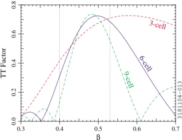
As indicated above, medium-cavities must accelerate a beam whose velocity is varying with position. The pen- alty due to the velocity mismatch can be quantified via the transit time factor (the maximum energy gain for a particle traveling at speed c divided by the energy gain for the ideal case in which the field’s time variation is not ac- counted for and the phase is optimal at every point along the particle’s path). The transit time factor of the g 0:47cavity is shown in Fig. 2 for the 6-cell case and two other cases. The transit time factor was calculated with
SUPERFISH[22,23].
The approximate range of usefulness of the 6-cell cavity is from0:4to0:53(indicated by dotted lines in Fig. 2). The useful range is not determined by the cavity characteristics alone; for RIA as an example, different cavity geometries are used upstream and downstream of the g 0:47cavities, and the useful velocity range for each cavity is determined from the velocities at which one cavity geometry becomes more efficient than another.
The choice of 6 cells is a reasonable compromise be- tween a long structure to provide higher voltage and a small number of cells for higher velocity acceptance.
Note that m is between 0.49 and 0.50 in the 6-cell case, i.e., slightly larger thang; particles withslightly larger thang acquire a little more energy traveling through the cavity and suffer less deceleration from the evanescent field in the beam tube. As can be seen in Fig. 2, the discrepancy between g and m becomes more pro- nounced as the number of cells is reduced.
The beam tube is enlarged on one side of the SNS cavities to provide stronger input coupling. Less coupling is needed for RIA, so no enlargement of the beam tube is
β = 0.47
β = 0.61
β = 0.81β = 1 3180601-001
FIG. 1. (Color) Comparison of theg0:47cell with ag 0:61 cell (SNS), a g0:81 cell (SNS), and a g1 cell (TTF, scaled to 805 MHz).
0.3 0.4 0.5 0.6 0.7
β
0.80.60.40.20.0TT Factor
3-cell
6-cell 9-cell
3181104-013
FIG. 2. (Color) Dependence of the transit time factor on for theg0:47cavity for 3, 6, and 9 cells.
required for theg0:47cavity [24]. This simplifies the cavity fabrication and yields a slight improvement in the rf parameters of the structure. Selected cavity parameters are given in Table I. The accelerating mode is a standing-wave mode, as is the case for most superconducting cavities. In Table I, Ep and Bp are the peak surface electric and magnetic field, respectively; Ra is the shunt impedance (linac definition) and Ea is the accelerating gradient (both include the transit time factor withg). The rf parameters in Table I were calculated with SUPERFISH
[22,23] and checked withSUPERLANS[25].
An analysis was done of the excitation of higher-order modes (HOMs) in the cavity by the beam and coupling of the HOMs to the input coupler and pickup antenna. This analysis indicates that HOM couplers are not required for operation of the g0:47 cavity in RIA, allowing for further simplification of the system [24].
III. SINGLE-CELL CAVITY PROTOTYPING Two single-cell prototypes of theg0:47cavity were fabricated and tested. Some of the results are shown in Fig. 3. The highest gradient reached in the first round of tests [17] was about15 MV=m. As can be seen in Fig. 3, theQ0values at15 MV=mwere about1010; the low-field Q0 values were between 21010 and 41010. These measurements were done at 2 K in a vertical cryostat at Jefferson Lab.
A number of additional tests were done on the second of the two single-cell cavities while commissioning the fa- cilities at MSU for etching, high-pressure rinsing, clean assembly, rf testing, and helium processing of supercon- ducting cavities. The highest gradient reached in these tests was about 18 MV=m, albeit with a slightly lower Q0; nevertheless, Q0 still exceeded 1010 at Ea10 MV=m [18]. As can be seen in Fig. 3, some improvement in the low-fieldQ0 was seen at temperatures below 2 K, but the high-field performance did not change much.
More detailed information on the single-cell results may be found elsewhere [17,18].
IV. MULTICELL CAVITY PROTOTYPING A. Cu cavity
A copper multicell cavity was fabricated to check the procedures for forming and electron beam welding, and to make sure the desired frequency and field flatness could be obtained. Before field flatness tuning, the accelerating mode frequency of the copper model was 805.9 MHz;
the initial electric field unflatness parameter (E=E) was 44%. The field flatness tuning was done using a tuning jig developed for the SNS cavities. The unflatness parameter was 7% after one iteration of flatness tuning. Thus, the initial frequency error was well within the range of the tuning fixture, and the field flatness tuning was not a problem. The copper model was also used for higher-order mode and input coupling measurements [24].
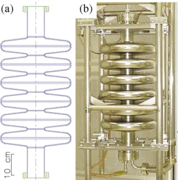
B. Nb cavity fabrication and preparation The results on the copper model being satisfactory, three multicell niobium prototypes were fabricated next. The first 6-cell cavity (Fig. 4) was a simplified version without stiffening rings, dishes for attachment of the helium vessel, or side ports for the rf couplers; these features were in- cluded in the second and third cavities (Fig. 5).
Sheet Nb of thickness 4 mm with nominal residual resistivity ratio (RRR) of 250 was used for all three cav- ities. The forming of half-cells and joining were done by the standard deep drawing and electron beam welding techniques used for elliptical cavities, including SNS pro- totype cavities fabricated at Jefferson Laboratory. As with the SNS cavities, Nb-Ti alloy flanges and Al alloy gaskets were used for the vacuum seal on the beam tubes.
TABLE I. Parameters of the symmetric 6-cellg0:47cav- ity. The rf quantities were calculated withSUPERFISH.
Cell mode TM010
Phase advance per cell
Resonant frequencyf 805 MHz
Cell-to-cell coupling2 ff0= ff0 1.5%
Ep=Ea 3.34
cBp=Ea 1.98
Ra=Q 173
Geometry factorG 136
Active length6gc= 2f 527 mm
Inner diameter at iris (aperture) 77.2 mm
Inner diameter at equator 329 mm
0 5 10 15 20
Ea (MV/m) 10910101011Q0
Cavity, Temperature 1st, 2 K (Jun 2001) 2nd, 2 K (Jun 2001) 2nd, 2 K (Aug 2001) 2nd, 1.5-1.7 K (Aug 2001)
3180204-002
FIG. 3. (Color) Measured dependence of the quality factor on the accelerating gradient for the single-cell cavity prototypes.
The June 2001 measurements were done at Jefferson Lab; the August 2001 measurements were done at MSU. In the June 2001 tests, there may have been some rf conditioning during the measurements, as evidenced by a slight decrease and recovery inQ0at6–7 MV=m(1st cavity) or11–12 MV=m(2nd cavity).
The completed 6-cell cavities were etched with 1:1:1 buffered chemical polishing solution (mixture of concen- trated phosphoric acid, hydrofluoric acid, and nitric acid in equal parts by volume). About100mwas removed from
the inside surface of the first Nb multicell. The cavity was then fired in a vacuum furnace for 10 h at 600C to remove hydrogen and prevent subsequent formation of lossy sur- face hydrides — in other words, to inoculate it against ‘‘Q disease’’ [26]. The pressure in the furnace was106torr during the heat treatment. Field flatness tuning was done next. The final preparation steps were etching of an addi- tional 60m from the inner surface and high-pressure rinsing with ultrapure water in a clean room to remove particulates from the inside surface of the cavity. No vacuum bakeout was done after assembly of the cavity onto the insert.
About 150m was removed during the etch of the second cavity; additional etching was done after the first rf test, as will be described below. About 300m was removed from the third cavity in 2 etching cycles. The second and third cavities were rinsed with high-pressure water, but no firing was done. The third cavity was rinsed twice, as a leak was found in the input coupler port after the first rinse.
C. Tuning
Field flatness tuning was done on all three niobium cavities. The goal was a field unflatness parameter (E=E) of 10% or less. The first cavity was tuned with the SNS tuning jig, as had been done with the copper model. After tuning, E=E was 12%. The tuning was more difficult than it had been with the copper cavity.
The second and third Nb cavities were tuned with a new custom-built jig for the g0:47cavity. This made the tuning easier; with the second Nb cavity,E=E5%was reached in one iteration (see Fig. 6). The results on the third cavity were similar (E=E4:5%).
FIG. 5. (Color) (a) Drawing of the second and third 6-cellg 0:47Nb cavities and (b) photograph of the second cavity. The port for the input coupler can be seen on the left beam tube.
Rings are welded around the outside of the irises to increase the mechanical stiffness of the structure. The end dishes for the attachment of the helium vessel are also visible.
0 5 10 15 20
z (arbitrary units)
43210
Ref −S21 phase (degrees)
untuned tuned
3180204-003
FIG. 6. (Color) Bead pulls for the second 6-cell niobium cavity.
The phase shift (proportional to the square of the electric field) as a function of bead position z was measured with a network analyzer.
FIG. 4. (Color) (a) Drawing of the first 6-cellg0:47cavity and (b) photograph of the cavity on the insert. In (a), Nb parts are in blue and Nb-Ti parts are in green.
V. RF TESTING OF MULTICELL CAVITIES All of the rf tests were done in a vertical cryostat. The residual magnetostatic field inside the cryostat was less than 1T. In all cases, the cryostat was cooled down rapidly to 4.3 K and then pumped to 2 K. The rf power was supplied by a 500 W amplifier; a phase feedback loop was used to make sure that the cavity was always driven on resonance. Copper probe antennas on the beam tube end cap flanges (fixed coupling strength) were used for the input coupler and pickup. A radiation sensor on top of the insert was used to monitor x rays during the rf tests.
Radiation shielding surrounded the cryostat during all rf testing.
A. First test on the first cavity
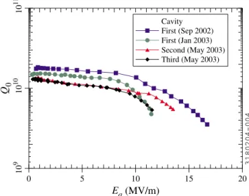
The first vertical rf test was done on the first cavity in September 2002. Figure 7 (squares) shows the measure- ment of the quality factor as a function of field level. As can be seen, the low-fieldQ0 was about21010 andQ0 remained above1010up toEa11 MV=m. A gradient of about16 MV=mwas reached. The test was stopped at that level due to the failure of a rf cable. Some x rays were observed at high field (0:7 rem=h), indicating that the decrease inQ0 at high field was likely due to field emis- sion. Modest rf conditioning (with radiation levels up to 1:2 rem=h) was required to reach a gradient of16 MV=m.
A small leak into the cavity vacuum manifested itself when the cryostat was cooled down; the pressure in the cavity was about106 torrat 2 K.
B. Follow-up tests on the first cavity
The failed rf cable was replaced, the vacuum leak was fixed, and the cavity was retested 1 week after the first rf
test (without exposure of the inside of the cavity to air). A gradient of about 7 MV=m was reached. It was thought that helium processing might be beneficial, but the test had to be stopped early due to scheduled maintenance of the cavity testing facility.
The next opportunity for a rf test was in January 2003. In between tests, the cavity was etched to remove another 50mfrom the inner surface and the high-pressure water rinsing was repeated. The final filter on the high-pressure rinsing system (between the pump and the nozzle) was temporarily unavailable at the time of this rinse.
The results of the January 2003 test are also shown in Fig. 7 (circles). The low-field Q0 was smaller than in the first test, although the difference is within the margin of reproducibility of the measurement. A gradient of about 11 MV=mwas reached. The decrease inQ0between 9 and 11 MV=mis likely due to field emission; the x-ray signals were larger (>1:5 rem=h) than those seen in the first rf test. Thus the difference between the September 2002 and January 2003 tests could be due to particulate contamina- tion during the high-pressure rinse without the final filter.
Although the field level was not as high as in the first test, Q0was nevertheless in excess of1010 atEa8 MV=m.
C. Tests on the second cavity
The second cavity was tested in May 2003. In the first rf test, a gradient of8 MV=mwas reached at 2 K. TheQ0was lower (8109) and someQswitching was seen, indicat- ing that more etching was needed.
In preparation for a second rf test, another150mwas removed from the inner surface, and the high-pressure rinse was repeated. Results from the second test are shown in Fig. 7 (triangles). A gradient of13 MV=mwas reached.
TheQ0 was1010atEa8 MV=m. The field was limited by the available rf power (the input coupling was weaker than planned). The x-ray signals were small (10 mrem=h maximum).
D. Tests on the third cavity
The third cavity was also tested in May 2003. Results are shown in Fig. 7 (diamonds). A gradient of11 MV=mwas reached. The Q0was again about1010 atEa8 MV=m.
The field was again limited by the available rf power (the same weak input antenna was used). As with the second cavity, the x-ray signals were small (0:5 mrem=h maximum).
E. Temperature dependence
Small rf losses in the cavity are desirable to minimize the load to the cryogenic system. Low rf losses correspond to a largeQ0, or, equivalently, a small rf surface resistance Rs, since Q0 G=Rs, where G is the geometry factor.
An approximate expression for the surface resistance of Nb is [26]
0 5 10 15 20
Ea (MV/m)
109 1010 1011Q 0
Cavity First (Sep 2002) First (Jan 2003) Second (May 2003) Third (May 2003)
3180204-004
FIG. 7. (Color) Measured dependence of the quality factor on the accelerating gradient for the 6-cell cavity prototypes. All measurements were done at a bath temperature of 2 K.
Rs T R0CRRRR1T T
f f1
2 exp
T
T
; (1) where T is the temperature, f is the rf frequency, T 17:67 K,R1T 2104K, andf11:5 GHz;R0is the temperature-independent residual surface resistance.
The coefficient CRRR is 1 for reactor grade Nb (RRR 25) and about 1.5 for high purity Nb withRRR250. As the surface purity can be different from the bulk purity, CRRR can be considered to be a fitting parameter.
Equation (1) is valid forf1 THzandT4:6 K.
Figure 8 shows the measured rf surface resistance at low field (Ea0:8 MV=m) as a function of 1=T. The solid lines are calculated from Eq. (1), assuming CRRR1:25 and the indicated R0 values. In all cases, the surface resistance at higher temperatures follows Eq. (1) reason- ably well. This suggests that the surface RRR is smaller than the nominal bulk value of 250, but higher than that of reactor grade Nb. TheRs values at low temperatures are consistent withR0 being between 2 and9 n.
The results for the single-cell cavities were similar to those of the 6-cell cavities. In the best single-cell tests, the temperature-dependent losses were slightly lower than for the 6-cell cavities.
In the January 2003 test on the first 6-cell cavity, mea- surements of Q0 as a function of gradient were done at several different temperatures, as shown in Fig. 9. A sig- nificant downward slope inQ0 can be seen for the mea- surements above the superfluid transition temperature (2.15 K), as is typically seen. Thus, high-field operation of the cavities is more economical forT <2:15 K, as one would expect. The low-field Q0 at 1.8 K is significantly higher than at 2 K, which confirms that the temperature- dependent losses are still contributing to the surface resist-
ance. However, the maximum gradient at 1.8 K is only slightly higher (11:4 MV=m) than at 2 K.
VI. MICROPHONICS AND MULTIPACTING Microphonics are more serious for RIA than for SNS due to the lower RIA beam current. The stiffening rings of the SNS cavities will be used on the g0:47cavity to reduce microphonic excitation (see Fig. 5 above). Lateral bracing similar to the center support ‘‘spider’’ of the SNS cavities [11,27] will also be implemented. The RIA cav- ities will be overcoupled to ensure that the gradient can be maintained in the presence of microphonics [24]. Some microphonic measurements were done on a single-cell cavity [18]. Modeling of vibrations in multicell cavities is in progress. The predictions will be compared with measurements on the 6-cell cavities.
The rf tests on single-cell cavities showed that there are no hard multipacting barriers. A soft multipacting barrier was seen occasionally at very low field (Ea<1 MV=m).
After we introduced gas for He processing, the barrier became more persistent, but we could still punch through it. Multipacting simulations [20,28] also indicate that there should be no hard barriers in the single-cell cavities.
Likewise, no multipacting problems were encountered in the rf tests on the multicell cavities.
VII. CONCLUSION
Encouraging rf test results were obtained for two single- cellg0:47cavity prototypes and three 6-cell cavities:
all of the cavities exceeded the goal of 10 MV=maccel- erating gradient, with Q0 7109 at Ea 10 MV=m and Q0 1010 at Ea8 MV=m. The first 6-cell cavity and both single-cell cavities reachedEa 16 MV=m; the
0.2 0.3 0.4 0.5 0.6 0.7
1/T (K−1)
10−910−810−710−6Rs (Ω)
Cavity
First (Sep 2002) First (Jan 2003) Second (May 2003) Third (May 2003)
R0 = 2 nΩ R0 = 9 nΩ
3180204-005
FIG. 8. (Color) Measured dependence of the rf surface resist- ance on bath temperature for the 6-cell cavity prototypes. The solid lines are theoretical predictions forCRRR1:25andR0 2or9 n.
0 5 10 15 20
Ea (MV/m)
109 1010 1011Q0
T 2.4 K 2.25 K 2.15 K 2.0 K 1.8 K
3180204-006
FIG. 9. (Color) Measured dependence of the quality factor on the accelerating gradient at different bath temperatures for the first 6-cell cavity prototype (January 2003).
second and third 6-cell reached 13 and11 MV=m, respec- tively. The three niobium multicells and one copper multi- cell have been tuned for field flatness. The next step will be a horizontal test of 2 fully equippedg0:47cavities in a prototype cryomodule [29]. Because the input coupling and HOM damping requirements are less stringent, the system will be less complicated than for SNS.
ACKNOWLEDGMENTS
We thank the staff at INFN-Milano, Jefferson Lab, and MSU for their hard work in the design, fabrication, pro- cessing, and testing of the cavity prototypes. R. Afanador, J. Brawley, B. Manus, S. Manning, S. Morgan, G. Slack, and L. Turlington provided essential support with the fabrication and chemical treatment of the cavities at Jefferson Lab. J. Bierwagen, J. Brandon, S. Bricker, J.
Colthorp, S. Hitchcock, M. Johnson, H. Laumer, D.
Lawton, A. McCartney, D. Pedtke, L. Saxton, J. Vincent, and R. Zink provided valuable support at MSU. This work was supported by the U.S. Department of Energy under Grant No. DE-FG02-03ER41247.
[1] H. A. Thiessen, in Proceedings of the 1991 Particle Accelerator Conference, San Francisco, CA, edited by L. Lizama and J. Chew (IEEE, Piscataway, NJ, 1991), pp. 3198– 3200.
[2] W. B. Haynes et al., in Proceedings of the Eighth Workshop on RF Superconductivity, Abano Terme, Italy, 1997, edited by V. Palmieri and A. Lombardi (LNL-INFN Report No. 133/98), pp. 523–533.
[3] K. Saitoet al., inProceedings of the Eighth Workshop on RF Superconductivity, Abano Terme, 1997 (Ref. [2]), pp. 534 –539.
[4] N. Ouchi et al., IEEE Trans. Appl. Supercond. 9, 1030 (1999).
[5] J. L. Biarrotteet al., inProceedings of the 9th Workshop on RF Superconductivity, Los Alamos, NM, 1999(LANL Report No. LA-13782-C, 2000), pp. 384 – 389.
[6] S. Baueret al., inProceedings of the 9th Workshop on RF Superconductivity, Los Alamos, NM, 1999 (Ref. [5]), pp. 443– 445.
[7] N. Akaokaet al., inProceedings of the 9th Workshop on RF Superconductivity, Los Alamos, NM, 1999(Ref. [5]), pp. 450 – 458.
[8] E. Chiaveriet al., inProceedings of the 9th Workshop on RF Superconductivity, Los Alamos, NM, 1999(Ref. [5]), pp. 512 –515.
[9] T. Tajima et al., in Proceedings of the 2001 Particle Accelerator Conference, Chicago, IL, edited by P. Lucas and S. Webber (IEEE, Piscataway, NJ, 2001), pp. 1119–
1121.
[10] C. Pagani et al., in Proceedings of the 2001 Particle Accelerator Conference, Chicago, IL (Ref. [9]), pp. 3612 – 3614.
[11] G. Ciovatiet al., inProceedings of the European Particle Accelerator Conference (EPAC 2002), Paris, 2002, edited by T. Garveyet al.(EPS-IGA and CERN, Geneva, 2002), pp. 2247– 2249.
[12] M. Mizumoto et al., in Proceedings of the XX International Linac Conference, Monterey, CA, edited by A. W. Chao (SLAC Report No. SLAC-R-561, 2000), pp. 566 –568.
[13] C. W. Leemann, in Proceedings of the XX International Linac Conference, Monterey, CA(Ref. [12]), pp. 331–335.
[14] K. W. Shepardet al., inProceedings of the 9th Workshop on RF Superconductivity, Los Alamos, NM, 1999 (Ref. [5]), pp. 345– 351.
[15] K. C. D. Chanet al., inProceedings of the 9th Workshop on RF Superconductivity, Los Alamos, NM, 1999 (Ref. [5]), pp. 465– 471.
[16] A. Facco, in Proceedings of the 11th Workshop on RF Superconductivity, Travemu¨nde, Germany, 2003 (DESY, Hamburg, 2004).
[17] C. C. Comptonet al., inProceedings of the 2001 Particle Accelerator Conference, Chicago, IL(Ref. [9]), pp. 1044 – 1046.
[18] T. Grimmet al., inProceedings of the Tenth Workshop on RF Superconductivity, Tsukuba, 2001, edited by S.
Noguchi (KEK, Tsukuba, Japan, 2003), pp. 86 – 90.
[19] W. Hartung et al., in Proceedings of the 2003 Particle Accelerator Conference, Portland, OR, edited by J. Chew, P. Lucas, and S. Webber (IEEE, Piscataway, NJ, 2003), pp. 1362 –1364.
[20] D. Barni et al., Jefferson Laboratory Technical Note No. JLab-TN-01-014, 2001.
[21] B. Aune et al., Phys. Rev. ST Accel. Beams 3, 092001 (2000).
[22] K. Halbach and R. F. Holsinger, Part. Accel. 7, 213 (1976).
[23] J. H. Billen and L. M. Young, in Proceedings of the 1993 Particle Accelerator Conference, Washington, DC,
edited by
S. T. Corneliussen (IEEE, Piscataway, NJ, 1993), pp. 790 –792.
[24] T. L. Grimm et al., in Proceedings of the European Particle Accelerator Conference (EPAC 2002), Paris, 2002(Ref. [11]), pp. 2241– 2243.
[25] D. G. Myakishev and V. P. Yakovlev, inProceedings of the 1991 Particle Accelerator Conference, San Francisco, CA (Ref. [1]), pp. 3002 – 3004.
[26] H. Padamsee, J. Knobloch, and T. Hays, RF Superconductivity for Accelerators (Wiley, New York, 1998).
[27] J. Hogan et al., in Proceedings of the 2001 Particle Accelerator Conference, Chicago, IL (Ref. [9]), pp. 1158–1159.
[28] W. Hartung, F. Krawczyk, and H. Padamsee, in Proceedings of the Tenth Workshop on RF Superconductivity, Tsukuba, 2001 (Ref. [18]), pp. 627–
631.
[29] T. L. Grimm et al., in Proceedings of the 2003 Particle Accelerator Conference, Portland, OR (Ref. [19]), pp. 1350 –1352.