515 Ceramic Coating in a High-Pressure WtE Steam Generator
Materials and Corrosion
Ceramic Coating in a High-Pressure WtE Steam Generator
– Operational Experience in Zabalgarbi Plant in Bilbao –
Ildefonso Goikoetxea and Eddie Marcarian
1. Zabalgarbi plant ...515
2. Value chain – companies and products involved ...518
3. Product characteristics ...519
4. Description of the last three years test (2014–2017 in progress) ...523
5. Results ...524
6. Conclusions ...526
The Zabalgarbi urban waste-to-energy system is an industrial process that adapts the technology of combined-cycle gas plants to modern waste-to-energy facilities.
This plant has been supplied and delivered in 2005 by a joint venture made by CNIM and SENER.
In order to fulfill with the ambitious plant efficiency, the steam parameters and mainly the pressure value used in the WtE boiler is higher than usually obtained in modern waste-to-energy plants, which cause an increase of corrosion rate on evaporator section.
Conventional protection has been originally installed in the WtE boiler by Inconel 625 application in the first unprotected tiles refractory section.
Despite the satisfactory result demonstrated by the original protection which has been extended afterwards, tests have been made on single tubes using ceramic coating pro- tection developed by Kera-Coat company. Started in 2014, the test is always on going with additional improvement made on material and application technology.
The results obtained are very positive with none corrosion attacks and with positive effect on fouling behavior.
1. Zabalgarbi plant
The Zabalgarbi urban waste-to-energy system is an industrial process that adapts the technology of combined-cycle gas plants to modern waste-to-energy facilities.
Ildefonso Goikoetxea, Eddie Marcarian
516
Materials and Corrosion
It is a single integrated process in which the facilities’ size and features are determined by the following:
• The plant’s required UW treatment capacity.
• Fine-tuning the thermo-electric performance.
• Reducing the environmental impact per kWh generated by the plant.
Figure 1:
Area of WtE integrated in Arti- gas-Arraiz Special Plan in Bilbao
Zabalgarbi occupies a plot measuring just over five hectares within the Artigas-Arraiz Special Plan Area in Bilbao. The industrial facilities cover 2.7 hectares, with the rest being taken up by roads and gardens.
Overall, the Artigas-Arraiz Special Plan Area extends over 108 hectares.
In addition to the urban waste-to-energy plant, it houses a mechanical biological treatment (MBT) plant, a composting facility, a landfill, and a leachate treatment plant.
Zabalgarbi MBT
The Artigas landfill
Composting plant Leachate treatment
plant Artigas
eco-park Figure 2:
Artigas-Arraiz Special Plan Area in Bilbao
General process design features
General concept of the complete process was designed and defined by SENER.
CNIM designed and supplied the incineration line process combined with a Martin type A grate and a Heat Recovery Boiler.
517 Ceramic Coating in a High-Pressure WtE Steam Generator
Materials and Corrosion
In the incineration boiler slight superheated steam at a temperature of 328 °C and a pressure of 106 bar is produced in Zabalgarbi’s incineration-line furnace-boiler. One line with the nominal capacity of the WtE package is 30 t/h of waste for a thermal heat yield of 70.8 MW.
This boiler has an higher pressure than usually obtained in modern waste-to-energy plants (400 °C at 45/60 bar).
Air Fuel
Exhaust gases from the gas turbine
Electric generation
Gas turbine
Superheated steam
Steam turbo- generator
Electric generation
Waste Air
Boiler furnace
Replace-
Waterment Cooling towers Heat recovery
boiler
This saturated steam from the furnace-boiler is superheated to 540 °C in a recovery boiler using heat from the flue gases of a 43 MW gas turbine (GE LM6000), while maintaining pressure at 100 bar in conditions similar to those of a power plant using conventional fuels.
The superheated steam is used to drive a 56.5 MW turbo-generator ( GE Nuovo Pig- none).
Gross power yield is 99.5 MW, and the net output after the plant’s own consumption is 94 MW.
Higher energy yield Today’s state-of-the-art power-generating waste-to-energy (WtE) plants record a net yield of approximately 23 % as average.
However, the Zabalgarbi plant’s innovative design, adapting combined-cycle gas plant technology to modern WtE plants in a single integrated process, permits to reach to a higher efficiency.
The EU’s Thermie Programme – DG 17 – has recognised this improved performance and energy efficiency by granting Zabalgarbi its maximum subsidy for increasing energy performance, saving and efficiency, as well as for reducing its environmental impact.
Saving fossil fuels and reducing CO2 emissions per kWh generated.
The use of UW instead of fossil fuels and its highly efficient plant enable Zabalgarbi to deliver significant primary energy savings.
Figure 3:
Schematic process diagram
Ildefonso Goikoetxea, Eddie Marcarian
518
Materials and Corrosion
Moreover, the renewable fraction of UW entering the plant – biomass – amounts to 63 %, similar to the figures recorded throughout the EU.
This reduction is achieved through the following measures:
• combustion control measures in furnace and burners
• effective scrubbing of combustion gases
• highly efficient technology
• Improved operating conditions reduce corrosion in the furnace-boiler because of the lower temperature of the steam produced, resulting in lower operating and maintenance costs
• Increased plant availability.
• The size of the Zabalgarbi treatment plant combines a processing capacity of around 220,000 to 240,000 t of UW per year with a net installed power-generating capacity of around 95 MW.
2. Value chain – companies and products involved
1. Kera-coat:
Develops, manufactures and supplies tailor made special (high resistance) ceramics (powder/slurry) to be applied on metallic substrates with a world exclusivity agreement for tubular goods to.
2. Tubacoat:
Produces and supplies ceramic coated tubular solutions to the WtE and many other sectors (Power Gen, Chemical, O&G etc.).
3. Zabalgarbi:
WtE plant in Bilbao, pilot tests and end user.
4. CNIM:
Designs, produces and maintains WtE boilers and other systems and applications.
Supply Waste Management solutions.
5. Others (engineering companies, operators, manufactorers, etc.)
Design, production and maintanance in WtE boilers and other systems or other industries.
519 Ceramic Coating in a High-Pressure WtE Steam Generator
Materials and Corrosion
3. Product characteristics
Ceramic coating
0 100micras 0 100micras
Typical coating thickness range: 100 to 200 μm
• Hardness: 64 HRC.
• Elongation: max 1.2 %.
• Roughness: Ra: 0.04 microns; Rz: 0.2 microns.
Figure 4:
Structural view
µm 64 20 -2-4 -6-8
7 8 9 10 11 12 13 14 15 16 Substrate mm
µm
Ceramic coating mm 12 1314 15 16 17 18 19 20 21 22 64
20 -2-4 -6-8 8
Thermal conductivity
0.001 to 0.003 cal./sq. cm./sec/degree C. Despite a certain thermal barrier effect, as the thickness is so small the real effect has demonstrated to be neglectable.
Abrasion resistance
Figure 5:
Coating surface
Mass loss in 10,000 cycles:
Bare Substrate AISI 310: 58 mg Coated AISI 310: 3 mg Figure 6:
Abrasion test
Ildefonso Goikoetxea, Eddie Marcarian
520
Materials and Corrosion
Thermal shock resistance
• Samples are introduced in a furnace during 30’.
• After 30 min. at temperature samples taken from the furnace and directly introdu- ced in a container with cold water 20 °C (68 °F).
• Reached up to 850 °C (1,762 °F) – with no damage, above that temperature, the ceramic starts to soften.
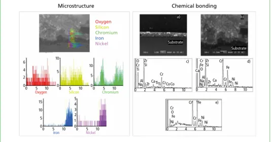
Microstructure and chemical bonding
Figure 8: Softening defects appear at 900 °C Figure 7: Water quenched from 850 °C to 20 °C
Figure 9: Structural analysis
SEM images of inner structure sintered in normal conditions. a) Ceramic coating mi- crograph, b) Micrograph of the interface between the steel substrate and the ceramic coating showing the diffusion area c) Ceramic coating EDX results, d) the interface e) Metal substrate.
This chemical bonding avoids cracks, even in case of impact if the impact effect deforms the substrate above 1.2 % elongation, the ceramic covering the deformed area blows up as powder, but the interface layer remains attached to the substrate. This layer has demonstrated to maintain a better chemical resistance than the substrate.
Oxygen Silicon Chromium Iron Nickel
Iron 0
2 4 6
5 10 0
5 10
Oxygen 0 Silicon5 10
0 0
5 10
5 10
0 Chromium
0 5 10
5 10
0 15
0 1 2
5 10
0 3 4 5
Substrate
a) b)
Substrate
c) d)
e)
2 10
0 4 6 8
CrO Ti
ZrSi
Na ZrAl Ca TiTi
Cr CrCoCo
Ca CrFe O ZrSi
NaAl Cr
Ni Zr Ca Cr Fe
FeNi Ni
2 10
0 4 6 8
2 10
0 4 6 8
Cr O Fe Ni
Cr
Cr Fe
FeNi Ni
Microstructure Chemical bonding
Nickel
Dorfstraße 51 D-16816 Nietwerder-Neuruppin Phone: +49.3391-45.45-0 • Fax +49.3391-45.45-10 E-Mail: tkverlag@vivis.de
TK Verlag Karl Thomé-Kozmiensky
Download Free Articles
waste incineration
photovoltaic
flue gas treatment
balancing and evaluation
bio waste
biogas
biomass
soil steam generator
dismantling
waste incineration
dismantlingwaste incineration
landfill
emission trading
pyrolysis
solid recovered fuels
logistics
district heating, district cooling, process steam
odour
sewage sludge
corrosion and materials
mechanical-biological treatment
mechanical treatment
mineral by-products and wastes
co-incineration
electricity grids
physical- chemical treatment
planning
legislation
recycling
electricity grids
recycling
electricity grids residues
solar thermal energy
recycling
solar thermal energy
recycling energy storage
photovoltaic
energy storage
photovoltaic
drying
turbine and generator underground storage and backfilling of mines
waste generation
fan and stack
gasification
wind power
profitability
HOW DO I FIND RELEVANT ARTICLES?
Alternative 1: Search by topic
If you are looking for articles regarding a specific topic, please go to Fachbeiträge (i.e. free articles, in the top right corner of our homepage). If you select the subcategorie Beiträge you will get complete list of the topics in alphabetical order. Most of them are further divided into sub-themes. Just click on your topic of interest, and you will find the available relevant articles with their bibliographical data. In order to open and download the article, click on the articles title.
Alternative 2: Search by conference
If you are looking for articles regarding a specific conference/congress or book, please go to Fachbücher (i.e. reference books, in the top right corner of our homepage). Here you find a list of the themes, which are covered by our publications.
Choose your field of interest. You will then see all relevant books listed in the order of their release date, starting with the latest publication. The latest publications are recapped under the categorie Neuerscheinungen (i.e. new releases). Once you find the right book, follow the link Inhaltsverzeichnis (i.e. table of content). In order to open and download an article published in the book, click on the articles title.
www. .de
Fachaufsätze_ENG.pdf 1 03.07.17 13:46
www.martingmbh.de
Plant engineering with the environment in mind
Thermal waste treatment plants are complex structures, the design of which differs in each individual case. The implementation of these plants requires a high level of competence in engineering and plant construction covering the whole range of services from planning and supply to start-up and maintenance.
Using our combustion technologies and cooperating with carefully selected and proven suppliers, we have accumulated a vast range of experience as a general contractor for the supply of entire turnkey plants.
In March 2015, we extended our product portfolio. As a plant manufacturer, we use the MARTIN dry digestion system (Thöni technology) to treat organic waste in numerous European countries as well as in Australia and New Zealand.
The Thöni dry digestion system has proven itself and is well established on the market. Biogas, compost and liquid fertilizers are separated from organic wastes and then returned to the material cycle.
MARTIN plants and technologies
„Solutions for the recovery of energy and materials from waste“
C O M B U S T I O N D I G E S T I O N
523 Ceramic Coating in a High-Pressure WtE Steam Generator
Materials and Corrosion
Preferred substrates Vitrification of the ceramic coating requires a 12-minute heat treatment of the tubes at 920 °C for ceramics capable to keep their full properties at 650 °C metal temperature.
This treatment might affect the mechanical properties of some low alloyed steels cur- rently used in WtE boilers.
Austenitic steels do not lose these properties so they are the most preferred to ensure many long years of high efficient performance (AISI 310, 347.).
Advantage:
• Resistance to thermal oxidation/corrosion: Provide both protection of the metal and ease of cleaning.
• Long run Surface metal working temperature: 650 °C with peaks of 850 °C.
• Thermal stability: Ability to withstand intermittent or prolonged heat. (Years).
• Thermal expansion: Designed to be the same as the substrate from: -140 to +850 °C.
4. Description of the last three years test (2014–2017 in progress)
The Wte boiler is a vertical type boiler with convective bundles installed in a third pass. In March 2014 few pieces of about 1m long of coated AISI 310 were inserted in a evaporator panel in the 2nd pass with a metal temperature estimated at about 350 °C (flue gas at 720 ° and steam at 320 °C).
Stack
Emission control
Steam turbine
Transformer yard
Gas turbine Recovered heat boiler
Bag filter
Steam generation Lime scrubber
injection Active carbon injection
Ammonium injection
Combustion control
MSW fed into boiler
cleaningGas
MSW hole
Treated waste outlet
Incine- ration bed Slag outlet outlet Ash
Output to grid Electric power generation Gas cleaning Boiler furnace Reception and mixture Scrap
materials outlet
Figure 10: Schematic boiler view
www.martingmbh.de
Plant engineering with the environment in mind
Thermal waste treatment plants are complex structures, the design of which differs in each individual case. The implementation of these plants requires a high level of competence in engineering and plant construction covering the whole range of services from planning and supply to start-up and maintenance.
Using our combustion technologies and cooperating with carefully selected and proven suppliers, we have accumulated a vast range of experience as a general contractor for the supply of entire turnkey plants.
In March 2015, we extended our product portfolio. As a plant manufacturer, we use the MARTIN dry digestion system (Thöni technology) to treat organic waste in numerous European countries as well as in Australia and New Zealand.
The Thöni dry digestion system has proven itself and is well established on the market. Biogas, compost and liquid fertilizers are separated from organic wastes and then returned to the material cycle.
MARTIN plants and technologies
„Solutions for the recovery of energy and materials from waste“
C O M B U S T I O N D I G E S T I O N
Ildefonso Goikoetxea, Eddie Marcarian
524
Materials and Corrosion
5. Results
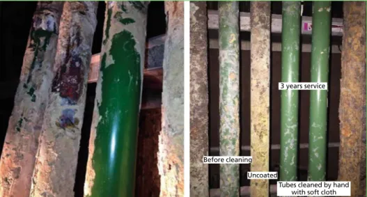
After one-year operation, the tubes were always brand new; ash was easily removed by hand as it was probably deposited by condensation at the cooling of the boiler and not in hot operation. The glossy surface indicates that not a single micron of coating has been neither eroded nor corroded during the year. The same still happens after three years operation.
Figure 11:
Tubes coating aspect
Before cleaning Uncoated
3 years service
Tubes cleaned by hand with soft cloth
Figure 12: Tubes after one year and after three years before and after cleaning the ash by hand with a glove
525 Ceramic Coating in a High-Pressure WtE Steam Generator
Materials and Corrosion
During these three years of practice it has been developed some ancillary.
Processes that are building up a full-coated solution for existing and new boilers such the ones described below:
These covers resist perfectly the burning particles thrown away by grinding discs or during welding.
They also resist conventional shot blasting aimed for bare steel tubes.
Ceramic-coated tubes can be easily cleaned by water jet.
Actually the black fasteners are not needed as the plastic cover shrinks against the tube, plastic covers are longitudinally open and can be easily be folded and unfolded on the tubes, by hand.
Figure 13:
Plastic protection covers for shop and inside boiler operations
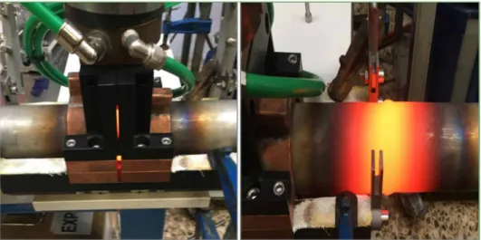
Figure 14: On site coating and vitrification of welded joints and eventual defects
The heating system based on induction technology is under development and final tuning is expected end September 2017.
Ildefonso Goikoetxea, Eddie Marcarian
526
Materials and Corrosion
6. Conclusions
The three years test in WtE boiler in Bilbao allow to conclude:
• Excellent corrosion resistance.
• Excellent coat bonding under thermal stress.
• Homogeneous performance.
• Very low ash adherence to outer surface.
• After 3 years can be estimated a long life.
• Reduces cleaning and maintenance.
• Improves boiler thermal efficiency.
Potential possible applications
Possible application on superheated part (higher metal temperature)
Once the ceramic application can be spread in different parts into the WtE not only in boilers, other exchangers, parts affected by corrosion, or a first full-coated boiler can start operating, it will be able to see and evaluate if the expected efficiency gain due to less ash deposition and less tube degradation might allow to design boilers working a) at higher steam temperature; reducing the boiler size for the same output; with lower maintenance costs, etc.
If this more optimised operation of the boiler is confirmed, there will be an automatic increase of efficiency just by avoiding the loss due to ash fouling.
This principle might apply to the whole boiler including the economizer passes and other parts like ducts, bag house filter, etc. Also to progress in complete water walls and panels with ceramic coating up to 12 m long x 2,5 m width.
Other potential applications in WtE plans and industry
• All types of bent tube, tube-sheet and other type of hear recovery exchangers, eco- nomizers, etc.
• Combustion grate parts coated to prevent high temperature abrasion-corrosion.
• Scrubber lining sheets and ducts.
• Pilot flue gas condensers capturing some gases at economizer outlet: to be tested this winter at the same Bilbao site. (A 5 Kw prototype has been successfully tested with gases after bag house filter).
• The target of this new heat exchanger made of internally ceramic coated carbon steel tubes is:
* Observe evolution of emissions decreasing (SOx, NOx, etc.) by condensing the fumes down to 30 °C.
527 Ceramic Coating in a High-Pressure WtE Steam Generator
Materials and Corrosion
* Observe reduction of particles content through the condensed water along the narrow tubes catching the flying particles and drain them down to the collecting tank for condensates.
* Study potential internal applications of fumes after the exchanger (sensible heat might be used to generate electricity via ORC, district heating or cooling, etc.
* Study quality of condensates for water recovery and treatment design; a big amount of condensed water could be recover, reducing water consumption.
Vorwort
4
Bibliografische Information der Deutschen Nationalbibliothek Die Deutsche Nationalbibliothek verzeichnet diese Publikation in der Deutschen Nationalbibliografie; detaillierte bibliografische Daten sind im Internet über http://dnb.dnb.de abrufbar
Thomé-Kozmiensky, K. J.; Thiel, S.; Thomé-Kozmiensky, E.;
Winter, F.; Juchelková, D. (Eds.): Waste Management, Volume 7 – Waste-to-Energy – ISBN 978-3-944310-37-4 TK Verlag Karl Thomé-Kozmiensky
Copyright: Elisabeth Thomé-Kozmiensky, M.Sc., Dr.-Ing. Stephanie Thiel All rights reserved
Publisher: TK Verlag Karl Thomé-Kozmiensky • Neuruppin 2017
Editorial office: Dr.-Ing. Stephanie Thiel, Elisabeth Thomé-Kozmiensky, M. Sc.
Janin Burbott-Seidel and Claudia Naumann-Deppe
Layout: Sandra Peters, Anne Kuhlo, Ginette Teske, Claudia Naumann-Deppe, Janin Burbott-Seidel, Gabi Spiegel and Cordula Müller
Printing: Universal Medien GmbH, Munich
This work is protected by copyright. The rights founded by this, particularly those of translation, reprinting, lecturing, extraction of illustrations and tables, broadcasting, micro- filming or reproduction by other means and storing in a retrieval system, remain reserved, even for exploitation only of excerpts. Reproduction of this work or of part of this work, also in individual cases, is only permissible within the limits of the legal provisions of the copyright law of the Federal Republic of Germany from 9 September 1965 in the currently valid revision. There is a fundamental duty to pay for this. Infringements are subject to the penal provisions of the copyright law.
The repeating of commonly used names, trade names, goods descriptions etc. in this work does not permit, even without specific mention, the assumption that such names are to be considered free under the terms of the law concerning goods descriptions and trade mark protection and can thus be used by anyone.
Should reference be made in this work, directly or indirectly, to laws, regulations or guide- lines, e.g. DIN, VDI, VDE, VGB, or these are quoted from, then the publisher cannot ac- cept any guarantee for correctness, completeness or currency. It is recommended to refer to the complete regulations or guidelines in their currently valid versions if required for ones own work.