Materials and Corrosion
Ceramic Coating of Superheater Tubes and Extended Experiences in WtE Boilers as Alternative to Nickel-based Protection
Ildefonso Goikoetxea and Eddie Marcarian
1. Product characteristics ...476
2. Value chain – companies and products involved ...480
3. Zabalgarbi plant update ...480
3.1. General information ...480
3.2. General process design features ...481
3.3. Description of the last years test (2014-2018 in progress) ...482
3.4. Results ...483
4. Stoke-on-Trent boiler ...484
4.1. General information ...484
4.2. Test performed ...484
4.3. Results ...487
4.4. Laboratory test ...488
4.5. Coating quality ...494
4.6. Conclusion ...494
5. To go further: other tests and perspectives ...494
6. Conclusions ...496
7. Sources ...497
The Zabalgarbi urban waste-to-energy plant is an industrial process that adapts the technology of combined-cycle gas plants to modern waste-to-energy facilities in a single integrated process. The configuration contains a vertical boiler of 30 t/h of capacity. In 2014, it has been decided to introduce some experiences with a new different overlay application in hot areas. This idea has permitted to perform some test of ceramic coating protection on evaporator tubes parts which had been already presented by the authors [2].
Materials and Corrosion
After one year more of operation, the conservation of the ceramics is successful, also the installing tubes with different ceramic composition for different temperature ran- ges. Zabalgarbi is also trying to look for experience of these ceramics in grate bars and other potential areas affected by erosion and/or corrosion.
CNIM has been participating in these experiences by assisting on technical issues related to the boiler.
Considering the good result obtained with the Bilbao boiler test, it has been decided to go over, and to test this coating in more severe condition. For this purpose, some ceramic coating tubes have been installed in the Stoke-on-Trent (United Kingdom) boiler where Nickel based protection has a short life duration.
The Stoke-on-Trent boiler is equipped with platen superheaters located in hot flue gas temperature, and is exposed to a high corrosion rate.
The results of three years of field tests have shown up some draw backs to bear in mind and feed back to optimize the industrial process under construction, however they were encouraging to continue research, identify potential application limits and – equally important – to further develop the coating process itself.
In this respect, the test program has been extended, applying the coating as well to other parts usually suffering from short life time due to high corrosion rates.
1. Product characteristics
Ceramic coated tubes are supplied by Tubacoat (Tubacex Group), where the design of the ceramic coatings is made by Kera-Coat.
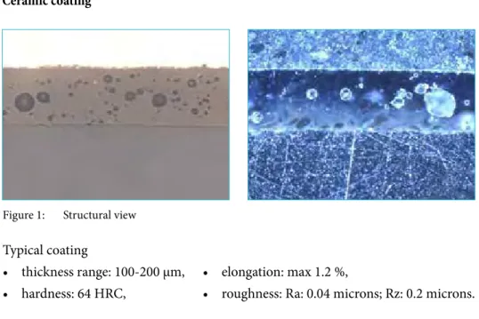
Ceramic coating
Figure 1: Structural view Typical coating
• thickness range: 100-200 μm,
• hardness: 64 HRC,
• elongation: max 1.2 %,
• roughness: Ra: 0.04 microns; Rz: 0.2 microns.
Materials and Corrosion
• Thermal conductivity: 6 Watt/mK at 600 °C
Abrasion resistance
Figure 3: Abrasion test
Thermal shock resistance
• Samples are introduced in a furnace during 30 minutes.
• After 30 min. at temperature samples taken from the furnace and directly introdu- ced in a container with cold water 20 °C (68 °F).
• Reached up to 850 °C (1,762 °F) – with no damage, above that temperature, the ceramic starts to soften.
Mass loss in 10,000 cycles:
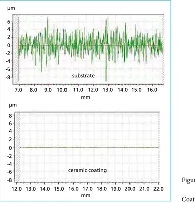
Bare Substrate AISI 310: 58 mg Coated AISI 310: 3 mg substrate
mm µm
-8 -6 -4 -2 0 2 4 6
7.0 8.0 9.0 10.0 11.0 12.0 13.0 14.0 15.0 16.0 µm
-8 8
-6 -4 -2 0 2 4 6
mm
12.0 13.0 14.0 15.0 16.0 17.0 18.0 19.0 20.0 21.0 22.0 ceramic coating
Figure 2:
Coating surface
Materials and Corrosion
Chemical Bonding
Oxygen Silicon Chromium IronNickel
Oxygen Silicon Chromium
Iron Nickel
substrate
substrate
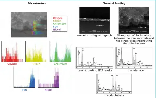
ceramic coating micrograph Micrograph of the interface between the steel substrate and
the ceramic coating showing the diffusion area
metal substrate
0 2 4 6 8 10
Fe Fe
Ni Ni Cr
O Fe Ni
Cr
Cr
Microstructure
O CR Ti
NaAl ZrCa
Co Co TiTi
Cr Cr
0 2 4 6 8 10 0 2 4 6 8 10
Ar
Si Cr
Fe
NiNaAl ZrCa CaO
Cr
CrFe Fe
Ni Ni
the interface ceramic coating EDX results
Microstructure and chemical bonding
This chemical bonding avoids cracks, even in case of impact. If the impact effect deforms the substrate above 1.2 % elongation, the ceramic covering of the deformed area blows up as powder, but the interface layer remains attached to the substrate. This layer has demonstrated to maintain a better chemical resistance than the substrate.
Figure 4: Water quenched from 850 °C
to 20 °C (metal temperature) Figure 5: Softening defects appear at 900 °C (metal temperature)
Figure 6: Structural analysis – SEM images with EDX results (sintered in normal conditions)
Preferred substrates
• Vitrification of the ceramic coating requires a 12-minute heat treatment of the tubes in the range of 700-1,000ºC for ceramics capable to keep their full properties at 650 °C metal temperature.
• This treatment might affect the mechanical properties of some low alloyed steels currently used in WtE boilers.
• Austenitic steels do not lose these properties so they are the most preferred to ensure many long years of high efficient performance (AISI 310, 347).
Materials and Corrosion
Advantage
• Resistance to thermal oxidation/corrosion: Provide both protection of the metal and ease of cleaning.
• Long run surface metal working temperature: 650 °C with peaks of 850 °C.
• Thermal stabilty: Ability to withstand intermittent or prolonged heat (years).
• Thermal expansion: Designed to be the same as the substrate from –140 to +850 °C.
Figure 7: Tubes plastic protection
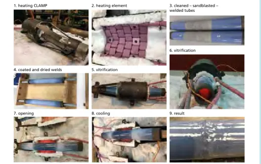
On site coating and vitrification of welded joints and eventual defects
1. heating CLAMP 2. heating element 3. cleaned – sandblasted –
welded tubes
4. coated and dried welds 5. vitrification
6. vitrification
7. opening 8. cooling 9. result
Figure 8: Weld treatment – on site coating and vitrification of welded joints and eventual defects It has been developed some ancillary pro- cesses that are building up a full-coated solution for existing and new boilers such the ones described below.
Plastic protection covers for shop and inside boiler operations These covers resist perfectly the burning particles thrown away by grinding discs or during welding. They also resist conven- tional shot blasting aimed for bare steel tubes. Ceramic-coated tubes can be easily cleaned by water jet.
Materials and Corrosion
2. Value chain – companies and products involved
1. Kera-Coat
Develops, manufactures and supplies tailor made special (high resistance) cera- mics (powder /slurry) to be applied on metallic substrates with a world exclusivity agreement for tubular goods to.
2. Tubacoat
Produces and supplies Ceramic coated tubular solutions to the WtE and many other sectors (Power Gen, Chemical, O&G etc.).
3. Zabalgarbi
WtE plant in Bilbao, pilot tests and end user.
4. CNIM
Designs, produces and maintains WtE boilers and other systems and applications.
Supply waste management solutions.
5. Others (engineering companies, operators, manufactorers etc.)
Design, production and maintanance in WtE boilers and other systems or other industries.
3. Zabalgarbi plant update 3.1. General information
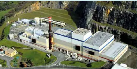
The Zabalgarbi urban waste-to-energy system is an industrial process that adapts the technology of combined-cycle gas plants to modern waste-to-energy facilities. The plant has been supplied and delivered in 2005.
Figure 9: Area of WtE integrated in Artigas-Arraiz Special Plan in Bilbao
Materials and Corrosion
It is a single integrated process in which the facilities’ size and features are determined by the following:
• the plant’s required urban waste treatment capacity,
• fine-tuning the thermo-electric performance, and
• reducing the environmental impact per kWh generated by the plant.
3.2. General process design features
General concept of the complete process was designed and defined by SENER. CNIM designed and supplied the incineration line process combined with a Martin type A grate and a heat recovery boiler.
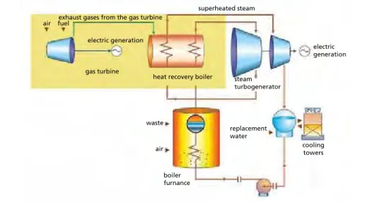
In the incineration boiler slight superheated steam at a temperature of 328 °C and a pressure of 106 bar is produced in Zabalgarbi’s incineration-line furnace-boiler. One line with the nominal capacity of the WtE package is 30 t/h of waste for a thermal heat yield of 70,8 MW.
This boiler has an higher pressure than usually obtained in modern waste-to-energy plants (400 °C at 45/60 bar).
air
air fuel
electric generation exhaust gases from the gas turbine
superheated steam
steam turbogenerator
waste
replacement water
electric generation
cooling towers
boiler furnance heat recovery boiler gas turbine
Figure 10: Schematic process diagram
This saturated steam from the furnace-boiler is superheated to 540 °C in a recovery boiler using heat from the flue gases of a 43 MW gas turbine (GE LM6000), while maintaining pressure at 100 bar in conditions similar to those of a power plant using conventional fuels.
The superheated steam is used to drive a 56.5 MW turbo-generator (GE Nuovo Pi- gnone). Gross power yield is 99.5 MW, and the net output after the plant’s own con- sumption is 94 MW.
Materials and Corrosion
3.3. Description of the last years test (2014-2018 in progress)
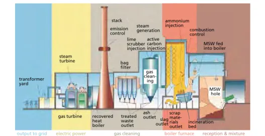
The WtE boiler is a vertical type boiler with convective bundles installed in a third pass. In March 2014 few pieces of about 1 m long of coated AISI 310 were inserted in a evaporator panel in the 2nd pass with a metal temperature estimated at about 350 °C (flue gas at 720 °C and steam at 320 °C).
output to grid electric power
generation gas cleaning boiler furnace reception & mixture gas turbine recovered
heatboiler
treated waste outlet
ash outlet scrap mate- rials
outlet incineration bed outletslag
clean-gas transformer ing
yard
steam turbine
stack emission control
bagfilter lime scrubber injection
active carbon injection steam generation
ammonium injection
combustion control
MSW fed into boiler
MSW hole
Figure 11: Schematic boiler view
Figure 12:
Tubes coating aspect of ceramic application on site (welding parts)
Materials and Corrosion
3.4. Results
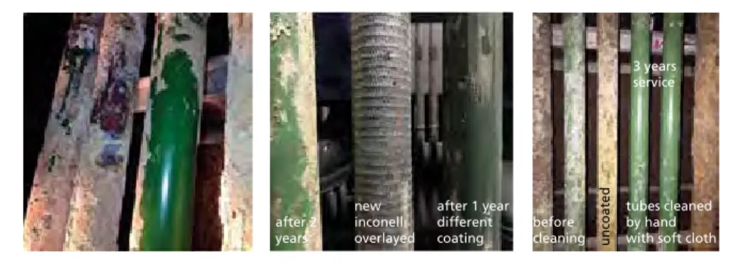
After one-year operation, the tubes were always brand new; ash was easily removed by hand as it was probably deposited by condensation at the cooling of the boiler and not in hot operation. The glossy surface indicates that not a single micron of coating has been neither eroded nor corroded during the year. The same still happens after three years operation.
after 1 year different coating new
inconell overlayed after 2
years before
cleaning uncoated 3 years service
tubes cleaned by hand with soft cloth
Figure 13: Tubes after one year and after three years before and after cleaning the ash by hand with a glove
After four years (results for 2018) The results are always satisfactory without losing material and without any thickness reduction. Nevertheless, it was detected that sand blasting done last year (2017) without protecting tubes is harmful for the coating.
Figure 14: Tubes after four years with different ceramic quality after cleaning and some attacked tubes due to sand blasting last year without cover
According the good result of these four years, Zabalgarbi is evaluating the possibility to extend the use of the ceramic coating to half of a panel in near future.
Other potential application in evaluation by Zabalgarbi are the application of ceramic coating in water wall behind the refractory tiles in the furnace.
Materials and Corrosion
4. Stoke-on-Trent boiler 4.1. General information
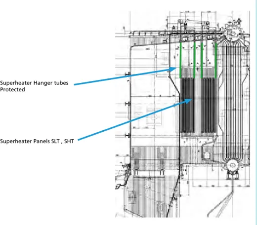
The Stoke-on-Trent plant is equipped with two boilers in operation since 1997 for a waste throughput of 13 t/h each. The vertical boilers are equipped with panels su- perheater located in the second pass. For some years, the superheaters suffer a lot of corrosion attack with a life duration around two years. The boiler produces steam at 46 bar and 395 °C.
4.2. Test performed
The intention is to install some ceramic coated tubes as hanger tubes. Indeed, these tubes are originally protected by SiC tiles. Some previous tests done using Alloy 625 coating demonstrated a quick (< two years) corrosion of these tubes. It should be an interesting advantage to find a resistant coating for these tubes, as Alloy 625 is not adequate and SiC tiles require maintenance.
Figure 15: Stoke-on-Trent boiler – superheater panels and intended ceramic coated hanger tubes Superheater Hanger tubes
Protected
Superheater Panels SLT , SHT
CNIM - 35, rue de Bassano - 75008 Paris - France
Leeds (UK)
Energy-from-Waste plant 160.000t/a Image courtesy of Thomas Graham - Arup
09/2018 - Agence Huitième Jour
A RENEWABLE
SOURCE OF ENERGY Turnkey design & build and services
For:
Household waste
Commercial and industrial waste Biomass
Fuels derived from waste
To produce:
Recyclable materials Compost
Energy (heat and electricity)
Materials and Corrosion
4.3. Results
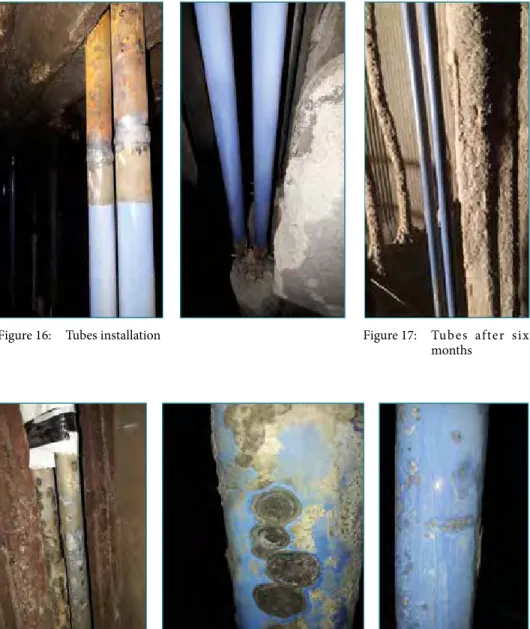
After six months of continuous operation, the result seem very interesting, as no fouling was stuck on the tubes, and the coating was brand new.
After one year of operation, it was finally possible to enter in the boiler and inspect the coated tubes.
Figure 18: Tubes after one year with attack signs
Figure 16: Tubes installation Figure 17: Tubes after six
months
Materials and Corrosion
4.4. Laboratory test
In order to have a better understanding of the phenomena, Energy Dispersive X-Ray Spec- troscopy (EDS) was used to know the composition of the deposits found over the coating layer analyzed in Figure 19. In this area, the corrosion products are rich in Cl, K, Na and S.
Spectrum C O Na Al Si S Cl K Ca Ti Mn Co Zr
norm. wt-%
P 6227 4.44 10.08 3.30 - 15.03 0.74 32.33 34.07 - - - - - P 6228 9.91 13.82 4.01 - 3.17 5.74 27.43 35.93 - - - - - P 6229 - 48.95 4.00 2.47 28.25 - 0.75 5.52 0.95 2.60 0.60 1.17 4.74 Figure 19: EDS results of the deposits over the coating layer
EDS Mappings were performed in several pits with corrosion deposits to determine the concentration of several elements like Cl, Na, K, S etc. It is supposed that localized corrosion is caused by sulfidation/oxidation and/or chlorination attacks.
O-K Cr-Ka
Fe-KA N-L S-KA
Na-K
Figure 20: EDS Mapping of corrosion products rich in Na and S
20 µm EHT = 10.00 kV 10 µm
WD = 8.7 mm
Signal A = AsB Mag = 300 X width = 381.1 µm
EHT = 15.00 kV WD = 8.7 mm
Signal A = AsB Mag = 750 X width = 152.4 µm
Materials and Corrosion
In Figure 20, different layers/compounds have been detected: on top, Iron rich com- pound, and consequently Ni and S, then a Chromium rich oxide and finally a Na rich compound.
In other analyzed area (Figure 21), again Cr oxides and Fe-Ni-S are present but instead of Na rich compounds, Cl and K have been detected.
O-K Cr-KA
S-KA Ni-L
Fe-KA
Cl-KA K-KA
Figure 21: EDS Mapping of corrosion products rich in Cl, K and S
The received tubes presented two types of deposits. On one hand, it was observed that some areas present small lentils or solid balls, well stuck onto the surface. These lentils were removed and a compositional analysis was made in both sides, one labeled as black side and the other one as brown side. On the other hand, the received tubes were covered with a kind of white dust or ashes in some areas and these were also characterized.
In conclusion, localized corrosion has been observed with several pittings with corrosion deposits over them. The austenitic stainless steel has been suffered from this corrosion mode with intergranular precipitation of Chromium Carbides. Corrosion deposits, rich in Cl, K, Na and S have been observed on the surface of the coating.
This localized corrosion could have started in zones where coating have been spalled or cracked.
Materials and Corrosion
Laboratory ash corrosion test
It seems that the elements K, Cl, Na and S are well present in all the corroded areas, but also Pb. Probably these elements form different compounds of low melting point, which adhere to the coated surface of the tubes destroying the enamel layer and atta- cking the stainless steel.
To support this hypothesis, Tubacoat asked KeraCoat to carry out a laboratory test using the real white ashes and lentils that were attached to the samples.
A small amount of white ashes and lentil milled ashes, were placed over the surface of one uncoated stainless steel plate and one coated plate (Figure 22).
XRF
Element Solid lentil White ash Brown side Black side Zone 1 Zone 2 Zone 3 Fe 10.92 4.3 0.42 1.51 1.84 K 5.68 10.73 2.51 7.42 7.43 S 8.46 13.08 11.34 13.14 20.05 Pb 0.95 0.34 0.73 1.27 1.29 Zn 1.01 0.75 0.38 1.03 0.96 Cr 46.15 2.72 0.02 0.08 0.06 Ni 9.57 0.79 - 0.06 - Br 0.19 0.06 0.01 0.01 - Cd 0.18 - 0.01 0.06 0.05 Mo 0.36 - - 0.02 0.03 Cl 13.02 11.43 4.62 6.49 7.42 Ca 0.63 3.39 1.11 4.84 4.1
w 0.71 0.03 - - -
Si 0.92 11.54 28.21 - 56.2 Cu 0.19 0.08 0.05 0.06 Al 0.96 9.54 6.82 - - Ti 0.1 0.11 0.11 0.22 0.67 Na - 31.11 43.66 63.79 -
Table 1:
EDS results of XRF analysis over solid lentils and white ashes
stainless steel uncoated plate coated plate
Figure 22:
Stainless steel uncoated and coated plates before the labo- ratory test
Materials and Corrosion
These plates were placed inside a furnace for one hour (Figure 23). As a result, the uncoated sample presents a chemical attack and weight loss, and the coated one expe- rienced an slight attack with only loss on brightness.
Figure 23:
Uncoated and coated plates after 1 hour at 600 °C in a laboratory furnace
Figure 24:
Uncoated and coated plates after 96 hours at 600 °C in a labora- tory furnace
stainless steel uncoated plate coated plate
After 96 hours (Figure 24), stainless steel presents a significant weight loss and a change in color and a loss on brightness can be observed in the coated sample.
stainless steel uncoated plate coated plate
After 150 hours (Figure 25), an important attack is observed for stainless steel but it can be observed how the ashes begin to remain attached to the coated surface.
stainless steel uncoated plate coated plate
Figure 25:
Uncoated and coated plates after 150 hours at 600 °C in a laboratory furnace
Materials and Corrosion
4.5. Coating quality (handicraft)
The coating process is developing to an industrial quality, and it has been noticed that the test tubes was done as R&D samples by:
Figure 26: Crack or spalling on ceramic coating
• handling by hand (marks),
• spraying by hand – very irregular coat thick- ness (only 20 microns for some parts),
• dust in the ambiance (sticken dust creates worm holes to the substrate and was the in- itiation of the pitting corrosion (the black dots) apart from scratches and other hand- ling defects), and
• inadequate furnace (vitrified 200 Kgs of tube (12 min) in a furnace designed to quench 40 Mt during 20 hours).
These tubes showed coating thickness variations and black dots, mainly coming from floating dust of sand and oxides in a big cast Iron foundry shop.
Better results are foreseen in the new set of samples being prepared by Tubacoat as ceramic layer homogeneity and dust control will be controlled through the new ma- nufacturing line and control process.
4.6. Conclusion
It can be concluded that:
• Corrosion started after six months once ashes got sticked on the tube surfaces.
Adherence therefore has been identified as a relevant property against corrossion
• Characterized tubes have suffered from localized corrosion, probably due to the formation of low melting point compounds based on mainly Na, K, Cl, S and Pb elements and been close to the softening point of the enamel layer.
• If the coating layer presents a pin hole or a spalling and if these elements diffuses into the stainless steel surface, then corrosion reactions can be accelerated and as a result important pits are formed.
• A taylor made ceramic will be prepared to stand the ashes composition
5. To go further: other tests and perspectives
Test on sootblower lance
The life duration of the lances located in hot flue gas area is sensitive. The installation of long retractable sootblowers is an issue in regards of the plant layout.
Materials and Corrosion
New tests should be done in Stoke-on-Trent plant or Wolverhampton plant where lance life duration is limited to six months.
Test on grate bars
This test is performed in Zabalgarbi plant.
Figure 27: Grate bars application
Flue gas condenser With very positive result for corrosion issues applying ceramic coating in internal tubes, a condenser prototype with fumes after the bag house filter has been tested in Zabalgarbi plant.
Figure 28 shows the design of the condenser.
Figure 28: 5 kW fume condenser prototype at an urban waste power plant
Materials and Corrosion
A 5 kW prototype has been successfully tested in Zabalgarbi with gases after bag house filter. The target of this new heat exchanger made of internally ceramic coated carbon steel tubes has been to:
• observe tubes behaviour with ceramic coating,
• observe reduction of chemical compounds and particles,
• study potential internal applications of sensible heat, and
• study quality and quantification of condensates for water recovery and treatment design reducing water consumption.
After six moth working in real conditions, the aspect of the tubes coated and bare are shown in Figure 29.
Figure 29: Coated/non coated elements from
the condenser Figure 30: Turbulators were placed inside the tubes to enhance turbulence
6. Conclusions
Zabalgarbi WtE plant – Spain
The four years test in WtE boiler in Bilbao allows to conclude:
• excellent corrosion resistance,
• excellent coat bonding under thermal stress,
• homogeneous performance,
• very low ash adherence to outer surface,
• after four years can be estimated a long life,
• reduces cleaning and maintenance, and
• tests have shown the sensitiveness to blasting.
Stoke-on-Trent WtE plant – UK
The test in WtE boiler in Stoke allows to conclude:
• very low ash adherence to outer surface,
Materials and Corrosion
• Tubacoat solution raises as a potential solution for improving heat exchange sur- faces in high corrosion areas of the boiler where before it was not possible. Further analysis, are required for concluding.
• The homogeneity of the ceramic layer on the tube surface is key to protect the tubes from corrosion. This property is expected to be solved by coating process fully controlled.
• During the test, Tubacoat obtained the best corrosion properties among all solutions tested.
• New test with high quality coating must be repeated.
Other potential applications in WtE plants and industry:
• sootblower lance,
• all types of bent tube, tube-sheet and other type of heat recovery exchangers, eco- nomizers, etc.
• combustion grate parts coated to prevent high temperature abrasion-corrosion,
• scrubber/bag filter lining sheets and ducts,
• flue gas condensers capturing some gases at economizer outlet or after bag house filter in order to recover heat from gases and/or to reduce chemical compounds or recover water for reuse.
7. Sources
[1] Erana, Ruben (Tubacoat)
[2] Goikoetxea, I.; Marcarian, E.: Ceramic Coating in a High-Pressure WtE Steam Generator – Ope- rational Experience in Zabalgarbi Plant in Bilbao. In: Thomé-Kozmiensky, K. J. et al. (Eds.): Waste Management, Volume 7. Neuruppin: TK Verlag Karl Thomé-Kozmiensky, 2017, pp. 515-527 [3] Vergara, Jose Maria (Kera-Coat)
Contact Person
Eddie Marcarian CNIM Group
Head of Department Chaudières et Combustion 35, rue de Bassano
75008 Paris FRANCE
Phone: 0034 - 4-94103308 Email: emarcarian@cnim.com
Other Institutions
Zabalgarbi, S.A.
As your expert for refractories we create innovative solutions for all industries. For more than 80 years.
Worldwide. The closeness to our customers has made us strong. We focus on the specific requirements of our business partners and provide customized complete solutions. We do not know any limits in Refracotries. In this sense we are always willing to be at your service.
in Waste-to-Energy
Thermische Anlagen Bazenheid, Switzerland Refractory Lining Boiler 1