1
Computation exercise 3(a): Control design
Mechatronic systems 376.050
2016W Important: Answers must be a hard copy and submitted to the office in CA0421 by 20th of December, 2016 at 4pm. The work must be original.
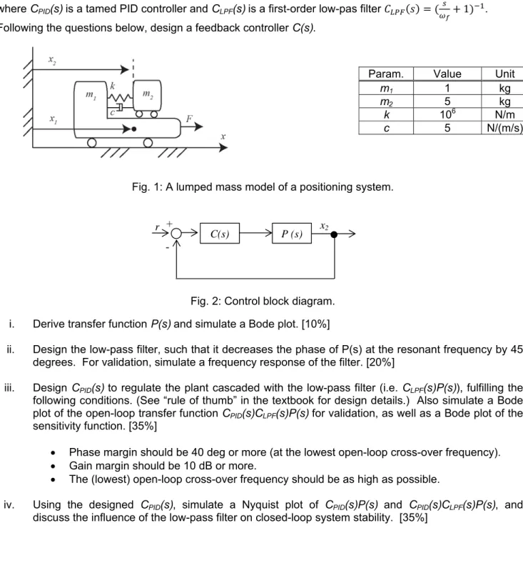
Fig. 1 shows a lumped mass model of a positioning system using a Lorentz actuator. Fig. 2 shows a control block diagram to regulate the position x2 by using the system input F, where P(s) is the plant. The transfer function C(s) is a controller and has the following structure:
,
where CPID(s) is a tamed PID controller and CLPF(s) is a first-order low-pas filter 1 . Following the questions below, design a feedback controller C(s).
Param. Value Unit
m1 1 kg
m2 5 kg
k 106 N/m
c 5 N/(m/s)
Fig. 1: A lumped mass model of a positioning system.
Fig. 2: Control block diagram.
i. Derive transfer function P(s) and simulate a Bode plot. [10%]
ii. Design the low-pass filter, such that it decreases the phase of P(s) at the resonant frequency by 45 degrees. For validation, simulate a frequency response of the filter. [20%]
iii. Design CPID(s) to regulate the plant cascaded with the low-pass filter (i.e. CLPF(s)P(s)), fulfilling the following conditions. (See “rule of thumb” in the textbook for design details.) Also simulate a Bode plot of the open-loop transfer function CPID(s)CLPF(s)P(s) for validation, as well as a Bode plot of the sensitivity function. [35%]
Phase margin should be 40 deg or more (at the lowest open-loop cross-over frequency).
Gain margin should be 10 dB or more.
The (lowest) open-loop cross-over frequency should be as high as possible.
iv. Using the designed CPID(s), simulate a Nyquist plot of CPID(s)P(s) and CPID(s)CLPF(s)P(s), and discuss the influence of the low-pass filter on closed-loop system stability. [35%]
C(s) P (s)
+ -
r x2