Chapter 2
Geometric optics and the basic working of telescopes
Armed with our simple picture of “light as particles moving along straight lines” we can now investigate what happens if this light enters a mirror telescope. And with just a slight allusion to the wave nature of light we can also include the effect of lenses: The breaking of light on surfaces of changing refractive index. We will, however, postpone the more complex wave-related telescope phenomena until Chapter 3.
Literature:
The book by Smith, King & Wilkins, “Optics and Photonics, An Introduction” Second Edition, 2007, John Wiley and Sons, ISBN 9780470017845. An excellent introduction to the topic at a university student level.
Born & Wolf, “Principles of Optics”, 1959, 2002, Press Syndicate of the Univeristy of Cambridge, ISBN 0521642221. A classic.
L´ena, Lebrun & Mignard, “Observational Astrophysics”, 2nd Edition, 1998, Springer-Berlin, ISBN 3540634827.
Broad overview of the topic, though more for advanced reading.
Schroeder, “Astronomical Optics”, 1999, ISBN 0126298106
2.1 A simple one-mirror telescope
The objective of a telescope is to project the source plane onto an image plane, where the light of each point on the source plane is bundeled onto a related point on the image plane.
Between the source plane (which is in our case located at “infinity”) and the image plane there is the optical system. The aperture of the optical system is the (usually circular) opening in the system through which the radiation enters the system. The larger the aperture, the more radiation can be collected, and thus the “deeper” one can image the sky. The term “aperture” can have many different meanings, depending on who uses the word, and in which context. We will come to this lateron.
In this section we wish to make a very simple telescope with just a single mirror. Let
us put the mirror horizontally, in the x − y plane, so that the normal of the mirror points
upward. The shape of the mirror is determined by demanding that a bundle of parallal
rays (i.e. emission from a source infinitely far away) going parallel to the mirror axis, are
precisely bundled into a focal point at some height f above the mirror. This f is called the
focal length of the mirror. From basic geometry we know that the shape of such a mirror
has to be a parabola. So let us describe the shape of the mirror as
z = a(x
2+ y
2) (2.1)
where x and y are the horizontal coordinates centered on the mirror center. The constant a determines the mirror bending and thus the location of the focal point. Again, from basic geometry we know that this focus point f is
f = 1
4a (2.2)
The point (0, 0, f ) is called the primary focus of the telescope (in this case, since we have just one mirror, it is not only the primary focus but the only focus).
So, by requiring the rays of a single point source on the sky to be bundled into a point, we have fully determined the shape of the mirror. The question then becomes:
what about point sources that are slightly off-axis? Where will they be projected, and will the projection be as perfectly point-like as with the on-axis light? To zeroth order these off-axis point sources will all be projected onto their own foci on the focal plane: The plane determined by z = f and arbitrary x and y. If we put a photographic plate (oldfashioned) or a CCD (modern) in this plane, we get an image of the sky. We can easily calculate where these foci of off-center point sources are. Let us first make a small coordinate system of the sky as seen by the telescope. Let us write the angles on the sky of our light sources with (n
x, n
y), where n
xand n
yare the x- and y-components of the unit vector ! n pointing toward the source. They are therefore celestial angles measured in radian. Since we assume that we will have a narrow field-of-view, i.e. | n
x| " 1 and | n
y| " 1, we can say that n
z# 1.
The point (n
x, n
y) = (0, 0) corresponds to the point on the sky that lies on the axis of the mirror (the one that is per definition perfectly focused onto (0, 0, f)). We can now find the location (x
f, y
f, f) of the foci of any point (n
x, n
y), assuming them to lie in the focal plane, by following the ray that hits the mirror at (0, 0, 0). We thus get
x
f= − n
xf y
f= − n
yf (2.3)
Given that our detector typically has a technically limited spatial pixel size ∆x × ∆y, it becomes clear that the larger we choose f the smaller objects on the sky we can spatially resolve. The relation between angular scale on the sky in arcsec and spatial scale on the focal plane in millimeter is:
! δx
1mm
"
= 4.85 × 10
−3! δθ
1arcsec
" ! f 1meter
"
(2.4) Given that CCDs have pixels the size of a few micrometers it is possible to put a camera at the prime focus of a modern telescope and still be able to resolve structures the size of about an arcsecond or less. In it, however, clear that a too long telescope would be unpractical. An often used quantity in telescope design is the focal ratio f /D where D is the diameter of the primary mirror. Ideally one would like to keep f /D not much larger than unity.
Let us return to the question: how well focused is the telescope away from the center
of the focal plane? The easiest way to find out it to write a simple computer program that
computes the reflection of a bundle of rays off the mirror at a non-zero incidence angle
Figure 2.1: Results of a simple computation of ray reflection off a parabolic mirror with a = 0.1 and hence f = 2.5 for on-axis incident radiation (left) and off-axis incident radiation (right). The off-axis angle of incidence is 10 degrees.
and see if all rays cross each other in the same point or not. The results of a such a simple programming exercise (to be left to the reader) is shown in Fig. 2.1. One can see that the focusing for the off-axis source is not perfect. Of course in this case the situation is aggravated because we took such a large incidence angle. In any case: there is no point where the rays all come together, but there is a region where they are all reasonably close.
This is called coma, which is one of the various possible forms of optical aberration.
The coma is stronger for points on the sky further away from the central pointing of the telescope (i.e. for which #
n
2x+ n
2yis larger). But given an off-axis point source, the coma will be stronger the larger the telescope is. The quantity of interest is the focal ratio f /D: the larger the focal ratio, the smaller the coma for a source at a given angle away from the axis.
2.2 Lenses
Lense-based telescopes (refractors) are no longer used in modern telescopes. This is because it is nearly impossible to build lenses of several meters across. But also, lenses have chromatic aberration effects: different wavelength act differently inside the telescope.
But for instruments installed in the foci of large telescopes lenses still play a large role.
That is why we will discuss them here. Moreover, some of the stuff we discuss here we shall also use for the discussion of the Earth’s atmosphere.
2.2.1 A lens as a dielectric medium
A lens is a dielectric medium that slows down light (or at least the phase speed of light) and thus makes the wavelength shorter than in vacuum. This leads to light breaking (refraction) at the lense surface, i.e. the changing of propagation of the direction of the light.
The ratio of the phase speed of light in the dielectric medium to the light speed in
vacuum is called the refractive index:
n
ν≡ c v
p,ν(2.5) where v
p,νis the phase speed of the light at frequency ν in the dielectric medium. For air at 1 bar at 0
oC at λ = 589nm we have n = 1.00029, while for glass (Pyrex) at the same wavelength we have n = 1.470. For vacuum it is by definition n = 1.
At a surface between two media with refrective indices n
1and n
2, light will change its direction θ (measured such that θ = 0 is normal to the plane) according to Snell’s law:
sin θ
1sin θ
2= n
2n
1(2.6) which can be derived from simple wave front propagation arguments. Light entering a lens will thus move closer to the normal of the entrance surface (n
2> n
1implies θ
2< θ
1). The reverse is true when it exits the lens.
Light will also be partly reflected on the surfaces, also as a result of the change in n. And if n has an imaginary component, then the medium will also absorb some of the radiation as it passes through it. We will not go further into the reflection or extinction here; we will focus on refraction.
One can now regard the working of a lens in various ways:
1. One can follow rays of light, how they bend on the surfaces of the lenses. This ray-tracing can be done for complex optical systems (many lenses and mirrors) using special ray-tracing software. Ray-tracing works well for cases where the wavelength of the radiation is very small compared to any of the lens diameters.
2. One can also regard a lens from a wave perspective, where you follow the wave fronts (and the reduction of the wavelength in lenses) as they pass through your system.
For complex systems this is a much harder problem to solve, but it is valid also for cases where the wavelength is not so small compared to the lense diameters.
3. By combining the above two perspectives (the ray picture and the wave picture) one can derive an Euler-Lagrange picture: the ray always takes the route of smallest
“effective distance” s which we define as ds = n dl, where l is the real distance along the ray. In mathematical terms the ray takes the path of δ $
n dl = 0. This is Fermat’s principle: light reaches a point in the shortest possible time.
4. Another wave-based picture of the working of a lens is that it is a phase shifter.
Consider a plane wave moving in z direction, moving toward positive z. Now place
a convex lens at z = 0 in the x − y plane. Let us assume the lense has half-thickness
h. At z < − h the phases of the wave are constant in the x − y plane. Once the wave
passed the lens (z > h), the waves are no longer planar. If you look at the phases in
the x − y plane for z > h you find that they differ from the phase at (x, y) = (0, 0)
in a way that is approximately proportional to x
2+ y
2(a near spherically converging
wave).
i
i’
normal
s’
s n
ray of light n’
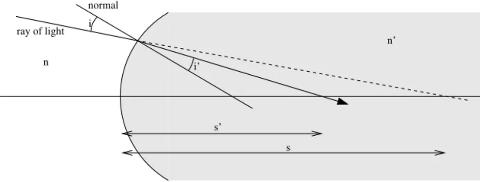
Figure 2.2: Refraction of light at a spherical interface between a medium of refractive index n (left) and a medium of larger refractive index n
"(right).
n
u u’
s s’
n’
R
h’
h