New Luminescent Europium Complexes as Indicators and in Sensors for pH in Biosamples and Water Samples
Dissertation zur Erlangung des Doktorgrades der Naturwissenschaften (Dr. rer. nat.)
der Fakultät Chemie und Pharmazie der Universität Regensburg
Deutschland
vorgelegt von
Wafaa Waleed Nafea Al-Qaysi aus Iraq (Baghdad city)
im Jahr 2018
Die vorgelegte Dissertation entstand in der Zeit von November 2014 bis November 2018 am Institut für Analytische Chemie, Chemo‐ und Biosensorik der Universität Regensburg.
Die Arbeit wurde angeleitet von PD Dr. Axel Düerkop.
Promotionsgesuch eingereicht am:03.10.2018 Kolloquiumstermin:15.11.2018
Prüfungsausschuss
Vorsitzender: Prof. Dr. Oliver Tepner Erstgutachterin: PD. Dr. Axel Dürkop Zweitgutachter: Prof. Dr. Antje J. Bäumner Drittprüfer: Prof. Dr. Rainer Müller
“To raise new questions, new possibilities, to regard old problems from a new angle, requires creative imagination and marks real advance in science.”
Albert Einstein
Acknowledgements
All praises and thanks are to Allah, the Lord of all the worlds, the most Beneficent, the most Merciful for giving me the opportunity to start and successfully complete this work.
I am indebted to a number of individuals and organizations who made the completion of this work possible. First of all, I'd like to thank my supervisor PD Dr. Axel Düerkop a lot for providing me with this interesting topic, for his readiness at all times to help and his critical suggestions, good advices, scientific discussions, as well as for his tireless support, encouragement during this thesis, and guidance were invaluable to the logical conclusion of this work. Moreover, I thank Prof. Dr.
Joachim Wegener for continuous encouragement, for his valuable guidance and support.
Furthermore, I thank Dr. Judith Stolwijk for continuous encouragement and for reading my thesis.
And, I thank Prof. Dr. Antje J. Bäumner as a co-supervisor for providing me for the opportunity to work independently, develop my scientific background, valuable discussions and her continuous support and for her acceptance to take part in my defense in a short time.
I also thank my group members, especially, Dr. Nongnoot Wongkaew for continuous encouragement and for frequent help at any time, Arne Behrent, a Ph.D student, for helping me in all kinds of situations, especially in the flow cell measurments, and kind thanks to Marcel Simesk, who helped whenever I was in need for anything.
A great thank you to Frau Angelika Stoiber, who helped me and left me her key for spectrometer instrument.
Kind thanks to Barbara Goricnik, who helped me whenever I was in need for finding chemicals, or anything else.
Furthermore, I would like to thank all my colleagues at the Institute of Analytical Chemistry, Chemo- and Biosensors at the University of Regensburg, for the excellent atmosphere and their help.
Great thanks to acknowledge the financial support of German Academic Exchange Service (DAAD) and the Iraqi Ministry of Higher Education for giving me the opportunity to pursue my doctoral degree in Germany with grant no. 57076438 within the BaghDAAD program.
Finally, very special thank to my whole family and especially my father and my mother for their invaluable support and their love.
Dedication to the spirit of my father
Contents
1. Introduction and aim of work ... 1
1.1 Lanthanides ... 1
1.1.1 The lanthanide series ... 2
1.1.2 Photophysics of lanthanide ions ... 5
1.1.3 Coordination chemistry ... 11
1.1.4 Luminescence quenching ... 11
1.1.5 Quantum yields () ... 12
1.2 Optical wide-range pH sensors ... 12
1.2.1 Theoretical Definition of pH that Uses the Hydrogen Ion Activity ... 13
1.2.2 The Experimental Definition ... 13
1.2.3 The glass electrode for wide range pH sensing ... 14
1.3 Optical sensors for wide range pH sensing... 19
1.3.1 Absorbance and reflectance-based pH sensors ... 22
1.3.2 Luminescence-based pH sensors ... 30
1.4 pH sensors in real samples ... 41
1.5 Response time & lifetime ... 43
1.6 Precision of pH measurements ... 44
1.7 Repeatability& reproducibility of pH measurements ... 44
1.8 Effect of ionic strength ... 45
1.9 Aim of work ... 46
1.10 References... 47
2. A luminescent europium complex for wide-range pH sensors and ... 59
sensor microtiterplates ... 59
2.1 Introduction... 59
2.2 Results and discussion ... 62
2.2.1 Tested Eu/Tb - complexes with diferrent ligands as a potential wide- ... 62
range pH indicator. ... 62
2.2.2 Choice of ligands and conceptual remarks ... 67
2.2.3 Absorption spectra ... 68
2.2.4 Excitation spectra ... 71
2.2.5 Emission spectra ... 73
2.2.6 Excitation spectra of pH-sensor membrane ... 78
2.2.7 Emission spectra of pH-sensor membrane ... 80
2.2.8 Response time and reversibility of pH-sensor membrane ... 81
2.2.9 pH sensor microtiterplate ... 83
2.3 Conclusion ... 85
2.4 Experimental section ... 85
2.5 References... 87
3. Sensor and sensor microtiterplate with expanded pH detection ... 91
range and their use in real samples ... 91
3.1 Introduction... 91
3.2 Results and discussion ... 94
3.2.1 Choice of ligands and conceptual remarks ... 94
3.2.2 Absorption spectra of the indicator ... 95
3.2.3 Excitation spectra of the indicator ... 97
3.2.4 Emission spectra of the indicator ... 98
3.2.5 Excitation spectra of pH-sensor membrane ... 100
3.2.6 Emission spectra of pH-sensor membrane ... 101
3.2.7 Response time and reversibility of pH-sensor membrane ... 102
3.2.8 pH sensor microtiterplate ... 104
3.2.9 Application of the pH sensor microtiterplate to real samples ... 105
3.3 Conclusion ... 106
3.4 Materials and methods ... 107
3.5 References... 109
4. Abbreviations... 112
5. Summary ... 114
5.1 In English ... 114
5.2 Zusammenfassung auf Deutsch ... 117
5.3 ي برع لا ب هص لا خ لا ... 121
6. Curriculum Vitae ... 127
7. Eidesstattliche Erklarung ... 130
1
1. Introduction and aim of work 1.1 Lanthanides
The word lanthanide originates from the Greek word lanthaneien translating into “lying hidden” [1]. The lanthanides represent the chemical elements from lanthanum to lutetium. The 18th century was the era of lanthanides. In 1752, a Swedish mineralogist discovered a heavy mineral from a mine. In 1789, Klaproth discovered the element uranium in pitchblende and uranium was isolated as a metal in 1841, by Peligot. In 1794, a Finnish mineralogist in Sweden discovered a heavy mineral then isolated an oxide named “ytterbia” (from the village, Ytterby). Later this oxide was separated into several fractions “yttria”, “erbia”, and “terbia”, these were found to be complex mixtures. The isolation of lanthanum, yttrium, and scandium was not completed until 1908-1909 owing to the difficulties in separating them by fractional crystallization: C. James obtained “pure'' Tm(BrO3)3 by 15000 recrystallizations. These difficulties arose because lanthanides have very similar chemical properties, with their dominant valence state being plus three (3+), while showing only small differences in formation and solubility of complexexs. These small differences decrease in size with increasing atomic number. In 1913 it was conclusively shown that there exist only 14 elements betweenn La and Hf by X-ray spectroscopy. Untill World War II, the only major advance in separating lanthanide ions was made by Mc Coy, who purified considerable quantities of Eu by reducing Eu3+ to Eu2+, followed by precipitation as EuSO4. During the 1930s & 1940s the first spectroscopic studies on aqueous lanthanide solutions were carried out [2]. It was found that some organic ligands (such as salicylaldehyde or benzoylacetonate) when excited in the ultraviolet (UV) region, can photosensitize the luminescence of europium ions, where Eu does not absorb light. Eu is found only at about 0.1% in the earth's crust. In 1945, the first radioactive promethium Pm was prepared. In 1962, cells were first stained with Eu and in the 1970s, a Finnish company, Wallac Oy (currently part of Perkin Elmer), began the studies with lanthanides as luminescent reporters for
2 time resolved immunoassays [3]. The technology developed by Wallac Oy spurred a rapid increase in the number of studies and applications in the field.
1.1.1 The lanthanide series
The lanthanide series consist of 15 elements from lanthanum La3+ (atomic number 57) to lutetium Lu3+ (atomic number 71) where the 4f–shell is filled from 0 to 14 electrons. These are called f-block elements because of the gradual filling of the last electrons in f-orbitals of the antepenultimate shell. Lanthanides can be extended with the elements scandium (Z = 21) and yttrium (Z = 39), having similar chemical and physical properties. Lanthanides are sometimes called rare earth elements [4]. Despite their name, rare earths are not less abundant in nature than tin, silver, gold, or platinum. In 1906, Becquerel, the first time observed the unusually sharp absorption lines of rare earth compounds, when he measured the spectrum of the mineral xenotime (YPO4 with traces of Er, Ce and Th). Around 1930, the sharpness of these lines could not be understood till Bethe [6], Kramers [7], and Becquerel [8] suggested that the lines may be due to electronic transitions within the 4f configuration, referred to as f-f transitions. In 1937, Van Vleck [9], showed using a very highly and simple instructive model of f-f transitions and that they become partially allowed as electronic dipole transitions. When we progress from cerium to lutetium, the 4f orbilals are gradually filled. These f orbitals have low radial expansion, and they are shielded from the chemical environment by the filled, energetically lower 5s and 5p sub-shells. Although lower in energy, these sub-shells are spatially located outside the 4f orbitals, causing the 4f electrons to have very little interaction with the chemical environment, and leading to the difficult separation of the lanthanides [10],[2]. Freed et al.[11], found that the relative intensities of the absorption lines of Eu3+ were different in different solvents and Weissman [12] discovered that complexes of Eu3+
with certain ultraviolet absorbing ligands were highly luminescent when excited by ultraviolet light.
Since Eu3+ it self has only a few, very weak absorption bands, solutions of this ion are not very brightly photoluminescent. Obviously, certain organic ligands can serve to photosensitise the luminescence of lanthanide ions. It was also found that lanthanide ions quench the fluorescence of
3 organic ligands. At that time, the optical spectra of lanthanide ions and the electronic energy level structure where only qualitatively understood. In the 1960s, Dieke [13] gave the 4fn energy levels of all trivalent lanthanides in the IR, visible and the UV spectral region. At the beginning of the 1960s, systematic studies of luminescent lanthanide complexes and their photophysics took place and these studies were mainly related to the β-diketonate complexes of Eu and Tb. In 1962, during the theoretical work of Judd [14], and Ofelt [15], calculation of the intensities of the electric dipole transitions between energy levels of the lanthanide ions. Todays, the Judd-Ofelt theory is used to describe and find the electronic spectra of lanthanide ions present in glasses and crystals. All lanthanides, except lanthanum, are f-block elements (have valence electrons in f orbitals). In general, electronic configuration of lanthanide atoms is usually represented as [Xe] 4fn5d16s2, where [Xe] represents the electronic configuration of the noble gas xenon, and n represents the number of electrons from 0 to 14 (0 with La to 14 with Lu). Depending on the relative energy levels, there are two types of electronic configurations for the lanthanide atoms: [Xe] 4fn6s2 and [Xe] 4fn−15d16s2 (n = 1–14). Lanthanum, cerium, gadolinium, and lutetium belong to the latter type, while in terbium both types of electronic configurations similar can be used any one. Ln3+ (with Ln referring to any lanthanide) is the most common oxidation state of lanthanide ions in aqueous solvents. Most lanthanide ions are stable. The electronic configuration of all the trivalent lanthanide ions is [Xe]
4fn, represented by the two 6s electrons, and the lost 5d electron [16].
A summary of the electronic configurations of lanthanide atoms and trivalent lanthanide ions is presented in Table 1. Some lanthanides are found as Ln2+ ions, because the 4f shell of the divalent ion is half filled [17]. While the other of lanthanides are found as Ln4+ ions, such as Ce4+. The highest oxidation state of lanthanides is the tetravalent state [18].
. .
4
Table 1 The electronic configurations of rare earth elements [17]. The lanthanides (from La to Lu) have filled inner orbitals with 46 electrons. Scandium and yttrium have 18 electrons in the inner orbitals.
As a result, several lanthanide ions show sharp line like spectra of free atoms or ions. Each lanthanide ion shows characteristic absorption and emission spectra and it can emit in the near-UV, visible, near infrared (NIR) and infrared (IR) regions of the electromagnetic spectrum upon irradiation with ultraviolet radiation. For instance, Sm3+ emits orange light, Eu3+ red light, Tb3+
green light, and Tm3+ blue light. Nd3+, Er3+, and Yb3+ are well-known for their near-infrared luminescence, but other lanthanide ions (Pr3+, Sm3+, Dy3+, Ho3+, and Tm3+) also show transitions in the near-infrared region. Most of the emitting lanthanide ions are luminescent, characterized by high color purity and are very attractive for technical applications, while the La3+ and Lu3+ are not luminescent in equal degree, and thus not useful in any optical applications. The luminescence intensity of a lanthanide ion is dependent on the quantum yield ).
Figure 1, shows the energy level diagram of aqueous lanthanide ions, and explains the energy gaps, [19]. Judged by the energy gap, Eu3+, Tb3+, and Gd3+ ions have the strongest luminescence. Eu3+
5 and Tb3+ are often used in bioanalytical applications. In addition to that intense emission in the visible wavelength, these emission have a particularly long lifetime [20].
Figure 1 A diagram depicting the approximate energy levels for aqueous lanthanide ions [21].
Lanthanides with exceptional photoluminescent properties have been used in a broad range of applications in fields such as X-ray crystallography, magnetic resonance imaging (MRI), optics, nuclear magnetic resonance (NMR) spectroscopy, lighting, metallurgy, bio-organic chemistry, medical diagnostics, and imaging [22].
1.1.2 Photophysics of lanthanide ions 1.1.2.1 Electronic energy levels
The number of electronic levels formed by [Xe] 4fn and electronic level is 3003 in Eu3+
and Tb3+ [23]. Depending on the number of electrons in the 4f orbitals, there are many ways to distribute these electrons. Figure 2, describes the interactions leading to different energy levels such as in Eu3+. The electronic configuration first is divided into termes because of the repulsion between the electrons within the orbitals. This interaction is termed Coulombic interaction. The terms are then split into J-levels, because of spin-orbit coupling, which is relatively large (103 cm-1) because of the heavy lanthanide. These represent the free ion levels and are described by the term symbols S, L, and J with the formula 2S+1LJ, where 2S+1 represents the total spin multiplicity, L is the total orbital angular momentum, and J the total angular momentum of the f electrons. Because of the 4f
6 orbitals are shielded by the filled electrons in the 5s and 5p sub-shells, the transitions are sharp between these levels. When the lanthanide ion is in a coordinating environment, (such as an inorganic crystal or an organic ligand), the J-levels are split into sublevels because of the electric field of the matrix. This splitting is usually small (102 cm-1) depending on the spectral resolution of the spectrometer and in the main emission bands of the lanthanide ion [24].
Figure 2 Diagram representing the interactions leading to the splitting of the electronic energy levels of a Eu3+ ion. In the digram, energy increases when going up [2].
1.1.2.2 Radiative transitions
The absorption and emission light results from two main types of transitions: the parity- allowed magnetic dipole (MD) transitions and the parity-forbidden electric dipole (ED) transitions.
Most absorption and emission light of lanthanides in complexes involvs redistribution of electrons within the 4f sub-shell (intraconfigurational f–f transitions) therefore (ED) transitions. For example the emission bands of the Eu3+ 5D0 → 7F1 transition are allowed as MD transitions, while the emission bands of Tb3+ require both, ED and MD mechanisms because the intensity of ED transitions in lanthanide ions are depending on the ligand field [2]. Hypersensitive transition means
7 the relative intensities emissions are very sensitive to the detailed nature of the ligand environment.
In Eu3+, this is 5D0 → 7F1 and 5D0 →7F2. Both MD and the ED transitions of lanthanide ions are weak compared to the “fully allowed” transitions of organic chromophores which causes long lifetimes to milliseconds in lanthanide complexes which depend on the lanthanide and matrix [2].
Some transitions require both MD and ED. Further, Eu3+ firstly accepts energy through its 5D1 and
5D2 levels above the emittive 5D0 level [25]. Tb3+ directly accepts energy by the 5D4 emittive level and decay to several 7Fn-levels.
1.1.2.3 Non radiative decay
The excited states in the lanthanide ions do not decay by radiative processes only. If the excited state and the next lower state energy gap are relatively small, luminescence will be in strong competition with the non-radiative decay of the excited state and depend on the number of matrix vibrations. In glasses and crystals the electronic excitation energy can be dissipated by vibrations of the matrix, a process known as multiphonon relaxation [26]. It can occur through coupling of the lanthanide energy levels with the vibrational modes in the direct surrounding of the lanthanide ion.
The high energy O-H vibrations are very efficient quenchers for lanthanide luminescence.
Therefore water molecules are avoided from the first coordination sphere of the lanthanide complexes. A similar relaxation process is more pronounced when lanthanide complexes carry organic ligands. In organic media suitable high-energy vibrations are more common [27]. The efficacy of matrix vibration mediated nonradiative relaxation is inversely proportionall to the number of vibrations quanta (phonons) required to bridge the gap between a given energy level and the next-lower one (radiative emission will efficiently compete with the non-radiative relaxation processes) [22].
Lanthanide ions usually require indirect excitation, named the “antenna effect”, or “sensitization of the metal-centred luminescence” because most of the transitions of the Ln3+ ions are related to the redistribution of electrons within the 4f sub-shell (intra configurational f–f transitions). This is a direct excitation of the lanthanide ions only producing low levels of luminescence (the weak f–f
8 transitions have absorption cross sections in the order of 1 M–1 cm–1), [19],[22]-[25]. This means the ion needs to form a complex with a sensitizing structure, such as an organic ligand containing a light absorbing chromophore structure.
1.1.2.4 The antenna effect
The lanthanide ions (f-f transitions) have very weak absorption coefficients (), which makes direct photo-excitation of the lanthanide ions difficult. However, this can be overcome by using the large absorption cross section of the organic chromophores and the energy transfer from organic chromophores to lanthanide ions (see figure 3).
Figure 3 General architecture of luminescent lanthanide complexes.
Thus, in order to design highly luminescent Ln3+ complexes, Weissman [12], first noticed the sensitization process in which the energy transfer takes place from coordinated ligands to the central metal ion.
Luminescent lanthanide complexes consist of a lanthanide ion encapsulated in one or more ligands.
Figure 3 shows that the organic chromophore ligand contains a light-absorbing group. Such a group is generally referred to as the antenna chromophore, in analogy to the light harvesting centra in photosynthetic reaction centers. The photonic energy absorbed by this antenna can be transferred to the encapsulated lanthanide ion, thus circumventing the photoexcitation bottleneck posed by the small absorption cross-sections of the lanthanide ions.
9 The β-diketonate complexes are known to be very efficient sensitizers for the lanthanide ions [28],[29]. Organic ligands coordinated to lanthanide ions have a twofold beneficial effect, they not only increase the light absorption cross section by ‘‘antenna effects’’ but also protect metal ions from vibrational coupling [30].
1.1.2.5 Lanthanide ion sensitization
Lanthanide ion sensitization occurs, when the ligand coordinates with the lanthanide.
This process protects the ion from the quenching effects of the aqueous matrix. Lanthanide luminescence is quenched through nonradiative relaxation processes, especially O–H vibrations (vibrational quenching). Water should be removed from the inner and the outer coordination sphere of the lanthanide ion [31]. Because of the large energy gap the terbium is not exposed to the quenching by O–H vibrations compared with the other lanthanides [17]. Terbium complexes may possess an energy back-transfer route from the emittive 5D4 level to an energetically close-lying ligand triplet state, which causes quenching of the luminescence and enhanced sensitivity to environmental conditions [32]. An energy difference of approximately 2500–3500 cm–1 is required to prevent this kind of energy back-transfer [24].
1.1.2.6 Ligand and lanthanide ion excitation
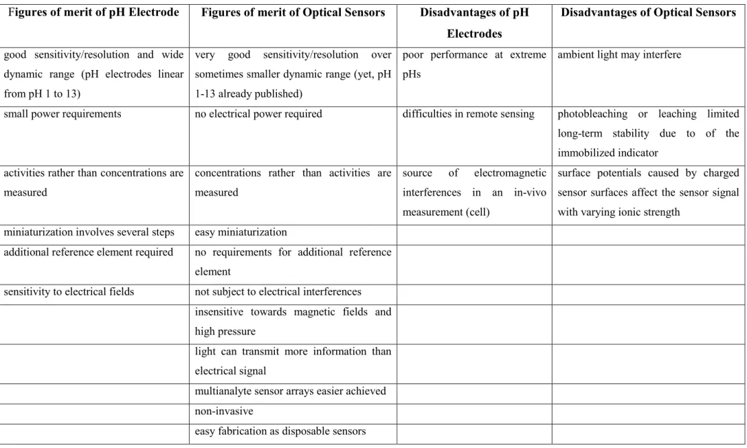
The mechanism of energy transfer from organic ligands to the lanthanide ion involves three steps: First, strong absorption from the ground singlet state (S0) to the excited singlet state (S1) of the ligand. Then excited singlet state (S1) decays non-radiatively to the triplet state (T1) via intersystem crossing, and finally the non-radiative energy transfer pathway from the T1 state of the ligand to excited states of the Ln3+ ion to emit light [1]. In some cases the direct energy transfer from the S1 singlet state to the excited Ln3+ levels is also observed.
A simplified scheme of these energy transfer processes, e.g., a Jablonski diagram, can be used to explain the processes related to lanthanide luminescence. This is illustrated in the figure 4 below.
10
Figure 4 Jablonski Energy Diagram of Absorbance Energy Transfer Emission (AETE) mechanism for a Ln3+
complex [33].
Most lanthanide complexes are excited in the near-UV range at wavelengths around 350 nm. The absorption of light by the lanthanide complex is a very fast process in the range of 10–15 s. It occurs from the ground state (low energy) to an excited singlet state (high energy). Internal conversion (IC) happens on the time scale of 10–12 s. From the original excited singlet energy state of the ligand, electrons vibrate or rotate down to excited vibration levels, or to the lowest excited electronic levels. Then, intersystem crossing (ISC) happens within a time scale of 10–13 s. The electrons relax from the excited singlet state (S1) to the excited triplet state (T1 lower energy), and from the excited triplet state (lower energy) through intramolecular energy transfer to the excited energy levels of the central ion. The singlet state is short lived, and the process is not efficient [20],[34].
There are two main mechanisms for the intramolecular energy transfer from excited triplet state (lower energy) to the central ion: the Dexter (electron exchange) mechanism and the Förster (dipole-dipole) mechanism [35]. The Dexter mechanism does require physical contact between the ligand and the central ion and includes electronic exchange between two components [36], while in the Förster mechanism does not require physical contact between the two components because the
11 triplet state transition dipole moment associates with the dipole moment of the 4f orbitals [5],[37].
In addition, there are other mechanisms, the metal to ligand charge-transfer (MLCT) from chromophores containing d-transition metal ions [38], and the ligand to metal charge-transfer (LMCT) when energy is transferred to the excited 4f-states of the lanthanide ion [39]. Lanthanide ions display f-f transitions and charge transfer transitions also display a third type of electronic transitions: the f–d transitions, meaning the promotion of a 4f electron into the 5d sub-shell [40].
1.1.3 Coordination chemistry
The study of coordination compounds or complexes has started in the nineteenth century with scientists such as Werner [41] who resolved the link between metal oxidation state and coordination number and developed the coordination chemistry.
The physical properties of a metal complex can be affected by the type of ligand. Ligands may be simple monoatomic structures, such as halides or large macromolecules with many coordination sites. The denticity is known as the number of sites on a molecule that are capable of coordinating.
Monodentate ligands are compounds with one coordination site, such as pyridine, while polydentate ligands are compounds with more than one coordination site.The physical properties of lanthanides are unlike those of the d-block metals. These properties are very similar and uniform across the row.
Lanthanides typically form eight or nine coordinate species, especially in aqueous solution where water molecules often coordinate to any sites around the ion. The complexes also exhibit rapid ligand exchange, except in the case of multidentate ligands, with water coordination residency times of around 10-9 s. Essentially, this means that the rate of exchange is determined by the diffusion of water molecules is the inner coordination sphere. This means that monodentate ligands are extremely unstable and highly kinetically inert lanthanide complexes can only be obtained through the incorporation of the ion into a macrocycle-based or rigid polydentate ligand.
1.1.4 Luminescence quenching
This non-radiative process occurs if a molecule in an excited state releases energy to a quencher and subsequently returns to the ground state [42]. Quenching can occur where the excited
12 states can be very short lived due to the efficient cascade of energy transfer from one component to another [43].
Quenching can also take place in an intermolecular manner through second-order rate kinetics. It causes decrease of the fluorescence intensity of a substance through either energy-transfer, complex formation, excited state, O-H vibrations, N-H and C-H vibrations [44].
1.1.5 Quantum yields ()
Quantum yields () is the ratio of the number of emitted photons (radiative) in relation to the number of photons absorbed as autlined equation (1) [24]. The quantum yield is also related to the the extent of the energy gap between the lowest excited energy level of the ion (called the
emittive energy level) and the highest sublevel of its ground state multiplet
= number of emitted photons / number of absorbed photons (1)
1.2 Optical wide-range pH sensors
The measurement of pH is still one of the most vital analytical methods in laboratory routine, research and measurements in the field for e.g. 1) pH is used as a quality parameter in clinical assessment of blood, body fluids, the freshness of food, drinking water and for treatment of industrial waste water. 2) pH is used to find the optimum reaction conditions in bioreactors, for precipitation of heavy metal ions from waste water and in industrial fermentation. Therefore, there are continuous attempts to find novel techniques for pH detection [45]. Nowadays, pH values are most often determined by using electrochemical sensors such as the pH glass electrode [46] or pH test paper strips or and optical pH-sensors.
Earlier reviews on optical pH sensors have been published by Wencel, et al. [80], Wolfbeis et al.
[81], Wolfbeis et al. [82], Lin et al. [83], Bilro et al. [84], Wolfbeis et al. [85], Seitz et al. [86], Janata et al. [87] and others. Recently, authors try to extend the measurement range of optical pH sensors. By this they want to overcome one major drawback of optical pH sensors using an equilibrium between a single protonated and unprotonated couple of indicator species. Due to the mass action law, this results in sensors which in most cases do not cover more than 3-4 pH units. As
13 glass electrodes (as the electrochemical competitors) offer a detection range that is typically larger than 12 pH units, there is a huge demand for optical wide-range sensors for pH because they offer some advantages with respect to miniaturization, remote sensing, imaging, sensing in-vivo, in the field or by non-educated staff that can hardly be reached by ion selective electrodes.
In this chapter the scientific literature on optical wide-range sensors for pH is shown that has appeared over the last two to three decades. They are ordered with respect to the detection methods and with respect to the sensor layouts. Initially a concluding overview over pH measurement by pH- electrodes is given mainly with the glass electrode. In the following sections their major properties are compared with those of the various optical detection methods. After some concluding remarks, an outlook is given on which sensing schemes seem to be promising for which field of application if detection ranges should be further extended.
1.2.1 Theoretical Definition of pH that Uses the Hydrogen Ion Activity
In 1920, Sørensen’s definition of pH, i.e. that pH = −log10[H+], was later revised, as further research demonstrated that pH is more related to hydrogen ion activity than hydrogen ion concentration. As a result, the new definition of pH is pH = -log aH+ where aH+ is the hydrogen ion activity. This is derived from Lowry’s recognition [47] of the activity of the hydronium ion instead of the hydrogen ion as the key to pH. The activity is an effective concentration of hydrogen ions, rather than the true concentration; It considers that other ions surrounding hydrogen ions will protect them and affect their ability to participate in chemical reactions. These other ions effectively change the hydrogen ion concentration in any process that involves H+.
1.2.2 The Experimental Definition
IUPAC has endorsed two pH scales based on comparison with a standard buffer of known pH using electrochemical measurements:
a) the British Standard Institution (BSI) scale has one fixed point, which is the reference buffer.
The pH of a potassium hydrogen phthalate solution with b = 0.05 mol/kg was set to be 4.000 + (T- 15)2·10-4, where T is the temperature. Any other standard solutions are derived by measurment with
14 a reference electrode and a hydrogen electrode. The signal includes a residual, non-eliminable diffusion potential. This scale is predominently used in Great Britain and Japan [48].
b) the National Bureau of Standards (NBS) scale uses several fixed points [49]. The fixed points are set by so-called primary pH standard solutions. The signal is determined with chains without electrochemical transport and is therefore free of a noneliminable diffusion potential. This scale is adopted by most national standards, e.g. Germany’s DIN 19266.
1.2.3 The glass electrode for wide range pH sensing
Nowadays, the pH glass electrode is the most common sensor for a wide-range pH measurement. In 1889, Nernst [50] worked in thermodynamics and invented the hydrogen electrode for [H+] for the first time. Cremer [51] studied the electric potential difference between a glass and an aqueous solution and plotted the electrical response of glass membranes to variable hydrogen ion concentrations in 1906. Then, Haber and Klemensiewicz [52] used the first glass electrode in 1909 based on bases Cremer’s detection principle and determined the electrochemical signals based on [H+]. In 1924 Schiller [53] found the magnitude of counter electric magnetic fields and applied potential difference to be same. Horovitz and Zimmermann [54] suggested that a certain proton concentration must be reached before the glass acts as electrode for H+. Few years later, MacInnes and Dole [55] found that the most suitable glass for a pH electrode had the composition 22 Na2O * 6 CaO * 72 SiO2 (Corning 015 glass). In 1937 Nicolsky [56] proposed the ion exchange equilibrium theory and worked on the thermodynamic description of the glass electrode. However, Haugaard [57] later concluded that thermodynamics alone cannot tell enough about the mechanism of the building of the glass boundary potential. In the 1960s, Durst [58] summarized the still accepted common knowledge that the response of the glass membrane occurs as a result of an ion exchange process which takes place in the gel layer of the glass membrane thereby inducing a phase boundary potential. This governs the pH response of the electrode but not a diffusion of hydrogen ions through entire glass membrane. Recent literature mostly supposed that ion exchange was the real physicochemical process responsible for the potential formation. In (1974) Baucke [59] developed
15 new techniques to increase sensitivity and resolution of glass electrodes. In (1980) Dole [60]
proposed steaming as a method of cleaning and offered a modified theory of the glass electrode by deducing an equation which fits accurately to the response in alkaline solution. Among the various types of pH measuring electrodes, the pH glass electrode nowadays is one of the most common types for highly accurate pH measurements or for studying of (de)protonation, coordination equilibria in aqueous solution (i.e. stoichiometry) [61]. The glass pH electrode is not as cheap as pH stripes but moderately expensive, and offers some advantages such as excellent electrode performances with respect to slope, sensitivity, selectivity to protons, limit of detection, reliability, distinguished response characteristics, long-term stability, fast response time, insensitivity vs redox systems and width of the dynamic pH range [62]. However, glass pH electrodes have some disadvantages such as bulky size and high resistance, they are prone to membrane pollution and instable in solutions containing fluoride and can show alkaline and acid errors. They may be a source of electromagnetic interferences in an in-vivo measurement (cell) and (due to mechanical frailty) unsuitable to be integrated into microfabricated electrochemical sensing systems for biological, industrial, environmental, and security applications [63], [64]. Therefore, several alternatives have been suggested to the glass membrane electrode such as ion-sensitive field effect transistors, metal oxide electrodes, and the quinhydrone electrode. The interference of fluoride could be compensated, recently [65] by employing a 5,17-bis(4-benzylpiperidine-1-yl)methyl- 25,26,27,28-tetrahydroxy-calix[4]arene as a ionophore in a polyvinylchloride (PVC) pH-sensing membrane. In fig. 5 two calibration curves of the measured potentials were plotted against the pH value from 1.9–12.9. The calix[4]arene electrode offers some advantages such as being inexpensive and easy to prepare. It has a wide linear working range and an almost Nerstian slope, a good selectivity and reproducibility for H+ ions, a broad pH working range and a quickresponse time of 6–7 s. The proposed calix[4]arene electrode has a wider linear working range and exhibits a better near-Nernstian slope of 58.77 1.1mVpH-1 which is more suitable than previous literature [66],
16 [67]. However, such electrodes might suffer from limited selectivity because they show reversible anion binding due to the ability of the protonated calix[4]arene by hydrogen bonds [68].
Figure 5 Calibration graphs of the proposed pH sensing membrane electrode plotted by the data obtained from pH ion meter and(b) potential graph [65].
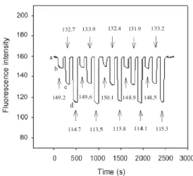
Compared with other electrodes [69], the response times are comparable or shorter and the electrode gives a fast response, and has a long life time at least 12 months.
Figure 6 Dynamic response of the proposed electrode for step changes in pH (1.9–12.22) [65].
Jović et al. [70] fabricated, characterized and applied sensitive pH sensors based on a nano- assembly of iridium oxide (IrO2) nanoparticles and polydiallyldimethylammonium (PDDA) polymer layers obtained via Layer-by-Layer Inkjet Printing (LbL IJP) methodology. LbL assemblies were composed of positively charged PDDA and negatively charged IrO2 citrate-
17 stabilized nanoparticles in various pH (2.9–10.37). This method is suitable for the production of thin nanofilm pH sensitive bilayers which are inexpensive, flexible, offer a fast response time, excellent reproducibility and near-Nernstian sensitivity. Fig.7 shows data of the pH-sensing properties and the reproducibility study. The pH electrode showed a linear response in the examined pH range. Compared with earlier literature [71] on oxidized Ir electrodes, the pH-sensing properties of IrO2 films are dependent of the structure, composition and oxidation state, which are impacted by the fabrication method. The response was rapid and stability was reached after 2–3 s. The good reproducibility of the inkjet printing processes was assed via the potential – pH dependence of five different 5-bilayer electrodes of the same batch (vs. Ag/AgCl (3 M KCl) reference electrode) using acid-to-base and base-to-acid measurements. Compared with the earlier electrodes of this type [72]
the LbL IJP electrode shows excellent reproducibility and a top-class reversibility of the response.
Figure 7 Acid-to-base and base-to-acid pH measurements of the different 5-bilayer IJP electrodes from the same printed batch. Inset plots represent the average potential –pH dependence for a)acid to base and b) base to acid direction.(the error bars represent the standard deviation of five different electrodes; bars are similer than the data symbols employed) [70].
Electrode-based pH sensing still has several drawbacks. Electrodes are prone to membrane pollution and a source of interference in in-vivo cell measurements and cannot be minimized or changed to sub-µm size. This is a disadvantage when pH detection in very small volumes such as cells or cell organelles is required. Additionally, a reference electrode is required. Furthermore, pH electrodes show weak performance in both extremes of the pH scale, especially in the highly
18 alkaline region because of the alkaline error. Despite the high selectivity of glass electrodes to hydrogen ions, particularly Li+, Na+ and K+ can induce errors in pH measurements in concentrated solutions at pH > 9. At high pH, the hydrogen ion activity (and hence, concentration) is low. Then, protons in the outer gel layer of the glass membrane may be exchanged by the cations. As a result, erroneous potentials across the glass membrane and thus erroneous pH will be acquired. This leads to lower pH value measured than is actually present in the sample. pH electrodes with special glass membranes for use in high alkaline media are therefore offered [73].
In highly acidic solutions the acid error may occur. At very low pH values (typically < – 0,5) acid molecules are absorbed by the gel layer leading to a decrease in the hydrogen ion (H+) activity in the gel layer. The pH measurement, therefore, shows a higher pH value than actually present in solution. Due to its occurrence at only very low pH this error is rarely relevant in practical applications and further reduced in lithium silicate glasses [74].
Additionally the fluoride and the phosphate errors have been described more recently [75].
They may occur, if La2O3-containing membrane glasses are employed in presence of on the said anions. These errors arise due to the formation of lowly soluble LaF3 and LaPO4 at medium to high pH values at the membrane surface after about 1 h induction time. Potential deviations until -35 mV are possible and remain until long-term measurements at pHs below 5 are performed.
The drift of the diffusion potential is a common source of error, if a Ag/AgCl reference electrode is used in KCl. Dilution of KCl in the porous plug induces a precipitation of AgCl or Ag(s) (if the sample contains reduction agents) inside the porous plug. Both precipitation reactions lead to a drift of the diffusion potential and hence, a drift of the pH detected. This can be compensated by recalibration about every second hour. Finally, different temperatures of calibration and sample measurements may induce erroneous pH reads, as well as a swelling time of less than several hours of a dry electrode in water, before calibration is performed. One should be patient until taking pH in solutions of low ionic strength because the equilibrium at the electrode might require several minutes to form [76].
19 All these interferences or sources of potential errors show that there is an increasing need for alternative ways to determine pH. One such alternative is the optical pH sensor (optode). pH optodes are nowadays widely used for pH-measurement and can be based on the change of a wide variety of properties of (mostly visible) light such as absorbance, fluorescence intensity or lifetime, energy transfer, reflectance and refractive index.
1.3 Optical sensors for wide range pH sensing
Optical and electrochemical sensors can be regarded as the two groups of sensors with the highest importance. In the earlier years of optical chemical sensors, optical pH sensors represented a group of chemical sensors that are complementary to glass electrodes. This is outlined in the following table where can be seen that many desired properties that are typical for optical sensors are difficult to be achieved with electrochemical sensors (i.e. a glass electrode) and vice versa.
Moreover, some merits are given that may induce an unwanted problems when using an optical or electrochemical sensor. The reader may decide on the usefulness of those for his proprietary use depending on his individual requirements.
20
Table 2 Comparison of the properties between optical sensors and electrochemical sensors (i.e. a glass electrode).
Figures of merit of pH Electrode Figures of merit of Optical Sensors Disadvantages of pH Electrodes
Disadvantages of Optical Sensors
good sensitivity/resolution and wide dynamic range (pH electrodes linear from pH 1 to 13)
very good sensitivity/resolution over sometimes smaller dynamic range (yet, pH 1-13 already published)
poor performance at extreme pHs
ambient light may interfere
small power requirements no electrical power required difficulties in remote sensing photobleaching or leaching limited long-term stability due to of the immobilized indicator
activities rather than concentrations are measured
concentrations rather than activities are measured
source of electromagnetic interferences in an in-vivo measurement (cell)
surface potentials caused by charged sensor surfaces affect the sensor signal with varying ionic strength
miniaturization involves several steps easy miniaturization
additional reference element required no requirements for additional reference element
sensitivity to electrical fields not subject to electrical interferences insensitive towards magnetic fields and high pressure
light can transmit more information than electrical signal
multianalyte sensor arrays easier achieved non-invasive
easy fabrication as disposable sensors
21 The lack of the necessity of a reference electrode and the electrical safety are among the main reasons for an increasing need for alternative devices for pH measurements such as optical pH sensors (so called pH opt(r)odes). If highly charged indicators are used, even small changes in the IS can compromise sensor performance [77]. Therefore, such sensors should be used at constant IS only. Interferences of certain organic matter (in real samples) may limit the capabilities of both, electrodes and optical sensors because blocking of the glass membrane of electrode may occur or additional scatter that can compromise an optical readout. Optodes are considered the most long- standing and the best techniques for pH measurement and are further used in chemical and biological environments in solution and the gas phase, for monitoring of biochemical reactions and for physical applications such as measuring pressure, temperature, electric current and magnetic field [78]. pH optodes are based on changes of optical properties such as absorbance, fluorescence, luminescence, chemiluminescence, energy transfer or reflectance by measuring the intensity of light in various regions of the spectrum (UV, Visible, NIR, IR). Moreover, related properties such as light scattering, luminescence lifetime, refractive index, diffraction and polarization may vary upon changes of pH [79], [80]. pH optodes are more beneficial due to their flexibility, small size, low cost, fast response and light weight. Due to their electrical safety they may enable work in presence of flammable and explosive compounds and are suitable for continuous use in-vivo (e.g. in the blood stream) [81]. Moreover these sensors can be used in hazardous media without compromising their accuracy and have the ability to provide multiplexed or distributed sensing [80], [82], because of their small dimensions (down to µm size). They are suitable for remote sensing (even over distances of kilometres) and disposable use, which is typical for in-situ applications [83], [84], [85].
Unlike electrical sensors, pH optodes can be used for in-vivo measurements because of their immunity to electromagnetic interferences. Besides, optodes can monitor a broad range of parameters including pressure, temperature, and vibration [85]. This lead to the use of optical sensors in various fields such as chemical, biological, medical and telecommunication industries and in engineering research. Also pH optodes exhibit disadvantages such as leaching or
22 photobleaching of the optical probe due to limited long-term stability. Sometimes a poor selectivity and a limited dynamic range [86] is found. The response of pH optodes is a function of the concentrations of the acidic and basic forms of the indicator [87], which follows the mass action law (and associated with it, the Henderson-Hasselbalch equation) but not the activity of the hydrogen ion. Most optical pH-sensors consist of a pH-sensitive dye (i.e. a pH-indicator) immobilized in a polymer matrix which has to provide suitable mechanical and adhesive properties to prevent the indicator from leaching. Moreover, the polymer should be polar enough to permit a rapid access of the protons from the bulk solution into the membrane, so to provide a quick optical response of the sensor.
1.3.1 Absorbance and reflectance-based pH sensors
Most optical and fiber-optical pH sensors transduce reversible changes of the structure of the indicator that are induced by pH into changes of spectroscopic phenomena such as absorbance [88], and reflectance [89]. Absorbance or reflectance methods benefit from the fact that instrumentation is inexpensive and simple to use. Unlike luminescence intensities, absorbances measured by photometry do not vary from instrument to instrument because the ratio of transmitted to incident light is always detected. Furthermore, the change of absorbance and reflectance acquired by the instrument correlates to the color changes seen visually by the eye. This favors the use of such kind of sensors also by non-trained lab staff. On the other hand, both methods are not very sensitive and therefore require the use high concentrations of the pH indicator.
One of the first absorbance-based fiber-optical pH sensors for the physiological pH range was developed by Peterson et al. [90] in 1980. It was based on microspheres of polyacrylamide containing phenol red and smaller polystyrene microspheres (for light scattering) and responded in a pH range of 7.0 - 7.4 with almost 0.01 pH unit resolution. Microspheres have the merit that they can adsorb indicators on their huge surface or permit chemical bonding of pH indicators on the surface (and eventually inside the micropsphere) to reduce leaching of the indicator. Further, the indicator may be embedded inside the polymer of the microsphere. All those methods lead to a
23 higher concentration of the indicator in the sensor membrane which is beneficial for enhancing the resolution in photometry. A sensor using cellulose acetate gave a wider detection range [91]. In 1984, Kirkbright et al. [92] designed a fiber-optical probe based on bromothymol blue to demonstrate the use of colorimetric indicators in sensors with a working range from pH 7-11.
Edmonds et al. [93] used XAD-2 (styrene-divinylbenzene ion-exchanger copolymer) porous microspheres to absorb bromothymol blue as the indicator to optically probe pHs from 4-8 with a response time of 5 min. The suitability of four acid-base indicators immobilized on the same Amberlite XAD-2 resin for fibre-optic pH sensors was evaluated and an up to 3 pH units reflectance response was found [94]. Zemin et al. [78] compared the covalent immobilization of combinations of phenol red phenol blue and bromothymol blue on polyacrylamide microspheres embedded in a polytetrafluorethylene film. They fabricated a wide-range optical pH sensor that responded from pH 7- 10 within 2 min.
The use of only one indicator inside a sensor membrane usually leads to a restricted measurement range due to the ratio of protonated and deprontonated form of the indicator being dependent from the mass action law [95]. An example where thesingle pH indicators congo red (pKa 3.7) or neutral red (pKa 7.2) [96] were immobilized in a cellulose acetate membrane is a good example. The linear range of the sensor with congo red is pH 4.2–6.3 and the sensor with neutral red responds linearly from pH 4.1–9.0. Response time is about 20 s, the reversibility of the sensor is good and a 60 days long-term stability was found. Very similar optodes were published recently [97], [98]. A much wider range of pH response was found by bonding of a 1:1 mixture of neutral red and thionin (with different pKas) to an epoxy activated agarose film coated glass slide (ACGS).
This yielded a sensor capable to monitor a pH range of 0.5–12, with two different slopes of the calibration plot. A fast response occurred within 1–2 min and the long term stability was at least 3 months with no leaching. The ionic strength of a sample up to 0.5 molL−1 did not significantly alter the sensor response. The reproducibly from 6 replicated pH measurements was better than 0.20%
R.S.D. [99]. An autonomous and fully automated system for determination of pH within a
24 microfluidic chip coupled with an LED and a photodiode was constructed and validated for the pH range 4–9. The combination of phenol red, chlorophenol red and bromphenol blue gave an indicator mixture that is stable for > 8 months. The accuracy was good (RSD ≤2.82%) and the pH found in blind samples compared to the ones obtained by an accreted laboratory (≤5.96 % relative error) [100]. Hampshire et al. [101] developed optic a fiber sensor to detect the pH in the gastric tract of a dog in a range of 0.5- 7. The sensor comprises two absorbance indicators with three pKa values immobilized on polyacrylamide microspheres. Those were deposited on a plastic optical fibre. A precision better than 0.1 pH unit and an up to 3.5 min response time is found with a two wavelength measurment. The sensor is long-term stable with 0.2 pH unit drift over a 24 h and an interference of coloured or other substances or ionic strength in gastric juice samples was not found. Instead of using two or more pH indicators in one and the same sensor foil, the use of a dye with more than one deprotonable group on the same chromophore may be considered to construct a sensor. This principle is attractive for widening the detection range of a pH sensor because those dyes commonly have several pKas, and, associated with it, several colors. The pH-dependent equilibria between those are then used to measure pH over a wider range. A planar pH sensitive film was prepared by immobilizing purple cabbage pigment (which contains mainly an anthocyanin dye) as pH indicator in a sol–gel via dip-coating onto glass slides [102]. The sensor showed good reversibility between pH 2 and 7, a response time of 2 min and a linear range from pH 2 - 11. Another sensor using anthocyanines extracted from grapes was used in a novel green optical pH sensor [103]. Upon immobilization of the red grape extract on an optically transparent agarose biopolymer a wide range pH from 1–10 was covered. The response time was 3 min and the repeatability better than 0.3 % (RSD) and with no evidence of dye leakage.
The various pKas of bromopyrogallol red (BPR) indicator was used to construct sol-gel optodes in a silica matrix that responded reversibly from pH 3-9 within a minute, also in real samples [104]. This range is similarly wide as published in previous literature [105] for a sensor made with malachite green oxalate and bromocresol green indicators immobilized in a
![Figure 1 A diagram depicting the approximate energy levels for aqueous lanthanide ions [21]](https://thumb-eu.123doks.com/thumbv2/1library_info/3942320.1533537/12.892.57.871.234.479/figure-diagram-depicting-approximate-energy-levels-aqueous-lanthanide.webp)
![Figure 6 Dynamic response of the proposed electrode for step changes in pH (1.9–12.22) [65]](https://thumb-eu.123doks.com/thumbv2/1library_info/3942320.1533537/23.892.261.606.630.902/figure-dynamic-response-proposed-electrode-step-changes-ph.webp)
![Figure 11 Schematic of a no-core optical fiber with pH coating [121].](https://thumb-eu.123doks.com/thumbv2/1library_info/3942320.1533537/36.892.139.746.120.290/figure-schematic-core-optical-fiber-ph-coating.webp)
![Figure 12 Stability curve of no-core pH sensor for both acidic basic [122].](https://thumb-eu.123doks.com/thumbv2/1library_info/3942320.1533537/37.892.289.601.101.355/figure-stability-curve-core-ph-sensor-acidic-basic.webp)
![Figure 16 Fluorescence intensity versus pH values and the resulting linear relationship [141]](https://thumb-eu.123doks.com/thumbv2/1library_info/3942320.1533537/41.892.253.646.694.966/figure-fluorescence-intensity-versus-values-resulting-linear-relationship.webp)
![Figure 17 Optical response of the pH-sensitive agarose Petri dish [171].](https://thumb-eu.123doks.com/thumbv2/1library_info/3942320.1533537/49.892.303.584.648.972/figure-optical-response-ph-sensitive-agarose-petri-dish.webp)