characterization, thermal and mechanical properties
S. Palantöken ,1K. Bethke ,1V. Zivanovic ,1G. Kalinka ,2Janina Kneipp ,1Klaus Rademann 1
1Institut für Chemie, Brook-Taylor Srt. 2, Humboldt Universität zu Berlin, 12489, Berlin, Germany
2BAM, 5.3, Unter den Eichen 87, 12205, Berlin, Germany
Correspondence to: S. Palantöken (E-mail: sinem.palantoeken@chemie.hu-berlin.de)
ABSTRACT: Biopolymers are very efficient for significant applications ranging from tissue engineering, biological devices to water purification. There is a tremendous potential value of cellulose because of its being the most abundant biopolymer on earth, swellability, and functional groups to be modified. A novel, highly efficient route for the fabrication of mechanically stable and natural hydrogels is described in which cellulose and glycine are dissolved in an alkaline solution of NaOH and neutralized in an acidic solution. The dis- solving temperature and the glycine amount are essential parameters for the self-assembly of cellulose chains and for tuning the mor- phology and the aggregate structures of the resulting hydrogels. Glycine plays the role of a physical crosslinker based on the information obtained from FTIR and Raman spectra. Among the prepared set of hydrogels, CL5Gly30 hydrogels have the highest capacity to absorb water. The prepared CL5Gly30 gels can absorb up to seven times their dry weight due to its porous 3-D network structure. CL5Gly10 hydrogel exhibits 80% deformation under 21 N force executed. The method developed in this article can contribute to the application of heavy metal adsorption in aqueous solutions for water purification and waste management.© 2019 The Authors.Journal of Applied Polymer Sciencepublished by Wiley Periodicals, Inc. J. Appl. Polym. Sci.2020,137, 48380.
KEYWORDS:biopolymer; cellulose; hydrogel; natural; synthesis Received 5 April 2019; accepted 17 July 2019
DOI: 10.1002/app.48380
INTRODUCTION
Hydrogels are three-dimensional hydrophilic network structures provided via irradiation,1chemical or physical crosslinks in the macro- molecular chains.2,3Over the past decades, there has been a dramatic increase in the number of biopolymer hydrogel fabrications due to their unique properties such as swellability, nontoxicity, biodegradabil- ity, and biocompatibility.4–8As it is also addressed in Water, Waste and Energy Management 2018 and Green Chemistry and Sustainabil- ity Engineering 2018 conferences*; hydrogels are attracting wide- spread interest infields of personal hygiene products,9underwater devices,10water reservoirs for dry soils,11,12soft contact lenses,13water purification,14,15surface coatings,16controlled drug release systems,2,17 tissue engineering, wound healing dressings,18and cell immobiliza- tion19,20regarding their biocompatibility and biodegradability.21 Cellulose is the polymer of glucose, and it is found in copious amounts in plants and natural fibers22 [Figure 1(a)]. It is
environmentally friendly and leaves little traces of carbon footprint. It is classified as bacterial cellulose (BC) or plant cellu- lose (PC) according to its sources. The glucose units are held together by 1,4-β-glycosidic linkages. BC has more benefits com- pared to PC. It has an ultrafinefiber network structure and better mechanical properties. Additionally, BC is obtained purely, while PC is associated with lignin and pectin. Because of its lignin con- tent, the PC requires further purification steps.21 In this study, microcrystalline cellulose from S3 Handel und Dienstleistungen UG(CAS. 9004-34-4) is used.
Particular attention has been paid to develop cellulose-based devices for biomedical applications, biosensors,23 supercapacitors,24 and nanocomposite hydrogels.25It is important to emphasize that cellu- lose is a bio-durable material. Since animal and human tissues are not able to synthesizecellulaseenzymes, resorption of cellulose does
Additional Supporting Information may be found in the online version of this article.
© 2019 The Authors.Journal of Applied Polymer Sciencepublished by Wiley Periodicals, Inc.
This is an open access article under the terms of the Creative Commons Attribution License, which permits use, distribution and repro- duction in any medium, provided the original work is properly cited.
*Water, Waste and Energy Management 2018, 18–20th July 2018, Madrid, Spain, http://waterwaste18.com/. Green Chemistry and Sustainability Engineering 2018, 23–25th July 2018, Madrid, Spain, http://greenchemistry18.com/.
not occur.21This feature of cellulose has triggered the development offlexible cellulose compositions for the use of artificial nerves in 3D printed electronic structures.26
A high number of crosslinking agents and catalysts have been studied to produce cellulose derivative hydrogels. As crosslinkers in cellulose hydrogels mostly epichlorohydrin,27,28 aldehydes,29 urea deri- vatives,30carbodiimides31and carboxylic acids32,33are used.21 During the dissolution of cellulose in sodium hydroxide solutions at lower temperatures, the gelation process occurs owing to the cellulose–cellulose network formation associated with a micro- phase separation of urea [Figure 1(b)].34 However, the role of urea in cellulose dissolution is not understood very well. There are two ─NH2 groups joined by a carbonyl (C O) functional group in the molecular structure of urea.
Glycine is the simplest amino acid, which has a primary amine and a carboxylic acid group [Figure 1(c)]. Fabrication of cellulose hydrogels via crosslinking them with glycine has been a question of great interest.34As glycine is amphoteric, it would be a practi- cal candidate to work in acidic and basic solutions.
Yaoet al. have investigated crosslinking of cotton cellulose in the presence of serine, glycine, and dimethyloldihydroxyethyleneurea and the physical properties of the crosslinked fabrics.35Remadevi et al. described glycine-treated cottonfibers at different pH values and studied their tensile, physical, and microstructure
properties.36However, hydrogel preparation with crosslinking of microcrystalline cellulose by glycine has not been at the primary focus of any research groups to the best of our knowledge. The idea of self-assembled cellulose-glycine hydrogels has also not been covered by the literature.
In this work, our goal is preparing cellulose hydrogels with gly- cine in alkaline medium. The swelling behavior, bonding struc- ture, morphology, reusability, thermal and mechanical properties were systematically investigated at different glycine amounts. It was found that the hydrogel CL5Gly30 (Alkaline glycine solution amount is 30% [v/v] of the total volume) demonstrated a high swelling degree due to its highly porous structure. In addition, mechanical strength was much higher at CL5Gly10 (glycine amount is 10% [v/v]) than neat cellulose in 80% deformation. As seen from the results, CL5Gly30 seems to be a potential substrate for heavy metal ion adsorption in the case of an adsorptive agent being loaded in the hydrogels.
EXPERIMENTAL Materials
Cellulose powder was purchased from S3 chemicals and was used without further purification, and it was always kept in the oven at 55C to get rid of the humidity in the material. The molecular weight is 324.28 g mol−1and degree of polymerization is below 350. Glycine was purchased from Alfa Aesar, Kandel-Germany.
Figure 1.Molecular structure of cellulose (a), urea, (b) and glycine (c). [Colorfigure can be viewed at wileyonlinelibrary.com]
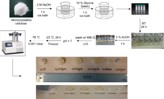
Figure 2.Experimental procedure for preparing cellulose and cellulose–glycine hydrogels. [Colorfigure can be viewed at wileyonlinelibrary.com]
Ultrapure water (Milli-Q) was used to prepare the aqueous solu- tions of 2 M NaOH and 5% acetic acid.
Synthesis of Pure Cellulose and Cellulose-Glycine Hydrogels An amount of 0.5 g of cellulose was dissolved in 10 mL of NaOH (2 M) and mixed in an ice bath (0–4C) for 1 h vigorously. CL5 denotes the cellulose amount that is dissolved in NaOH (0.5 g of cellulose). Additionally, an alkaline solution of glycine (10% w/v) is prepared by dissolving glycine in 2 M NaOH to use in the fur- ther steps. Different kinds of hydrogels were prepared. These CL5 hydrogels do not have glycine in it. CL5Gly10, CL5Gly20, CL5Gly30, CL5Gly40, and CL5Gly50 contain glycine with 10, 20, 30, 40, and 50 vol % of the total volume NaOH solution, respec- tively. For the glycine containing hydrogels, cellulose is dissolved in NaOH initially for 1 h. Successively, the calculated amount of glycine solution is added, and the mixture was stirred for an additional 1 h in the ice bath. After an additional hour of mixing, the viscous solution of cellulose is poured into molds and left overnight at room temperature. The following day, the gels were washed with 5% acetic acid (1 h) for neutralization. Additionally, the samples are washed several times until the pH of 7 is reached.
Subsequently, the hydrogels were frozen at −23C and then
lyophilized at −76C at 0.001 mbar (Alpha 1-4 LDPlus Freeze– Dry, Christ) (Figure 2).
Characterization Methods
The swelling behavior of the hydrogels was studied by gravimet- ric measurements. The freeze-dried hydrogels were weighed and immersed in Milli-Q water, and subsequently, time-dependent analysis of the swollen hydrogels was conducted. Samples are removed from the water and reweighed to study the time- dependent water uptake. All measurements took place at 25 C in a water bath. The percent swelling was calculated with the fol- lowing equation:
S%=ðmt–m0Þ=m0×100, ð1Þ where mt is the mass of the swollen gel at time tandm0is the mass of the dry gel.
The mechanical tests for the wet strength of the hydrogels were conducted with a modified Adamel Lhomargy DY.20B compres- sion test apparatus. As the transducer, a high sensitive piezo elec- tric force sensor Kistler 9311B was used and it was operated by a charge amplifier type Kistler 5011. The velocity of the traveling head was closed loop controlled by software developed in Bundesanstalt für Materialforschung und–prüfung (BAM). The software was also used for recording the time, force, and
Figure 3.Fourier transform infrared spectra of cellulose hydrogels. [Color figure can be viewed at wileyonlinelibrary.com]
Figure 4. Raman spectrum of cellulose and cellulose–glycine hydrogels.
Excitation wavelength, 785 nm; laser intensity, 1.4×10⁶ W cm−2; acquisi- tion time, 5 s; scale bars: 100 cps. [Color figure can be viewed at wileyonlinelibrary.com]
displacement during the test. The maximum speed of the travel- ing head was 1 mm s−1. However, the pressure tests with a veloc- ity of 0.2 mm s−1 were used. The force range was in 50 N in pressure mode and the force sensor was calibrated by using a ref- erence weight of 2 kg to match the force arising in the pressure tests.
Attenuated total reflection Fourier transform infrared spectra were collected in a Bruker VERTEX 70v FTIR spectrometer equipped with a DLa-TGS detector, using a diamond prism.
Raman spectra were excited at a laser wavelength of 785 nm with an excitation intensity of 1.4×10⁶ W cm−2 provided by a continuous-wave diode laser. The sample was placed on a CaF2
slide and the excitation light was focused on the specimens through a microscope objective. Raman spectra were acquired for durations of 1–5 s, depending on the sample. The Raman light was collected in backscattering geometry and detected by liquid nitrogen—cooled CCD (Horiba, Munich, Germany). The Raman spectra were frequency calibrated using a spectrum of toluene– acetonitrile (1:1) mixture.
Thermal gravimetric analysis (TGA) measurements were per- formed on a PerkinElmer Pyris 1 TGA.
RESULTS AND DISCUSSION
Fabrication of Cellulose–Glycine Hydrogels
FTIR spectra were obtained from the samples CL5, CL5Gly10, CL5Gly20, CL5Gly30, CL5Gly40, and CL5Gly50. All of these hydrogels show characteristic vibrational bands of cellulose bands, such as the O─H, CH, and C─O stretching vibrations at 3443, 2895, and 1053 cm−1, respectively, in accordance with liter- ature.37 (Figure 3) Glycine is believed to function as a physical crosslinker as the carbonyl stretching at 1734 cm−1does not have a distinct shift in the spectrum. Similarly, the absence of an amide or an ester band at around 1680 cm−1is an indication that the chemical crosslinking between cellulose chains and glycine does not occur.38(Figure 3).
In the samples CL5Gly60, CL5Gly70, CL5Gly80, CL5Gly90, and CL5Gly100, no gelation was observed. Here, Raman spectroscopy was used to fınd out about possible covalent bonding with glycine by observing the frequencies of characteristic cellulose vibrational bands.
The Raman spectra of cellulose and the cellulose–glycine hydrogels are shown in Figure 4 for the 300–1900 cm−1spectral range. Due to the overlapping bands assignments of glycine and cellulose, it is chal- lenging to observe a very clear broadening or shifting of the band Table I.Summary of Observed Raman Frequencies and Band Assignments
of Cellulose–Glycine Hydrogels, Based on Refs. 38–40
Raman
shift (cm−1) Tentative band assignment
350 CCC, COC, OCC, OCO skeletal bending, CCH, COH methane bending,
movement of CC, CO groups within the ring units 420
460 521 576
898 HCC, HCO bending, NH2twist
970 HCH bending
1094 COC stretching symmetric
1268 HCH (wagging), HCC, HOC, COH (rocking) bending, CH2twist
1371
1459 HCH scissoring
bending 1557
Figure 5.Scheme for physical crosslinking of cellulose hydrogels with glycine. [Colorfigure can be viewed at wileyonlinelibrary.com]
frequencies, since the changes are expected to be relatively small. As it can also be seen in Table I, all spectra display bands assigned to cel- lulose vibrations, in accordance with previously published data.39,40 The sharp COC symmetric stretching mode at 1095 cm−1and HCC, HOC, and COH bending vibrations at 1371 cm−1for cellulose are visible. In glycine containing hydrogels, the peak due to NH2twisting mode (898 cm−1) and CH2 twisting mode (1372 cm−1) shows a slight increase in intensity. The intensity change could be due to the increase in the amount of glycine in the cellulose hydrogels.38 The intensity increase of the skeletal bending and the movement of the carbon groups within the ring units between 350–576 cm−1 could be due to the interactions between glycine and cellulose. Signif- icantfindings of FTIR and Raman spectra are that the crosslinking between the cellulose and the glycine is very likely physical rather than chemical.
Crosslinking in polymer chemistry leads to a multidimensional extension of polymeric chains which results as a network struc- ture. It can be classified as ionic (physical) or covalent (chemical).
When a polymer is in liquid form, it can turn into a“solid” or
“gel” due to the chain crosslinking. Great attention is paid to crosslinked polymers as they are relatively resistant to heat, wear, and solvents in addition to being mechanically strong.41
Crosslinkers are generally known as toxic and physically crosslinked hydrogels are considered innovative because of being an alternate solu- tion for crosslinker toxicity. Physically crosslinked hydrogels can be formed by hydrogen bonds, crystallization, ionic interactions, protein interaction or from amphiphilic graft and block polymers.42In this case, it results from hydrogen bonding because the protonation of the carbox- ylic acid group in glycine takes place and pH-dependent swelling of the gels occurs. Ionic interactions are also important because cellulose is dis- solved in NaOH (2 M) in an ice bath for the extension of cellulose chains to form a multidimensional structure (Figure 5).42
Qualitative gravimetric analysis is also conducted in order to reveal the actual amount of glycine that incorporated in the hydrogel.
Ninhydrine test is conducted for this aspect. Ninhydrine test is a Figure 6.SEM images of cellulose hydrogels with different compositions of glycine (a) CL5 (×5000 magnification), (b) CL5Gly10 (×5000), (c) CL5Gly20 (×5000), (d) CL5Gly30 (×6500), (e) CL5Gly40 (×5000), (f) CL5Gly50 (×1500) hydrogels (Jeol, JSM–6060 with the imaging software of SEM Control User Interface V6.55 by JEOL). [Colorfigure can be viewed at wileyonlinelibrary.com]
sensitive test for primary amines to produce an intense blue color.
Only CL5Gly50 gave a slightly blue color. It can be considered that ninhydrine reacts with the deprotected amine groups of the free glycine remained in the hydrogel; however, one must be really care- ful to claim it as there is no distinct shift observed in FTIR and Raman spectra of cellulose-glycine hydrogels.
Morphology and Water Absorption Capacity of Cellulose–
Glycine Hydrogels
Scanning electron microscope (SEM) was used to analyze the surface morphology and microstructure of cellulose hydrogels. As can be
seen in Figures 6 and 7, the cellulose–glycine hydrogels have three- dimensional network structure where the pores are evenly distrib- uted. Micro-roughness of the hydrogels can be a benefit for the tissue engineering application as cellular adhesion, proliferation, and tissue formation are required for the scaffolds.43
The swelling curve of neat cellulose hydrogel and the hydrogels with different amounts of glycine are monitored conducting the test for three times for each sample, and the curves are drawn by taking the average values of the data for each point. The graph is shown in Figure 8 in accordance with the standard deviation for each curve.
Standard deviation for each curve can be seen in detail in Figures S1, Figure 7.Different magnification SEM images of CL5Gly30 hydrogels (a)×1000, (b)×2500, (c)×5000, (d)×10 000 (Jeol, JSM–6060 with the imaging soft- ware of SEM Control User Interface V6.55 by JEOL). [Colorfigure can be viewed at wileyonlinelibrary.com]
Figure 8. Swelling curves for cellulose and cellulose–glycine hydrogels.
[Colorfigure can be viewed at wileyonlinelibrary.com]
Figure 9.Polynomialfitting of compressive force—deformation curves for cellulose and cellulose–glycine hydrogels. [Color figure can be viewed at wileyonlinelibrary.com]
S2, S3, S4, S5, S6. Swelling increases with time up to a certain level and then it reaches an equilibrium state between swelling and deswelling. The equilibrated swollen state is reached in 1 h for CL5Gly10, CL5Gly20, CL5Gly30, and CL5Gly40. The water absorp- tion decreases for the hydrogels CL5 and CL5Gly50 due to the sepa- ration of the hydrogels into smaller pieces.
Thefirst quantities of water being absorbed by a gel might originate from the microvoids considering that capillary forces retain water. As CL5Gly30, hydrogel composition shows the optimum swelling behavior among cellulose hydrogels, it has been accepted the opti- mum 3-D network structure, which also can be observed in SEM images. Swelling capacity was improved from 600 to 700% (Figure 8).
Mechanical Properties of Cellulose–Glycine Hydrogels
There are various methods to study the mechanical properties of hydrogels. A dumbbell shape is used for most uniaxial tensile test- ing. However, for self-assembly material presented here, it is not possible to shape them before testing as they can get distorted.
Therefore, uniaxial compression is more suitable for cellulose– glycine hydrogels as they are examined in the swollen state. The mechanical properties of cellulose and cellulose–glycine hydrogels under uniaxial compression have been studied at ambient
temperature in the swollen state. The output of the mechanical tests was given as polynomialfitting of force (N) versus deforma- tion (%) curves of cellulose and cellulose hydrogels. A minimum number of five measurements were conducted for each composi- tion and average multiple curves for each composition were sketched and the polynomialfits were compared (Figure 9).
The force versus deformation curves differ at initial and higher rates of compression for the same sample as the sample geometry was not uniform at the beginning of the test. The geometry of the swollen network becomes more uniform at the higher rate of compression. Owing to that, the stiffness at higher compression rates is easier to compare than the beginning of the test (Figure 9).
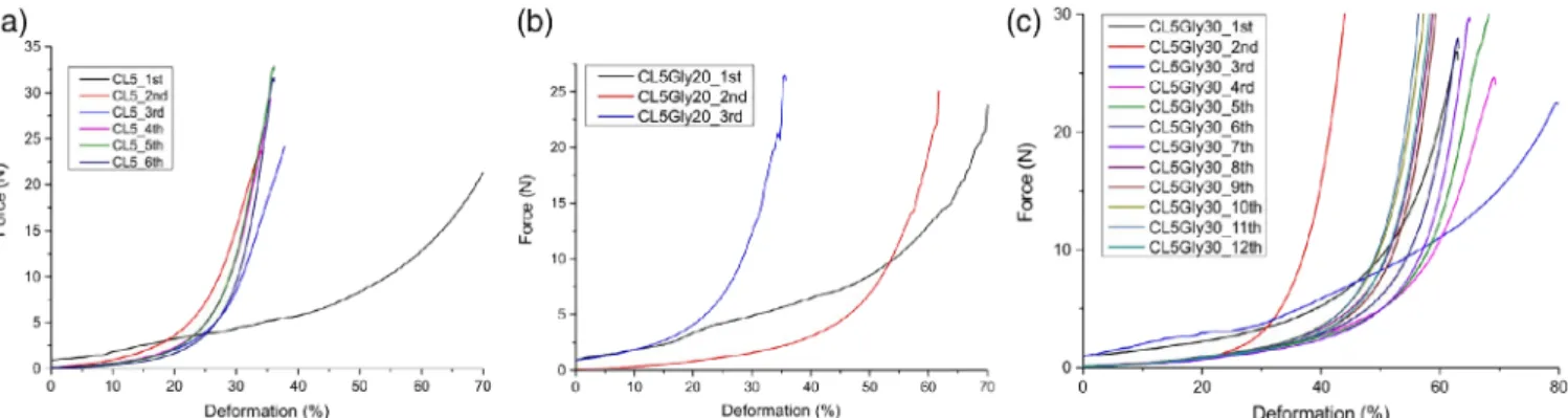
As expected, that the hydrogen bonds in the hydrogel structure act as crosslinks and the microcrystalline structure of cellulose shorten the elastic behavior of chains and the chain motion is restricted.44 Hydrogen bonds have a nonpermanent character and it leads to the spontaneous association of network junctions. Highly swollen CL5Gly10 and CL5Gly20 hydrogels exhibit rubbery networks and the correlation that higher force is needed for the same amount of deformation was previously interpreted. CL5Gly10 hydrogel exhibits 80% deformation under 21 N force executed. It is almost 1.5-fold of Figure 10.Compressive force—deformation curves for repetitive tests of (a) CL5, (b) CL5Gly209 and (c) CL5Gly30 hydrogels. [Colorfigure can be viewed at wileyonlinelibrary.com]
Figure 11. Swelling ratio for repetitive tests of cellulose and cellulose–
glycine hydrogels. [Colorfigure can be viewed at wileyonlinelibrary.com]
Figure 12.TGA thermograms of cellulose and cellulose–glycine hydrogels.
[Colorfigure can be viewed at wileyonlinelibrary.com]
the force, which is needed to deform the same percentage of the cel- lulose hydrogels without glycine. For the cellulose–glycine hydrogels with the lowest water content (CL5Gly40—450%, CL5Gly40—
200%), distortion increases drastically even if a small amount of force is exerted. It is probable that cellulose–glycine hydrogels behave as crosslinked when sufficiently swollen.
Reusability of Cellulose–Glycine Hydrogels
Particular attention is paid to the reusability of the hydrogels.
The force is exerted repetitively to observe the response of the hydrogels. It is noticed that an increased amount of force is required in the repeated cycles to result with the same amount of deformation [Figure 10(a–c)]. It can be explained with the microvoids disappearing with the force, which has already been exerted in the initial trial. When these hydrogels are tested
multiple times in a row, they are subject to water loss during the compression.45 Microcrystalline cellulose hydrogels are brittle and when the water is squeezed out, no more recovery can be observed in swelling. It is probable to conclude that the network structure in cellulose–glycine hydrogels is diminished and they are broken into fragments.
When there is no force exerted on the hydrogels and repetitive swelling experiments are conducted with the initial sample for each composition, a decrease in the swelling ratio is observed (Figure 11). However, a similar trend in the order of swelling ratio for the hydrogels is kept.
Thermal Properties of Cellulose–Glycine Hydrogels
Thermal gravimetry (TG) measurements were done in the tem- perature range from 30 to 800C with a heating rate of 20C min−1. The temperature range is kept wide enough in order to observe the possible changes in more detail. The TG experiments were performed once for each cellulose hydrogel composition under Ar using open pans. The sample masses var- ied between 3 and 14 mg. Additionally, for Figure S7, TG mea- surements were done from 250 to 750C with a rate of 5C min−1. The thermogram of CL5Gly20 and CL5Gly30 hydro- gels can be seen in a rough or more detailed curve.
As cellulose has six hydrophilic groups per unit molecule, which provide the possibility for water take up. There are three types of water in hydrophilic polymers: bound (nonfreezing), freezing- bound, free (not bound). The dry hydrogel samples were heated at a rate of 20C min−1. During the increase of temperature from 30 to 140C, there is a decrease in the weight of about 4%
(see Figure 12), which corresponds to the loss of water from the cellulose sample. There is a small amount of water, which is firmly bonded to cellulose molecules because dehydration process occurs at temperatures higher between 140 and 280C. Further loss of sample masses is monitored during the heating runs. The Figure 13.TGA derivative thermograms of cellulose and cellulose–glycine
hydrogels. [Colorfigure can be viewed at wileyonlinelibrary.com]
Figure 14.Photos of CL5 and CL5Gly10–50 hydrogels that are kept in pH 13. [Colorfigure can be viewed at wileyonlinelibrary.com]
Figure 15. Photos of CL5Gly10, CL5Gly20, and CL5Gly40 hydrogels that are kept in different solvents. [Color figure can be viewed at wileyonlinelibrary.com]
weight loss of cellulose mass observed between 278 and 420C reflects the thermal decomposition. There is a two-step process for some of the samples, and it can be seen easily in derivative thermograms (Figure 13). The second step of decomposition takes place between 420 and 600C. These curves show that the hydrogels are not durable above 280C, which is in good agree- ment with the previous studies on cellulose.46
Pink/Red Color of Cellulose–Glycine Hydrogels at Alkaline Condition
An orange–pink–red color of transition is observed when the hydrogels are kept in highly alkaline solutions. Samples that are shown in Figures 14, 15, and 16 are the examples of this observation.
The red color was observed in every composition of cellulose– glycine hydrogels except neat cellulose hydrogels. It is reasonable to suppose that those red pigments are the by-products of a D- Xylose-glycine reaction system. Shirahashiet al. studied a similar D-Xylose-glycine reaction system indicating red pigments as important Maillard reaction intermediates.47
The hydrogels in Figure 16 (CL5Gly30) were prepared in the same beaker and they have the same experimental parameters.
After the polymerization, first and second vials are treated the way explained in the experimental part and dry hydrogels are obtained. The third one was kept in water and has the pH of 13 due to the release of NaOH from the biopolymer. The fourth one in the row was kept in NaOH for 1 h and after extensive washing with water, by-products causing the red color were removed. It was washed until pH of 7 was obtained. Afterward, the vial was againfilled with NaOH (2 M) in order to obtain the possible color change to red, but it was not observed. The fifth
sample was kept at room temperature as a reference to see the changes and compare it with the others. Comparing with the ini- tial image of CL5Gly30 sample, it can be said that it turns into more yellow.
CONCLUSIONS
The synthesis of cellulose hydrogels physically crosslinked by gly- cine is conducted straightforwardly and is easily achieved. The results are highly reproducible on average but have a small spread. All properties of hydrogels mentioned in this article, in particular swelling, porosity, mechanical strength, thermody- namic durability, stability, and reusability, lead us to suggest that novel hydrogels can be applied successfully for heavy metal or dye adsorption in the area of water purification by loading special agents in them.
It is also advised that the novel cellulose–glycine hydrogels with excellent properties can be considered as a possible candidate for tissue engineering in soft electronics and cartilage tissue engineering.
ACKNOWLEDGMENTS
The authors would like to acknowledge Humboldt Universität zu Berlin for their support of this work. Funding from DFG GSC 1013 School of Analytical Sciences Adlershof (SALSA) for the authors S.P. and V.Z. is gratefully acknowledged and K.B. is most grateful for the scholarship from the International Max-Planck Research School at the Fritz Haber Institute. The authors also thank C. Erdmann and Prof. Pinna for SEM, B. Kobin and Prof.
Hecht for FTIR and TGA, F. Polster and Prof. Börner for the lyophilizer regarding the use of equipments. Portions of this work Figure 16.Photos of CL5Gly30 after different treatments. [Colorfigure can be viewed at wileyonlinelibrary.com]
(compression tests) were carried out with the help of G. Kalinka at BAM. The support from our colleague Mete Sungur Dalgic for proofreading is also appreciated.
REFERENCES
1. Chowdhury, M. N. K.; Alam, A. K. M. M.; Dafader, N. C.;
Haque, M. E.; Akhtar, F.; Ahmed, M. U.; Rashid, H.;
Begum, R.Biomed. Mater. Eng.2006,16, 223.
2. Peppas, N. A.; Bures, P.; Leobandung, W.; Ichikawa, H.
Eur. J. Pharm. Biopharm. 2000, 50(1), 27. https://doi.org/
10.1016/S0939-6411(00)00090-4.
3. Shen, X.; Shamshina, J. L.; Berton, P.; Rogers, R. D.Green Chem.2016,18, 53. https://doi.org/10.1039/c5gc02396c.
4. Peppas, B. N. A.; Hilt, J. Z.; Khademhosseini, A.; Langer, R.
Adv. Mater. 2006, 18, 1345. https://doi.org/10.1002/adma.
200501612.
5. Nakayama, B. A.; Kakugo, A.; Gong, J. P.; Osada, Y.;
Takai, M.; Erata, T. Adv. Funct. Mater. 2004, 14, 1124.
https://doi.org/10.1002/adfm.200305197.
6. Mckee, J. R.; Appel, E. A.; Seitsonen, J.; Kontturi, E.;
Scherman, O. A.Adv. Funct. Mater.2014,24, 2706. https://
doi.org/10.1002/adfm.201303699.
7. Luo, K.; Yang, Y.; Shao, Z. Adv. Funct. Mater. 2016, 26, 872. https://doi.org/10.1002/adfm.201503450.
8. Wang, C.; Fadeev, M.; Vázquez-gonzález, M.; Willner, I.
Adv. Funct. Mater. 2018, 28, 1. https://doi.org/10.1002/
adfm.201803111.
9. Pal, K.; Banthia, A. K.; Majumdar, D. K.Des. Monomers Polym.
2009,12(3), 197. https://doi.org/10.1163/156855509X436030.
10. Smith, M. J.; Flowers, T. H.; Cowling, M. J.; Duncan, H. J.
J. Environ. Monit. 2003, 5(2), 359. https://doi.org/10.1039/
b209822a.
11. Bakass, M.; Mokhlisse, A.; Lallemant, M. J. Appl. Polym.
Sci.2002,83(2), 234. https://doi.org/10.1002/app.2239.
12. Johnson, M. S. J. Sci. Food Agric. 1984, 35(11), 1196.
https://doi.org/10.1002/jsfa.2740351110.
13. Xiao, A.; Xiao, A.; Dhand, C.; Leung, C. M.; Beuerman, R. W.;
Ramakrishnaef, S.; Lakshminarayanan, R.J. Mater. Chem. B.
2018,6, 2171. https://doi.org/10.1039/c7tb03136j.
14. Wang, G.; He, Y.; Wang, H.; Zhang, L.; Yu, Q.; Peng, S.;
Wu, X.; Ren, T.; Zeng, Z.; Xue, Q. Green Chem. 2015, 17, 3093. https://doi.org/10.1039/c5gc00025d.
15. Palantöken, S.; Tekay, E.; S¸en, S.; Nugay, T.; Nugay, N.Polym Compos.2016,37(9), 2770. https://doi.org/10.1002/pc.23473.
16. Francois, P.; Vaudaux, P.; Nurdin, N.; Mathieu, J.;
Descouts, P.; Lew, P.Biomaterials.1996,17(7), 667.
17. Hamidi, M.; Azadi, A.; Ra, P. Adv. Drug Deliv. Rev.2008, 60, 1638. https://doi.org/10.1016/j.addr.2008.08.002.
18. Balakrishnan, B.; Jayakrishnan, A.; Kumar, S. S. P.;
Nandkumar, A. M.Trends Biomater. Artif. Organs.2012,26(3), 139. https://doi.org/10.1016/j.biomaterials.2005.04.012.
19. Jen, A. C.; Wake, M. C.; Mikos, A. G. Biotechnol. Bioeng.
1996, 50(4), 357. https://doi.org/10.1002/(SICI)1097-0290 (19960520)50:4<357::AID-BIT2>3.0.CO;2-K.
20. Yang, X.; Liu, G.; Peng, L.; Guo, J.; Tao, L.; Yuan, J. Adv.
Funct. Mater.2017,27(40), 1. https://doi.org/10.1002/adfm.
201703174.
21. Sannino, A.; Demitri, C.; Madaghiele, M.Materials.2009,2 (2), 353. https://doi.org/10.3390/ma2020353.
22. Bethke, K.; Palantöken, S.; Andrei, V.; Roß, M.;
Raghuwanshi, V. S.; Kettemann, F.; Greis, K.; Ingber, T. T. K.;
Stückrath, J. B.; Valiyaveettil, S.; Rademann, K. Adv. Funct.
Mater. 2018, 28, 1800409. https://doi.org/10.1002/adfm.
201800409.
23. Cunha, I.; Barras, R.; Grey, P.; Gaspar, D.; Fortunato, E.;
Martins, R. Adv. Funct. Mater. 2018, 27(16), 1601755.
https://doi.org/10.1002/adfm.201606755.
24. Pérez-madrigal, M. M.; Edo, M. G.; Alemán, C. Green Chem.2016,18, 5930. https://doi.org/10.1039/c6gc02086k.
25. Nascimento, D. M.; Nunes, Y. L.; Figueirêdo, M. C. B.; de Azeredo, H. M. C.; Aouada, F. A.; Feitosa, J. P. A.;
Rosa, M. F.; Dufresne, A. Green Chem. 2018, 20, 2428.
https://doi.org/10.1039/c8gc00205c.
26. Zhou, Y.; Wan, C.; Yang, Y.; Yang, H.; Wang, S.; Dai, Z.
Adv. Funct. Mater. 2019, 29, 1. https://doi.org/10.1002/
adfm.201806220.
27. Zhou, J.; Chang, C.; Zhang, R.; Zhang, L.Macromol. Biosci.
2007,7(6), 804. https://doi.org/10.1002/mabi.200700007.
28. Zhao, D.; Huang, J.; Zhong, Y.; Li, K.; Zhang, L.; Cai, J.
Adv. Funct. Mater.2016, 26, 6279. https://doi.org/10.1002/
adfm.201601645.
29. Syverud, K.; Kirsebom, H.; Hajizadeh, S.; Chinga- Carrasco, G. Nanoscale Res. Lett. 2011, 6(1), 626. https://
doi.org/10.1186/1556-276X-6-626.
30. Chen, J.; Yeh, J.; Chen, C.J. Appl. Polym. Sci. 2003, 90(6), 1662.
31. Sannino, A.; Pappadà, S.; Madaghiele, M.; Maffezzoli, A.;
Ambrosio, L.; Nicolais, L. Polymer. 2005, 46(25), 11206.
https://doi.org/10.1016/j.polymer.2005.10.048.
32. Hsiung, H.; Huang, H.; Wang, Y.; Wang, C.; Chen, J.;
Chen, C.J. Appl. Polym.2004,92(80), 3886.
33. Wang, C. C.; Chen, C. C.Appl. Catal. Gen.2005,293(1–2), 171. https://doi.org/10.1016/j.apcata.2005.07.007.
34. Egal, M.; Budtova, T.; Navard, P. Cellulose. 2008, 15(3), 361. https://doi.org/10.1007/s10570-007-9185-1.
35. Yao, W. H.; Chen, J. C.; Hu, M. S.; Teng, M. Y.;
Huang, P. H.; Lin, J. M.; Chen, C. C. J. Appl. Polym. Sci.
2005,97(2), 595. https://doi.org/10.1002/app.21282.
36. Remadevi, R.; Gordon, S.; Wang, X.; Rajkhowa, R. Text Res. J. 2017, 88, 1356. https://doi.org/10.1177/00405175 17700196.
37. Gaspar, D.; Fernandes, S. N.; De Oliveira, A. G.;
Fernandes, J. G.; Grey, P.; Pontes, R. V.; Pereira, L.;
Martins, R.; Godinho, M. H.; Fortunato, E.Nanotechnology.
2014, 25(9), 094008. https://doi.org/10.1088/0957-4484/25/
9/094008.
38. Kumar, S.; Rai, A. K.; Singh, V. B.; Rai, S. B.Spectrochim.
Acta, Part A: Mol. Biomol. Spectrosc. 2005, 61(11–12), 2741. https://doi.org/10.1016/j.saa.2004.09.029.
39. Schenzel, K.; Fischer, S. Cellulose. 2001, 8(1), 49. https://
doi.org/10.1023/A:1016616920539.
40. Wiley, J. H.; Atalla, R. H.Carbohydr. Res.1987, 226, 113.
41. Maitra, J.; Shukla, V. K. Am. J. Polym. Sci. 2014,4(2), 25.
https://doi.org/10.5923/j.ajps.20140402.01.
42. Akhtar, M. F.; Hanif, M.; Ranjha, N. M. Saudi Pharm J.
2016,24(5), 554. https://doi.org/10.1016/j.jsps.2015.03.022.
43. Kyle, S.; Jessop, Z. M.; Al-Sabaha, A.; Hawkins, K.;
Lewis, A.; Maffeis, T.; Charbonneaue, C.; Gazzec, A.;
Francis, L. W.; Iakovlev, M.; Nelson, K.; Eichhorn, S. J.;
Whitaker, I. S. Carbohydr. Polym. 2018, 198, 270. https://
doi.org/10.1016/j.carbpol.2018.06.091.
44. Tulonen, J.; Kolseth, F.Holzforschung.1987,41(4), 225.
45. Anseth, K. S.; Bowman, C. N.; Brannon-peppas, L.Bioma- terials.1996,17(17), 1647.
46. Szczesniak, L.; Rachocki, A.; Tritt-Goc, J. Cellulose. 2008, 15(3), 445. https://doi.org/10.1007/s10570-007-9192-2.
47. Shirahashi, Y.; Watanabe, H.; Hayase, F.Biosci., Biotechnol., and Biochem. 2009, 73(10), 2287. https://doi.org/10.1271/bbb.
90382.
![Figure 3. Fourier transform infrared spectra of cellulose hydrogels. [Color figure can be viewed at wileyonlinelibrary.com]](https://thumb-eu.123doks.com/thumbv2/1library_info/5655404.1694151/3.892.71.435.95.625/figure-fourier-transform-infrared-spectra-cellulose-hydrogels-wileyonlinelibrary.webp)
![Figure 5. Scheme for physical crosslinking of cellulose hydrogels with glycine. [Color figure can be viewed at wileyonlinelibrary.com]](https://thumb-eu.123doks.com/thumbv2/1library_info/5655404.1694151/4.892.69.438.131.417/figure-scheme-physical-crosslinking-cellulose-hydrogels-glycine-wileyonlinelibrary.webp)

![Figure 14. Photos of CL5 and CL5Gly10–50 hydrogels that are kept in pH 13. [Color figure can be viewed at wileyonlinelibrary.com]](https://thumb-eu.123doks.com/thumbv2/1library_info/5655404.1694151/8.892.70.434.92.361/figure-photos-gly-hydrogels-color-figure-viewed-wileyonlinelibrary.webp)
