Helmut Hörner, Samuel Rind, Sita Schönbauer
Praktikum Quantenphysik 141.A12 Helium-Neon Laser Experiments
Lab Report
Vienna University of Technology Institute of Atomic and Subatomic Physics
Contents
1 Introduction 3
2 Set-Up of the Laser 3
3 Fine Tuning by Maximizing Beam Intensity 5
4 Initial Laser Mode 6
5 Bifringent Crystal 6
6 Conclusions 7
7 Appendix 9
1 Introduction
The experiments described in this report were carried out by Samuel Rind, Sita Schön- bauer and Helmut Hörner on April 5, 2019 at the Institute of Atomic and Subatomic Physics of the Vienna University of Technology as part of the course "Praktikum Quan- tenphysik 141.A12". The experiments deal with setting up a He-Ne laser to continuous operation, and consequently with various methods of wavelength and mode selection.
2 Set-Up of the Laser
Figure 1: Alignment of right laser mirror, from [Beisteiner et al 2013, p.33]
When we got started with the set-up of the experiment, we already found the rail with mirror adjustment holder (7) in place, holding a VIS 700 high reflectivity mirror, as shown in figure 1. Hence, we immediately checked the alignment of this right laser mir- ror using the pilot laser (1), first without the laser tube in place, then with the laser tube in place between Iris (8) and mirror (7).
Only little additional adjustment of laser tube holder and mirror adjustment holder was required for a satisfactory alignment of the right laser mirror.
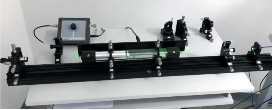
Figure 2: Preparations to fine-adjust the already adjusted right laser mirror
After that, iris (8) was moved to the other side, and the second laser mirror adjustment holder (2) was placed onto the rail immediately in front of the pilot laser, holding a high-reflectivity flat-surface mirror (VIS HR), and the back reflected beam was adjusted accordingly (see figure 3).
Figure 3: Alignment of left laser mirror, from [Beisteiner et al 2013, p.33]
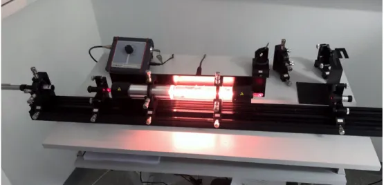
After inserting the tube (powered by a Leybold He-Ne Laser High Voltage Supply [HVS]), the laser immediately began to emit a continuous beam, as shown in figure 4.
Figure 4: Continous operation of the He-Ne laser after inserting the tube
3 Fine Tuning by Maximizing Beam Intensity
A Thor Labs photodetector [S120C], connected to a Thor Labs Compact Power and Energy Meter Console [PM100D] was manually inserted as shown in figure 5. Both mirrors were fine-adjusted as to maximize beam intensity. Eventually, a beam intensity of 5.12 µW could be accomplished.
4 Initial Laser Mode
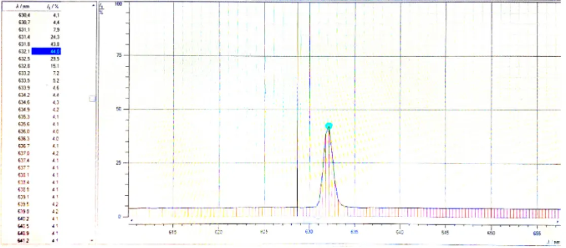
The spectrum (measured with [LD Spectrometer] 467 251 and analyzed using the Spec- traLab software package) shows a peak at 632.1 nm (see figure 6).
Figure 6: Peak at 632.1 nm (expected: 632.8 nm)
This does not exactly match the expected main line of 632.8 nm. Presumably, this offset of 0.7 nm is due to an inherit measurement offset in the [LD Spectrometer] used for spectral analysis.
5 Bifringent Crystal
Next, a bifringent tuner (BFT) (5) was inserted between tube and right laser mirror (see figure 7). With the the BFT set to the brewster’s aggle (57◦), the laser stopped working because of the beam shift caused by the BFT.
The required adjustments of the right mirror holder and the BFT-fine-tuning proved very difficult. Only after a complete re-calibration (involving a from-the-scratch adjust- ment using the pilot beam), we were able to get the laser running with the BFT set to the brewster’s aggle of 57◦.
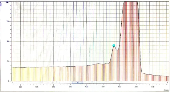
The spectral analysis no showed a secondary peak at 628.3 nm. We assume that this peak represents the line expected at 629.8 nm, and that the registered offset is caused by a systematic measurement problem of the used [LD Spectrometer].
Figure 8: Secondary peak at 628.3 nm with BFT inserted (expected: 629.8 nm)
Further efforts to readjust the system as to generate additional laser modes failed (we even tried to reverse-insert the BFT ).
6 Conclusions
The full width at half maximum of the intensity distribution is given by
The most likely speed of neon atomsνw can be calculated as
νw=
s2kBT
mN e (4)
WithmN e = 632.8 u,λ0 = 632.8 nm andL= 0.6 m, this leads to the number of expected modes:
∆ν
∆νDoppler = 5 (5)
from which in practice two, or maybe three modes can be expected to be actually mea- sured at wavelengths 632.8 nm, 640.1 nm, and 629.8 nm (with decreasing intensity).
In our experiment we were able to measured a clear peak at 632.8 nm, and (with the BFT in place), eventually a secondary peak at 628.3 nm. This is deviating from the expected wavelengths by 0.8 nm and 1.5 nm respectively. It is unclear which effect caused these deviations. Presumably, there is a problem in the [LD Spectrometer] used for spectral analysis.
7 Appendix
Equipment
[HVS] He-Ne Laser High Voltage Supply Leybold 473 303 [LD Spectrometer] Compact Spectrometer LD 467 251
[PM100D] Compact Power and Energy Meter Console Thor Labs PM 100D [S120C] Photodiode Power Sensor Thor Labs S120C, 400-1100nm
List of Tables List of Figures
1 Alignment of right laser mirror, from [Beisteiner et al 2013, p.33] . . . 3
2 Preparations to fine-adjust the already adjusted right laser mirror . . . . 4
3 Alignment of left laser mirror, from [Beisteiner et al 2013, p.33] . . . 4
4 Continous operation of the He-Ne laser after inserting the tube . . . 5
5 Measuring beam intensity for fine-adjustment of mirrors . . . 5
6 Peak at 632.1 nm (expected: 632.8 nm) . . . 6
7 Bifringent tuner inserted, from [Beisteiner et al 2013, p.38] . . . 6
8 Secondary peak at 628.3 nm with BFT inserted (expected: 629.8 nm) . . . 7
References
[Beisteiner et al 2013] M Beisteiner, C. Tscherne: Helium-Neon Laser. Setup and Ex- periments, 2013. Atominstitut Wien.
![Figure 1: Alignment of right laser mirror, from [Beisteiner et al 2013, p.33]](https://thumb-eu.123doks.com/thumbv2/1library_info/3901385.1524431/3.892.181.719.363.536/figure-alignment-right-laser-mirror-beisteiner-et-al.webp)