* Corresponding author E-mail: bjryu@kigam.re.kr
Gas hydrates in the Ulleung Basin, East Sea of Korea
Byong-Jae Ryu1, * and Michael Riedel 2
1 Korea Institute of Geoscience and Mineral Resources, Daejeon, Korea
2 GEOMAR Helmholtz-Centre for Ocean Research, Kiel, Germany
ABStrAct
To develop gas hydrates as a potential energy source, geophysical surveys and geological studies of gas hydrates in the Ulleung Basin, East Sea off the east coast of Korea have been carried out since 1997. Bottom-simulating reflector (BSR), ini- tially used indicator for the potential presence of gas hydrates was first identified on seismic data acquired in 1998. Based on the early results of preliminary R&D project, 12367 km of 2D multichannel reflection seismic lines, 38 piston cores, and multi-beam echo-sounder data were collected from 2000 to 2004. The cores showed high amounts of total organic carbon and high residual hydrocarbon gas levels. Gas composition and isotope ratios define it as of primarily biogenic origin. In addition to the BSRs that are widespread across the basin, numerous chimney structures were found in seismic data. These features indicate a high potential of the Ulleung Basin to host significant amounts of gas hydrate. Dedicated geophysical surveys, geological and experimental studies were carried out culminating in two deep drilling expedi- tions, completed in 2007 and 2010. Sediment coring (including pressure coring), and a comprehensive well log program complements the regional studies and were used for a resource assessment. Two targets for a future test-production are currently proposed: pore-filling gas hydrate in sand-dominated sediments and massive occur- rences of gas hydrate within chimney-like structures. An environmental impact study has been launched to evaluate any potential risks to production.
Article history:
Received 6 February 2017 Revised 14 September 2017 Accepted 21 October 2017 Keywords:
Gas hydrate, Ulleung Basin, Bot- tom simulating reflector, Chimney structure
Citation:
Ryu, B.-J. and M. Riedel, 2017: Gas hydrates in the Ulleung Basin, East Sea of Korea. Terr. Atmos. Ocean.
Sci., 28, 943-963, doi: 10.3319/
TAO.2017.10.21.01
1. INtrODUctION
Gas hydrate is a solid substance composed of water and natural gas, mainly methane (e.g., Makogon 1997;
Sloan 1998; Kvenvolden and Lorenson 2001), but it is sta- ble only under specific conditions, of low temperature and high pressure. Kvenvolden (1993) estimated the worldwide amount of methane in gas hydrates is to be equivalent to at least 104 gigatons of organic carbon. Moreover, gas hydrate is regarded as an environmentally energy source since the amount of CO2 release during methane combustion in gas hydrate is 70%, less than in currently used petroleum (Mat- sumoto et al. 1994). Thus, gas hydrate is regarded as a fu- ture energy resource (e.g., Boswell and Collett 2011) since it has represented a major reservoir of methane in the Earth.
Gas hydrate is easily dissociated to gas by small changes in temperature and/or pressure conditions. Methane escape into the atmosphere from gas hydrate reservoirs thus may
effect global and enhance global warming (see e.g., dis- cussion on the Clathrate gun hypothesis by Kennett et al.
2003 and other discussions such as MacDonald 1990; Haq 2000; Archer 2007). The dissociated methane and liberated fresh water may cause submarine landslides and subsidence (e.g., McIver 1982; Paull et al. 2000a; Maslin et al. 2010).
Therefore, studies on gas hydrate have attracted attention worldwide.
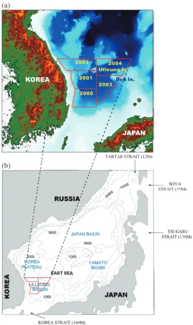
Here, we summarize evidences for the presence of gas hydrate in the Ulleung Basin, East Sea of Korea (Fig. 1) that reflect both regional and focused modes of gas hydrate accumulations.
A bottom-simulating reflector (BSR) is commonly used as a geophysical indicator of the presence of marine gas hydrates (e.g., described in the review by Spence et al.
2010), and is often used to provide an initial assessment of the potential gas hydrate distribution. BSRs occur at the in- terface between overlying gas hydrate-bearing sediments with higher velocity and underlying gas-bearing sediments
with lower velocity. BSRs are generally nearly parallel to the sea floor following an isotherm. BSR sub-bottom depths increase with increasing water depth, following the pres- sure-temperature phase stability of gas hydrate. They are often characterized by large reflection coefficients and re- flection polarity opposite to that of the seafloor reflection as shown by earlier studies (e.g., Shipley et al. 1979; Hyndman and Spence 1992; Paull et al. 1997).
Vertical to sub-vertical seismic blanking zones of re- duced reflectivity are one of the more recently recognized indicators of gas hydrate and are observed worldwide in as- sociation with upward focused fluid flow (e.g., Gorman et al. 2002; Riedel et al. 2002; Ryu et al. 2009; Petersen et al.
2010). Only a few of these structures have been studied in detail, but blanking zones are often associated with cold flu- id and gas vents characterized by extensive seafloor carbon-
ate formations and cold-vent chemosynthetic communities.
A number of hydrate samples were retrieved from blanking zones by piston coring and deep-drilling in the Ulleung Ba- sin (e.g., Park et al. 2008; Ryu et al. 2013).
However, where gas hydrate is not recovered (but dis- sociated during recovery), there are a number of indica- tors for the presence of in-situ gas hydrate. Features such as bedding-parallel cracks and sediment louse-like or soupy textures were well observed in cores of ODP Leg 146 (West- brook et al. 1994; Kastner et al. 1995), and are considered indicators for dissociation of in-situ gas hydrates. Cracks formed by gas expansion were also seen in Cascadia cores of ODP Leg 204 (e.g., Riedel et al. 2006a), and both cracks and soupy layers were observed in cores from the Ulleung Basin, (Ryu et al. 2004, 2009). Other indicators of in-situ gas hydrate that has dissociated upon recovery are cold core
Fig. 1. Physiographic map of the East Sea and the surrounding region. Box indicates study area expanded in (b).
(a)
(b)
temperatures immediately upon recovery (Long et al. 2003;
Tréhu et al. 2004; Riedel et al. 2006b; Su et al. 2006; Ryu et al. 2012, 2013), and reduced pore fluid chlorinities relative to a given regional background trend (Kastner et al. 1995; Paull et al. 2000b; Tomaru et al. 2006; Ryu et al. 2012, 2013).
Initial geophysical exploration and studies of the Ul- leung Basin were performed mostly to explore for conven- tional oil along the southern continental shelf since the late 1960s. Since the early 1990s, research surveys in the deep- water area of the East Sea were focused on the tectonic his- tory, sediment stratigraphy and paleoenvironment of the sea and were carried out by the Korea Institute of Geoscience and Mineral Resources (KIGAM) and the Korea Ocean Research and Development Institute (KORDI; currently Korea Insti- tute of Ocean Science and Technology: KIOST). Evidence for the presence of gas hydrate in the basin was first reported by Gardner et al. (1998) using side-scan sonar images, sedi- ment samples, and 3.5 kHz sub-bottom profiling data.
The occurrence of BSRs off Korea was first recognized by Jang et al. (1999) using multichannel seismic lines ac- quired using the R/V TAMHAE-II in the southwestern part of the Ulleung Basin. An additional, preliminary study of geophysical indicators of gas hydrates in the Ulleung Basin using multichannel seismic data was reported by Lee et al.
(2005). A regional geological and thermal interpretation was provided by Horozal et al. (2009) and Ryu et al. (2009).
As a part of the Korean National Gas Hydrate Pro- gram, the first Ulleung Basin Gas Hydrate Drilling Expedi- tion (UBGH1) was conducted in 2007 to delineate the gas hydrate potential in the basin (Park et al. 2008). Coring and downhole well logging were performed using the M/V Rem Etive. A total of five LWD/MWD boreholes, three core and in-situ testing boreholes in the vicinity of the correspond- ing LWD/MWD boreholes, and one WL/VSP survey were completed (Park et al. 2008). Although UBGH1 provided valuable information on the presence of gas hydrate in po- tentially significant amounts suitable for exploitation, gas hydrate-bearing sediments were confirmed at only a few sites. Sparse scientific information on the nature of gas hy- drate-bearing structures limited the ability to assess the re- gional gas hydrate resource potential. Thus, a second drill- ing expedition (UBGH2) was conducted in 2010 (Ryu et al. 2013) using the D/V Fugro Synergy. The objectives of UBGH2 were (1) to confirm the occurrence of gas hydrate- bearing sediments in the basin (at 13 sites), and (2) to obtain a suite of scientific information on the distribution of gas hydrate-bearing accumulations as needed to conduct a more rigorous gas hydrate resource assessment. Various types of gas hydrates were recovered during the 2nd drilling expedi- tion (Ryu et al. 2012, 2013) and results of the drilling expe- ditions are summarized below. Additionally, we report on results from piston cores analyses taken across the Basin in the years of 2000 - 2004 and new seismic data interpretation, augmenting the regional coverage of seismic data across the
basin. These data complement the vast amount of already existing geo-scientific knowledge of the gas hydrate occur- rences in the Ulleung Basin and provide a complementary view of the existing findings.
2. rEGIONAL SEttING OF tHE ULLEUNG BASIN The Ulleung Basin is located in the southwestern East Sea off the east coast of Korea (Fig. 1). The East Sea is a semi-closed marginal sea between the Eurasian continent in the West and the Japan Arc in the East. It is connected to the open ocean through shallow straits (12 - 140 m deep, Mori- yasu 1972). The East Sea is divided onto three deep oceanic sedimentary basins: Ulleung, Yamato, and Japan Basin. These basins are individually separated by submarine topographic highs such as the Korea Plateau, Yamato Ridge, and the Oki Bank. The western continental shelf of the basin is narrow (40 - 50 km) and flanked by steep slopes (2 - 4°), whereas the shelves on the south and east are broad and flanked by rather gentle slopes (< 2°). The basin floor gradually deepens to the north and northeast from 1000 - 2300 m. Several seamounts formed by volcanic activity in the northeastern part of the basinclose to Dok Island. The basin is connected northward to the Japan Basin through the Korea Gap previously known as Ulleung Interplain Gap, a long narrow interplain gap (Fig. 1) between Ulleung and Dok Islands.
During the Late Oligocene to Early Miocene period, the Ulleung Basin was formed through crustal extension as- sociated with a southward drift of the Japan Arc away from the Asian mainland (Chough and Barg 1987; Tamaki et al.
1992; Jolivet et al. 1995). At the end of the Middle Mio- cene (approximately at 12 Ma), the general tectonic regime within the basin changed from extensional to compressional (Yoon and Chough 1995; Chough et al. 2000). This led to the development of thrust faults and folds in the southern and western margin of the basin. Additionally, the sedimen- tary successions were exposed to compression associated with consolidation that may have been a driving force for the upward flow of gas-rich fluids and subsequent gas hy- drate formation (similar to processes postulated for an ac- cretionary prism by Hyndman and Davis 1992 or Hyndman et al. 1993). Since the end of the Late Miocene, the basin has progressively subsided until the present setting has been reached (Park et al. 2002).
The sediment succession in the Ulleung Basin has been divided into four seismic sequence units by Chough et al. (2000). The lowermost unit is of Late Oligocene - Early Miocene age and consists of volcanic flows and sills interbedded with sedimentary layers. This is overlain by a Middle Miocene unit consisting mostly of marine shales.
This second unit is relatively uniform in thickness across the central basin. However, to the northeast, it gradually transi- tions into a unit that is characterized by massive sandstone/
shale, volcaniclastic and turbidite sequences. This third unit
of Late Miocene to Early Pliocene age and consists again mostly of marine shale interbedded with thin sandstone and siltstone beds. Wiyjin this third unit, variation in grain size and associated permeability contrasts may provide signifi- cant controls on gas hydrate formation (either in form of coarse-grained host-sediments and/or fluid pathways). In the south-western region of the basin, this unit is in contrast characterized by occurrence of abundant slide or slump de- posits. The uppermost unit of Late Pliocene - Quaternary age is dominated by turbidite and hemi-pelagic deposits em- bedded within the otherwise dominant shale-sequences. The uppermost (and youngest) unit is of Late Pliocene-Quater- nary age. It is dominated by hemi-pelagic deposits interbed- ded with turbidites.
Based on this general geological setting and distribu- tion of sediments across the Ulleung Basin, a focus of the 2nd drilling expedition UBGH2 was to identify gas hydrate- bearing sand layers that could be economically developed (Boswell 2009). The regional sediment delivery system for sand was investigated and geologic models of sand occur- rence were defined using a petroleum system approach to gas hydrate exploration (as shown by Collett et al. 2009).
This also guided the site selection process for UBGH2.
Regional geothermal gradients were defined in the Ul- leung Basin from seismic data using the BSR as an isotherm (Ryu et al. 2009) and near-surface heat-probe deployments (Huh et al. 2005). In order to further assess the thickness of the gas hydrate stability zone (GHSZ) in the basin, tem- perature measurements were made during UBGH2. In-situ formation temperatures measured using the WISON EP system during the UBGH2 revealed a high geothermal gra- dient, ranging from 96 - 115°C km-1. The generally high geothermal gradients result in a shallow GHSZ, despite the large water depths exceeding 2000 m.
3. SUMMArY OF DrILLING EXPEDItIONS
The two drilling expeditions in 2007 and 2010 fol- lowed a similar strategy. Prior to drilling, a careful site se- lection process was conducted including discussions with an International Scientific Advisory Committee (ISAC) in which scientists from U.S. Department of Energy, US Geo- logical Survey, Geological Survey of Canada, Monterey Bay Aquarium Research Institute (MBARI), Birmingham University, Pukyong National University, Korea National Oil Corporation, and KORDI participated. The primary cri- teria used by the ISAC were (1) establishment of the extent of the gas hydrate stability zone (GHSZ), (2) evidence for gas sourcing and migration into the GHSZ, (3) evidence of gas hydrate presence within the GHSZ and, (4) evidence for the occurrence of a sand sedimentary facies within the GHSZ, suitable for potential production. A number of high priority sites were selected for drilling. Post-drilling verifi- cation of the main gas hydrate indicators chosen for drill-
site selection was performed by Kang et al. (2015).
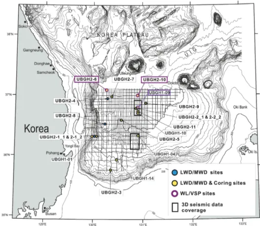
At each of these high priority sites (Fig. 2), first log- ging-while-drilling (LWD) was performed (5 sites for UBGH1 and 13 sites for UBGH2) to obtain first impres- sions on the possible occurrence of gas hydrates. The LWD data acquisition was performed together with measurement- while-drilling (MWD) tools for continuous safety monitor- ing, following protocols develop during previous gas hy- drate expeditions, such as IODP Expedition 311 (Riedel et al. 2006b) or the India National Gas Hydrate Program Expedition 01 (Collett et al. 2015). These data were used on board to select the best sites for coring and to develop a sampling and downhole-tools deployment program. Overall, the LWD data show various characteristics indicating pres- ence of gas hydrate-bearing sediments (Kim et al. 2011). A series of sites within seismic chimney are characterized by anomalous log data of high resistivity and velocity values, compared to the surrounding (non-hydrate-bearing) marine sediments. Moreover, log values of low density (less than 1.1 g cm-3) and low gamma-ray values much below the av- erage values indicate the presence of massive gas hydrates.
Gas hydrates at the seismic chimney sites occurred within steeply inclined fractures in overall mud dominated sedi- ments. These gas hydrate-filled fractures were also identi- fied on X-ray images of recovered pressure cores (Park et al. 2009). However, such preferred orientation of fractures does create anisotropic effects for bore-hole measurements as shown by Lee and Collett (2013a, b).
Gas hydrate saturations were estimated from the vari- ous LWD and wire-line log electrical resistivity and P-wave velocity data from both drilling expeditions (e.g., Kim et al.
2008a, b, 2013a, b; Riedel et al. 2012, 2013a, b; Lee and Collett 2013b). The various approaches and results do show similar overall concentration estimates for those sites out- side of seismic chimney structures (Ryu et al. 2013), but considerable difference were found for sites within seismic chimneys (Kim et al. 2013a). A different approach was taken by Tak et al. (2013) who estimated gas hydrate saturation at two Sites (UBGH2-6 and UBGH2-10) using wireline and vertical seismic profile (VSP) data. The VSP data allow the calculation of detailed interval velocities, but also yield high- resolution corridor-stack reflection images that can be com- pared to the 2D regional multichannel seismic data. Their analysis shows concentrations ranging from 30 - 90% of the pore space at Site UBGH2-6, and 35 - 57% at Site UBGH2- 10 in the corresponding gas hydrate-bearing intervals.
Gas hydrate-bearing sediments within the recovered conventional-wire cores were identified visually when pos- sible, but indirectly by cold infrared (IR) anomalies before core sectioning, and by low interstitial water salinities and chloride concentrations after pore-water extraction. Expan- sion cracks in the recovered conventional cores were also observed, which can indicate the presence of gas and/or gas hydrate in the core (e.g., Kvenvolden and Lorenson 2001;
Riedel et al. 2006b). Bahk et al. (2013a) defined the types of gas hydrates as “pore-filling” occurring sand layers, and
“fracture-filling” in veins and nodules or “disseminated”
type in mud without apparent lithologic controls. In addition,
“porefilling” hydrates in diatomaceous mud were also found where gas hydrate occupies sediment layers dominated by diatom frustules. The saturation of gas hydrate in the sandy sediment “pore-filling” type was shown to be directly related to sand content with the sedimentary section, with a nearly linear increase in gas hydrate saturation with increasing sand content. In the case of “pore-filling” type hydrates within di- atomaceous mud, the fossil diatoms offer the pore-space for the formation and growth of gas hydrates, which limits the use of gamma ray and density logs in discriminating these types of hydrate-bearing sediments (Bahk et al. 2013b).
Significant gas hydrate occurrences within the logged and cored chimney structures from near the seafloor to the base of the GHSZ suggest that the chimney structure may represent a pathway for enhanced fluid and gas migration into and possibly through the GHSZ. Results from UBGH2 core studies along with the analysis of similar samples from UBGH1 have contributed greatly to our understanding of lithologic controls on marine gas hydrate occurrences. Bahk et al. (2013a) further examine the occurrence of gas hydrate- bearing sands at the Sites UBGH2-2_2 and UBGH2-6.
Gas and isotopic analyses indicate that the methane gas within the gas hydrate samples (and recovered from head- space or sediment void samples) in the Ulleung Basin is bio- genic origin (Choi et al. 2013). Kim et al. (2013d) reported pore-water freshening caused by clay mineral dehydration, and an apparent relatively high rate of methane consumption by anaerobic oxidation of methane (AOM) in the basin, sup- ported by a relatively high methane flux rate into the GHSZ.
4. MAtErIALS AND MEtHODS 4.1 core Sampling and Analyses
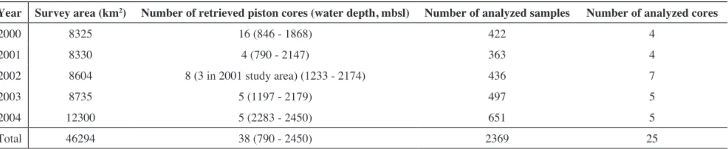
A total number of 38 piston cores with 5 - 8 m length were taken across the Ulleung Basin prior to the first drilling expedition in 2007 and here reported for the first time in a complete study (00GHP: 16 cores, 01GHP: 7 cores, 02GHP:
5 cores, 03GHP: 5 cores, 04GHP: 5 cores; Table 1). The cores were kept in the cold sample storage of the R/V TAMHAE-II at 4°C under constant humidity conditions immediately after their recovery and transported to the core repository at the KIGAM using a refrigerated car.
Cores were analyzed for (1) sedimentary textures and facies, (2) total organic carbon (TOC), carbon (C), hydro- gen (H), nitrogen (N), and sulfur (S), (3) the origin, com- position and concentration of residual hydrocarbon gases
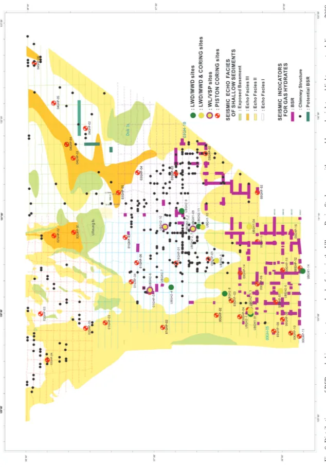
Fig. 2. UBGH site map depicting the location of drill sites, bathymetry, 2-D seismic lines collected in 2005, and 3-D survey areas (modified from Ryu et al. 2012).
in wet sediments, and (4) the depth of the sulfate-methane transition zone (SMTZ). In the laboratory at KIGAM, the cores were split and one half preserved as an archive and the other half processed as a working core. X-ray radiographs of 1 cm thick slabs were taken to analyze the sedimentary textures and facies.
Radiocarbon dating using foraminifera (14C) was per- formed by accelerator mass spectrometry (AMS) for sam- ples taken from two cores of the 2001 study region.
A total of 2369 samples were selected at 5 - 10 cm in- tervals from 25 cores collected from 2000 - 2004 (Table 1).
The samples were freeze-dried and ground to powders for further analyses. TOC contents of the sediments were mea- sured using the Rock-Eval pyrolysis technique that has often been used for the evaluation of the hydrocarbon source-rock potential of sedimentary rocks as shown by earlier studies (Tissot and Welte 1984; Peters 1986). N and S were also measured to determine TOC/N and TOC/S ratios, which are commonly used to determine the origin and depositional en- vironments of the organic matter in sediments (Stein 1991).
Elemental, and Rock-Eval pyrolysis analyses were per- formed using a LECO CHN-600 and a LECO SC-132, and a VINCI Rock-Eval-6 at KIGAM.
Concentrations of residual hydrocarbon gases in the cored sediments were analyzed using the headspace tech- nique. For the cores collected prior to publication of ODP Technical Note 30 by Pimmel and Claypool (2001), sam- ples were taken onboard after core recovery and immedi- ately placed with seawater into sealed cans as was the com- mon procedure on hydrocarbon exploration drill ships. For the cores retrieved in 2002 (01GHP-05 through 01GHP-07), two 5-cm3 samples were taken from each core onboard af- ter recovery and immediately placed into a 20-cm3 vial as described by Pimmel and Claypool (2001). In 2002, the samples were analyzed by both using a sealed can and a vial for comparison. There was no significant difference in the residual hydrocarbon gas results for the different sampling techniques. However, a total of 65 samples selected from 10 in 2003 and 2004 analyzed using a vial to follow the newly established ODP protocol.
Gas extracted from the head-space samples was in-
jected with a glass syringe into a Hewlett Packard HP 5890 II gas chromatograph (GC) at the KIGAM laboratory. The concentration of headspace gases was calculated using sample weight, total weight, sample volume, space volume, sediment volume, and pore water volume. Carbon isotopic compositions (δ13C) of the residual hydrocarbon gases were determined using isotope ratio mass spectrometry (IRMS) at the Korea Research Institute of Standard and Science (KRISS) using the same samples used for headspace gas analysis. The IRMS consists of a Hewlett Packard HP 6890 GC and a Finnigan MAT GC Combustion III, with analyti- cal reproducibility of ±0.4‰.
The concentrations of sulfate (SO42-) were analyzed to define the sulfate-methane transition zone (SMTZ) depths, which are used to estimate the upward methane fluxes (e.g., Borowski et al. 1996). Sulfate was analyzed using pore water extracted from two piston cores of the 00GHP study area as described by Gieskes et al. (1991) and immediately placed into the glass vial as described by Pimmel and Claypool (2001). These two cores were duplicated of cores 00GHP- 07 and 00GHP-14. The pore water was extracted from core samples by centrifuging for 30 min at 10000 rpm. The wa- ter was collected with a syringe and filtered using 0.45-μm membrane filters. Sulfate was analyzed using Dionex ion chromatography (DX-500 IC) with an AS-40 autosampler at the Seoul National University in Korea. The SMTZ of cores of the 01GHP study area were determined using the sulfate concentrations reported by Park et al. (2005).
Methods on analyzing deep drill cores taken during the drilling expedition UBGH1 and UBGH2 are described in Fugro (2007) and Ryu et al. (2012), respectively, and are not repeated here.
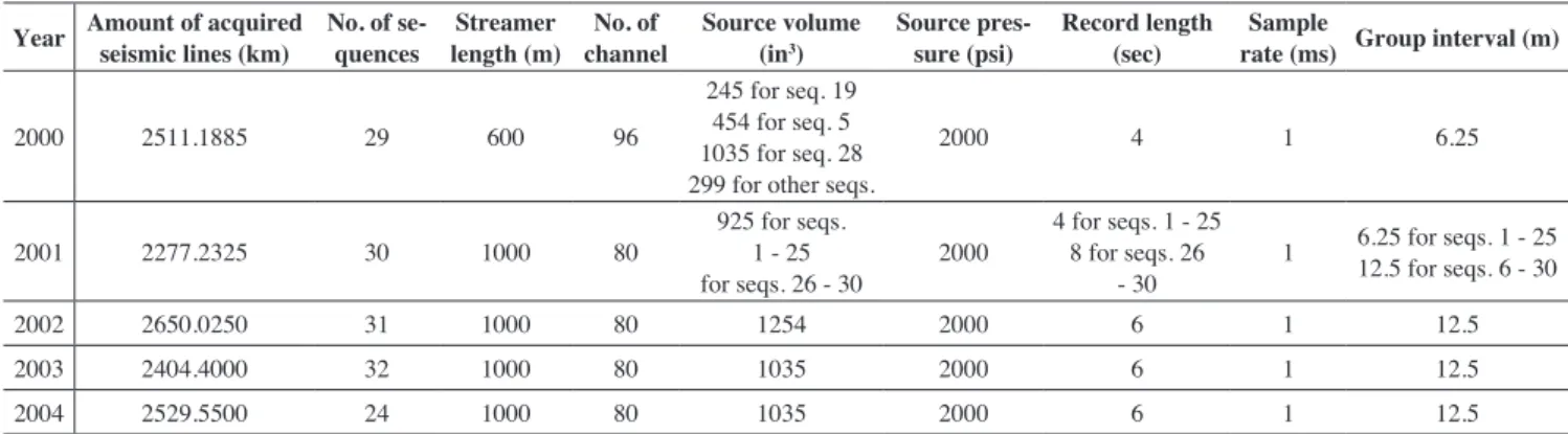
4.2 Geophysical Data Acquisition and Processing To determine the potential areas of gas hydrate accu- mulation in the jurisdictional sea of Korea, a total 12366 line-km 2D multichannel digital seismic data were acquired by using Trilogy System of Geco-Prakla and Bolt Air-gun System. Seismic data were processed to define the BSRs and seismic blank zones using Gecoseis, Geobit, Globe
Year Survey area (km2) Number of retrieved piston cores (water depth, mbsl) Number of analyzed samples Number of analyzed cores
2000 8325 16 (846 - 1868) 422 4
2001 8330 4 (790 - 2147) 363 4
2002 8604 8 (3 in 2001 study area) (1233 - 2174) 436 7
2003 8735 5 (1197 - 2179) 497 5
2004 12300 5 (2283 - 2450) 651 5
Total 46294 38 (790 - 2450) 2369 25
Table 1. Summary of piston cores and core analysis.
Note: mbsl: meter below sealevel.
Claritas, and ProMax. In addition, a total of 10491 line-km single channel seismic data were also acquired by using So- nar Enhancement System of GeoAcoustics and MESH200P hydrophone array of Benthos. The single channel seismic data were also processed by using SE881 Sonar Enhance- ment Work Station and version 3.5 software of GeoAcous- tics. The systematic processing of the multichannel seismic data included geometry definition and CMP sorting, band- pass filter, deconvolution, normal move-out correction (in iteration with semblance velocity analysis), stack, and time- migration. Single-channel data were processed only by in- cluding bandpass filters, deconvolution and time-migration using extrapolated (and assumed) velocity functions from the MCS data. Additionally, three 3D seismic data volumes totaling > 900 km2 (Table 2) were acquired for detailed analyses over key research areas (around Site UBGH1- 4 for detailed MTD analyses, across the seismic chimney structures and Sites UBGH1-9, UBGH1-10, UBGH2-2_1, UBGH2-2_2, and UBGH2-10).
Seismic data were mainly processed to define the re- gional distribution of BSRs and seismic blank zones (e.g., Ryu et al. 2004, 2009; Lee et al. 2005; Yoo et al. 2008, 2013;
Horozal et al. 2009) as primary indicators for gas hydrates.
The vertical extent of the GHSZ across the basin was defined either by using the BSRs or thermal modeling. The thermal modeling is based on seafloor temperatures measured with bathythermographs and sub-seafloor geothermal gradients measured with surface heat-probes (Huh et al. 2005). The gas hydrate phase equilibrium conditions were further de- fined based on results of head space gas analyses from cores recovered across the basin, results of ODP Leg 127, and as- sumed (or extrapolated) in situ pore-water salinities.
Reflection coefficients of the seafloor were estimated by Ryu et al. (2009) using the seafloor multiple method (Warner 1990) and the corresponding reflection coefficients for the BSR were then calculated using the reflection amplitude of the BSR and a conversion factor estimated from the seafloor reflection coefficients. These data were used to guide the
search for potentially high gas hydrate or free gas accumula- tions across the basin as well as to establish regional seismic velocity-depth functions that were utilized to define regional gas hydrate concentrations (Ryu et al. 2009). Additional spe- cialized seismic processing was performed on a subset of the available data with the aim to define possible concentrations of gas hydrate and free gas, with a focus on the reflection characteristics of BSRs. Special processing tools applied include amplitude-versus offset (AVO) analyses, full-wave- form inversion using the method shown by Yuan et al (1999), and band-limited impedance inversion (Grevemeyer et al.
2000) and were reported by Ryu et al. (2009).
4.3 Seismic- and Echofacies classification
Shallow sub-seafloor echofacies were defined across the Ulleung Basin and South Korea Plateau from 2D multi- channel seismic data collected from 2000 - 2004 (Ryu et al.
2004). The facies were classified using the reflection charac- teristics as means to differentiate individual classes and then linked to sedimentological and sediment character using all available core and drill data. Three main facies were defined:
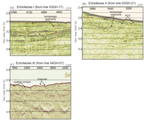
Echofacies I represents continuous and well stratified reflec- tions (Fig. 3a). Echofacies II is characterized by chaotic or transparent reflections, and echofacies III is defined by oc- currence of unconformities and channels (Figs. 3b and c).
5. rESULtS AND DIScUSSION
5.1 Geological and Geochemical Indicators for Gas Hydrate in cores
Gas hydrates contained in cored sediments is often largely dissociated due to pressure decrease and temperature increase upon recovery on deck. When gas hydrate dissoci- ates, it forms gas and (nearly) pure water that induces cracks and other disturbances in the sediment textures and freshen- ing of the pore waters. Results on these features from the drilling expeditions are reported in Fugro (2007); Ryu et al.
Year Amount of acquired seismic lines (km) No. of se-
quences Streamer length (m) No. of
channel Source volume
(in3) Source pres-
sure (psi) record length
(sec) Sample
rate (ms) Group interval (m)
2000 2511.1885 29 600 96
245 for seq. 19 454 for seq. 5 1035 for seq. 28 299 for other seqs.
2000 4 1 6.25
2001 2277.2325 30 1000 80 925 for seqs.
1 - 25
for seqs. 26 - 30 2000 4 for seqs. 1 - 25 8 for seqs. 26
- 30 1 6.25 for seqs. 1 - 25 12.5 for seqs. 6 - 30
2002 2650.0250 31 1000 80 1254 2000 6 1 12.5
2003 2404.4000 32 1000 80 1035 2000 6 1 12.5
2004 2529.5500 24 1000 80 1035 2000 6 1 12.5
Table 2. Acquisition parameters of 2D multi-channel seismic data analyzed for this study.
Note: in3: cubic inches.
(2012, 2013); Bahk et al. (2013a); and Kim et al. (2013d).
5.1.1 core Sedimentary textures
Cracks generally developed parallel to the bedding and were observed in the deeper intervals of cores 00GHP- 01, 00GHP-07, 00GHP-11, 01GHP-03, 03GHP-01, and 01GHP-01 (Fig. 4). The cracks are interpreted to have formed as a result of gas expansion upon recovery. Fluid- rich intervals with characteristic mousse-like textures from dissociating gas hydrates were also observed in these piston cores (Fig. 4).
5.1.2 tOc contents
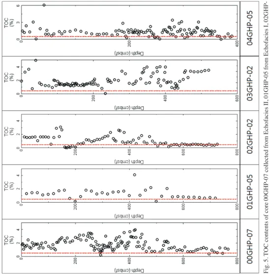
Total Organic Carbon (TOC) is an important indica- tor of the potential for substantial hydrocarbon gas genera- tion. In all piston cores, contents of TOC content ranged from 0.55 - 2.39% with an average value of 1.7% (Fig. 5).
A total of 2113 samples among 2369 samples (90% of ana- lyzed samples) show the TOC values above 0.5%. These results are sufficient for the formation of gas hydrate. Two intervals of core 00GHP-14 containing very low contents of TOC are mainly composed of coarser-grained sediments
(silt- and sand-sized). The organic matter in the sediments are originated from the marine algae, and deposited in an- oxic/euxinic environments
5.1.3 Sedimentation rates
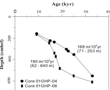
Sedimentation rates were defined for cores 01GHP- 04 and 01GHP-06 using the radiocarbon ages defined from AMS. The sedimentation rate showed a variation from 71 - 253 m/106 yr (mean: 168 m/106 yr), and from 62 - 640 m/106 yr (mean: 190 m/106 yr), respectively (Fig. 6). Considering that sedimentation rates should be higher than 30 m/106yr to form gas hydrate (Sloan 1998), we believe that the above results are sufficient in general for the formation of gas hydrate.
5.1.4 residual Hydrocarbon Gas concentrations Residual hydrocarbon gas concentration is an impor- tant indicator of the potential for formation of gas hydrate within the GHSZ. Sediments below the SMTZ as defined from some piston cores and UBGH2 drill cores showed generally higher concentration than 10 ml/l wet sediment (Fig. 7). These results indicate that the sediments have suf- ficient condition in order for gas hydrate to form following
(a) (b)
(c)
Fig. 3. Examples of three main echo facies defined from multichannel seismic data in the Ulleung Basin.
Fig. 4. Typical sediment textures with gas expansion cracks in recovered piston cores from the Ulleung Basin. Left panel: core 00GHP-11; right panel: core 03GHP-02. Left panel is from Ryu et al. 2009.
Fig. 5. TOC contents of core 00GHP-07 collected from Echofacies II, 01GHP-05 from Echofacies I, 02GHP- 02 from Echofacies III, 03GHP-02 from Echofacies II, and 04GHP-02 from Echofacies I. Red dotted line indicates 0.5% TOC.
Fig. 6. The variations of sedimentation rates of 01GHP-04 and 01GHP-06 recovered from the basin floor of the Ulleung Basin.
Fig. 7. Downhole profiles of methane and ethane in headspace gases. The red dash line indicates the sulfate-methane transition zone (SMTZ).
Note: BGHSZ: Base of Gas Hydrate Stability Zone.
the approach outlined by Sloan (1998). Spatial variations of residual hydrocarbon showed higher concentration in the southern part than in the northern part of the Ulleung Basin.
Also, residual hydrocarbon shows an increasing trend with sediment depth.
5.2 Gas composition
To clarify the gas source by the gas molecular com- positions, and to investigate gas migration pathways, head- space gas samples were collected and analyzed from the pis- ton cores (as well as all cores from the drilling expeditions, e.g., Choi et al. 2013). The hydrocarbon gases in sediments are mainly composed of methane, and minor amount ethane was detected (Fig. 7). C1/C2 ratio and carbon isotopic com- position of the methane (δ13CCH4) analyzed using piston and UBGH2 cores indicate that their origin is primarily biogenic (e.g., Sloan 1998).
5.3 Sulfate-Methane transition Zone
The analysis of sulfate concentrations from interstitial waters samples from the piston cores showed a variation of the sulfate-methane transition zone (SMTZ) depth between 3.2 and 13 mbsf, and an increasing trend with geographical latitude (Fig. 7). Thus, sulfate reduction, anaerobic methane oxidation, and methanogenesis are occurring at different depths in these cores basically as a function of the SMTZ- depths. Shallow sulfate reduction, and anaerobic methane oxidation occurred in cores 03GHP-01 and 03GHP-02 as their recovered core length (Table 3) reached well below the SMTZ. Methanogenesis occurs at greater depths within these two cores after all sulfate is depleted. Meanwhile, only sulfate reduction is dominant in all other cores because their recovered core length did not reach to the SMTZ (Fig. 7).
Therefore, the amounts of residual hydrocarbon are higher in cores 03GHP-01 and 03GHP-02 than in the other cores of the 2003 study region. These results suggest that reduction stage in the sediments with high residual hydrocarbon gas could be reached to the depth-interval where methanogene- sis is happening, whereas only sulfate reduction is dominant or methanogenesis is shifted to greater depths in the cores with low residual hydrocarbon. Overall, the SMTZ depths in the northern part of the basin are shallower than that in southern basin. It indicates that methane flux in northern basin is higher than in southern basin following basic model developed by Borowski et al. (1996).
5.4 Geophysical Indicators of Gas Hydrate 5.4.1 Seismic Velocity Structure and BSrs
Across the Ulleung Basin, BSRs were found in a num- ber of local patches (Fig. 8). They occur mainly in the south- ern part of the basin where mass flow deposits (echofacies
II) are widely developed. They also locally observed in the central part of the study area. However, it appears that in regions of dense occurrence of blank zones (chimneys), no clear BSR is developed. BSR-distribution maps for smaller sub-sets of seismic data across the Ulleung Basin were pre- viously published by Horozal et al. (2009) and Yoo et al.
(2013). Our regional coverage (Fig. 8) shows for the first time data north of the Ulleung Island and north of all drilling sites of UBGH1 and UBGH2.
The observed BSRs were characterized by (1) polarity reverse nature relative to the seafloor, (2) seafloor-parallel reflections at sub-bottom depth corresponding to the expect- ed base of gas hydrate stability zone (BGHSZ) as determined from thermal modeling, and (3) marked changes in seismic velocity, with slightly lower values below the BSR. These features are consistent with the BSR being produced by free gas accumulations trapped by gas hydrates at the BGHSZ.
The reflection coefficient of the BSR is useful for the esti- mation of the associated impedance and velocity contrasts, which provide some qualitative constraint on the amounts of gas hydrate and free gas (e.g., Fink and Spence 1999; Yuan et al. 1999). In low-frequency multichannel seismic data (60 - 80 Hz), the BSR reflection is consistent with a simple single interface model for the BSR, where the decrease in seismic impedance occurs over a depth range less than the seismic wavelength (about 30 m for the multichannel seis- mic data acquired in the Ulleung Basin average velocities of
~1800 m s-1 and dominant frequencies of ~60 Hz). In several areas, a velocity decrease below the BSRs was found by pre- stack semblance velocity analyses, although the concentra- tions of free gas are probably small. AVO studies (e.g., Yi et al. 2011), and band-limited impedance inversion constrained the velocity decrease to mostly < 100 m s-1 (Ryu et al. 2009) across the phase boundary for most examples studied.
In the southwestern part of the 2001 survey area at Site UBGH2-6, a strong lateral consistent BSR was observed as- sociated with an anticline structure. Here, the high reflection coefficients reported by Ryu et al. (2009) were confirmed by drilling to be the result of higher gas hydrate concentrations above the interface, with relatively small amounts of free gas (velocity decrease ~100 m s-1) beneath. However, the sedimentary layers in the study area are often bedded paral- lel to the seafloor (compare to discussion of seismic- and echofacies) so that the hydrate-related BSR may be hidden.
An important requirement for estimating gas hydrate and free gas concentrations from velocity data is the no hy- drate-/gas reference velocity-depth. For the reference veloc- ity-depth (Ryu et al. 2009) interpolated the trend at greater depths well below the BSR with velocity obtained near the seafloor where we assume that there is little hydrate expect- ed (except for chimney structures). That there is little hy- drate near the seafloor outside of chimney structures is well supported by well-log velocity data (Kim et al. 2008a, b, 2013a). The semblance-velocity method can be used best if
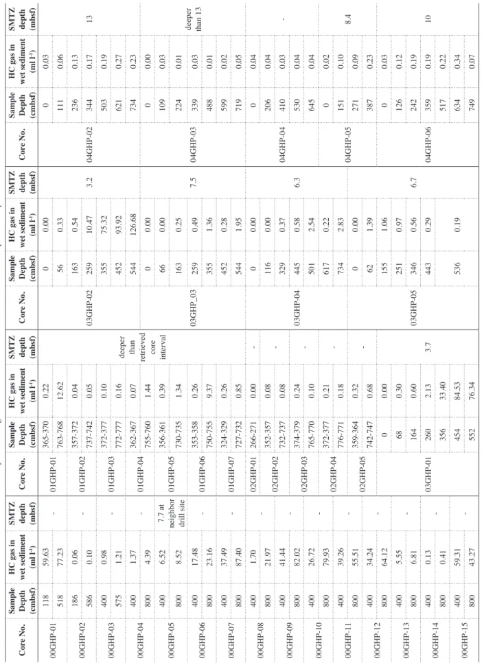
Table 3. Hydrocarbon gas concentrations in wet sediments and SMTZ depths of the piston cores. core No.
Sample Depth (cmbsf)
Hc gas in wet sediment (ml l-1)
SMtZ
depth (mbsf)
core No.
Sample Depth (cmbsf)
Hc gas in wet sediment (ml l-1)
SMtZ
depth (mbsf)
core No.
Sample Depth (cmbsf)
Hc gas in wet sediment (ml l-1)
SMtZ
depth (mbsf)
core No.
Sample Depth (cmbsf)
Hc gas in wet sediment (ml l-1)
SMtZ
depth (mbsf)
00GHP-0111859.63 -01GHP-01365-3700.22
deeper than retrieved
core interval
03GHP-02
00.00 3.204GHP-02
00.03 13
51877.23763-76812.62560.331110.06 00GHP-021860.06 -01GHP-02357-3720.041630.542360.13 5860.10737-7420.0525910.473440.17 00GHP-034000.98 -01GHP-03372-3770.1035575.325030.19 5751.21772-7770.1645293.926210.27 00GHP-044001.37 -01GHP-04362-3670.07544126.687340.23 8004.39755-7601.44 03GHP_03
00.00 7.504GHP-03
00.00
deeper than 13
00GHP-054006.52
7.7 at nei356-3610.39660.001090.03 ghbor 01GHP-05 8008.52730-7351.341630.252240.01drill site 40017.48353-3580.262590.493390.03 00GHP-06-01GHP-06 80023.16750-7559.373551.364880.01 40037.49324-3290.264520.285990.02 00GHP-07-01GHP-07 80087.40727-7320.855441.957190.05 4001.7002GHP-01266-2710.00- 00GHP-08- 03GHP-04
00.00 6.304GHP-04
00.04 -80021.97 02GHP-02352-3570.08 -1160.002060.04 00GHP-0940041.44 -732-7370.083290.374100.03 80082.02 02GHP-03374-3790.24 -4450.585300.04 00GHP-1040026.72 -765-7700.105012.546450.04 80079.93 02GHP-04372-3770.21 -6170.22 04GHP-05
00.02 8.400GHP-1140039.26 -776-7710.187342.831510.10 80055.51 02GHP-05359-3640.32 - 03GHP-05
00.00 6.7
2710.09 00GHP-1240034.24 -742-7470.68621.393870.23 80064.12 03GHP-01
00.00 3.7
1551.06 04GHP-06
00.03 10
00GHP-134005.55 -680.302510.971260.12 8006.811640.603460.562420.19 00GHP-144000.13 -2602.134430.293590.19 8000.4135633.40 5360.195170.22 00GHP-1540059.31 -45484.536340.34 80043.2755276.347490.07 Note: cmbsf: centimeter below seafloor; mbsf: meter below seafloor; HC gas: Hydrocarbon gas, SMTZ: Sulfate-Methane Transition Zone.
Fig. 8. Distribution map of BSRs and chimney structures, and echo-facies in the Ulleung Basin. Study areas with green, blue, red, violet, and light green track lines are 2000, 2001, 2002, 2003, and 2004, respectively.
the sediment sections are reasonably homogeneous laterally and on a seismic wavelength scale vertically, with velocity increasing smoothly with depth (time). A stated by Ryu et al. (2009), the reference velocity-depth function was found to be quite constant for large regions of the deep Ulleung Basin, which is also reflected in the nature of the uppermost seismic facies defined (see discussion below). The regional velocity-depth relation defined by Ryu et al. (2009) are in general agreement with those from OBS refraction seismic experiments in the region according to Kim et al. (1998) and well-log data acquired during UBGH1 and UBGH2.
Significant deviations from this reference velocity-depth profile may be interpreted as due to high velocity gas hy- drate or low velocity free gas, although velocity variations due to lateral changes in sediment type [e.g., in regions of wide-spread mass-transport deposits, where sediment con- solidation cannot be excluded (see discussion in Riedel et al. 2012)]. A different approach to defining a reference pro- file was shown by Kim et al. (2013b) using effective me- dium modelling for well-log data from UBGH2, based on core-derived distributions of the mineralogy to calculate a site-specific hydrate-free background trend.
5.4.2 Seismic- and Echofacies of the Sedimentary Strata Using facies classification of seismic or acoustic sub- bottom profiler data is a common approach in regional re- source assessments. The principle goal of facies classifica- tion is the reduction of seismic data (with complex phase and amplitude information) to simple groups of “similar- looking” data. Several such studies were undertaken for the Ulleung Basin in the past. Using probabilistic classifica- tion tools, Kang et al. (2012) defined five seismic facies, which were then verified with the LWD and wire-line log data from the drilling expeditions and incorporated into a resource-type assessment (see section 5.5 for details). Addi- tional seismic facies classifications were carried out by Rie- del et al. (2013a, b) for a sub-set of the seismic data and well sites with an aim to improve seismic-based estimation of hydrate concentrations. Yoo et al. (2013) also used seismic facies classifications for resource estimation, and classified the seismic facies into five facies using reflection pattern such as stratified and chaotic, and strength of amplitude.
Here, we present a map of regional echofacies clas- sification (Fig. 8) using the 2D multichannel seismic data collected from 2000 - 2004. The sedimentary strata in the Ulleung Basin and South Korea Plateau located north of the Ulleung Basin are classified into three echofacies in terms of the seismic reflection signatures (Figs. 3 and 8). Echofa- cies I is characterized by continuous, well-stratified reflec- tions and sheet-shaped sediment depositional geometries (Fig. 3a). This facies unit is present in the strata of a low-gra- dient slope or the upper strata of the central basin. The region of echofacies I also includes a region of acoustic structures
of pock marks and chimney structures in the center of the basin. The unit is interpreted as alternations of very thin tur- bidite and hemipelagic deposits. Echofacies II mainly occurs in strata at the base of the continental to the south and west of the basin (Fig. 8). The facies unit II represents discontinu- ous, chaotic or transparent seismic reflection configurations (Fig. 3b). This unit contains commonly hummocky facies in various scales, and is generally very thick. This facies unit partly includes thin layers of stratified reflections. This unit is interpreted as debrites or volcanic or volcanoclastic flow deposits. Echofacies III occurs around the Korea Gap (Fig. 8), and is characterizing by strong erosion from bottom currents or turbidity (or debris) flows (Fig. 3c).
5.5 resource Assessments, Production test Model, and Geotechnical Properties
Only few sand layers with gas hydrate were recovered during the two drilling expeditions within the Ulleung Basin (Ryu et al. 2012, 2013; Bahk et al. 2013a, b). Resource as- sessments type studies were subsequently conducted using the drilling data combined with 2D (Riedel et al. 2013a, b) and 3D seismic data (Kim et al. 2015, 2017) in smaller sub- regions of the basin. A basin-wide assessment was carried out by Ryu et al. (2014). Using Monte Carlo simulations, a resource assessment was performed based on WL/VSP data from three sites (one UBGH1 site and two UBGH2 sites), results of core analyses from 13 sites (three UBGH1 sites and ten UBGH2 sites), 6690 km of 2D multichannel reflec- tion seismic lines collected in 2005, and 700 km2 of 3D seis- mic data acquired in 2006 and 2008 (Ryu et al. 2013). Five facies were classified based on seismic facies, lithofacies, log facies, and results of core analyses and gas hydrate satu- ration values (Sh). Each facies was characterized by various parameters (total volume, porosity, net to gross ratio, Sh, cage occupancy, and volume ratio). The ratios of net thick- ness of gas hydrate-bearing sand layers to the total thickness of gas hydrate-bearing intervals were determined following the approach of Fujii et al. (2008). The targets of the produc- tion test in the Ulleung Basin are gas hydrate-bearing sand layers, which were identified from the UBGH2 sites and are regarded as recoverable resource with existing technologies (Boswell 2009). The in-place gas hydrate resource volume within the sand reservoirs was additionally assessed. The total amount of mean in-place gas resource contained in the gas hydrates within the survey area was estimated to be 58.75 trillion cubic feet (tcf). The mean in-place gas hydrate resource volume within the sand reservoirs was estimated to be 31.16 tcf. Using the data from the two drilling expe- ditions, significant improvements of the understanding of changes in sediment physical properties due to production were made. Lee et al. (2013) showed that subsidence in- duced by pore pressure changes as result of depressurization would be greater than changes induced by the loss of gas
hydrate in the reservoir itself. They also predicted signifi- cant vertical deformation in fine-grained sediment layers as a response to the pore pressure changes from depressuriza- tion. They further highlighted concerns associated with low fracture gradients in these shallow sedimentary sections.
As shown by an earlier study (Kim et al. 2013c), the fine- grained sedimentary sections were classified as high plastic silty soils according to the Unified Soil Classification Sys- tem (USCS); they exhibited high compressibility when sub- jected to an increase in effective stress (or a decrease in pore water pressure) and had low hydraulic conductivities and low pressure diffusion coefficients. Similar to the analyses by Kim et al. (2013c) and Lee et al. (2013) predicted that the application of depressurization for gas hydrate production would cause a significant amount of sediment compaction.
Lee et al. (2013) documented that the sediments in the basin consists mineralogically of illite, kaolinite, chlorite, calcite, and montmorillonite, with a high concentration of micro- fossils (diatoms). They also argue that the presence of mi- crofossils may affect many of the geotechnical properties, including plasticity, activity, surface area, and grain size.
Following these fundamental analyses, several model scenarios for potential production were computed for the region around Site UBGH2-6 (Moridis et al. 2014). Mod- eling of the short-term (14 day) and long-term production tests focused (among other scenarios) on the expected gas production rates and the possibility of subsidence and geo- mechanical stability around the wellbore and within the res- ervoir, coupled with an overall sensitivity analysis of the assumed gas hydrate system to various flow, thermal, and geomechanical properties of the sediments.
6. cONcLUSIONS
The studies on gas hydrates in the deep-water Ulleung Basin, East Sea of Korea using geophysical data, shallow coring, deep drilling, resource assessments, and gas hydrate production modeling, have given the following general re- sults:
(1) Geological and geochemical data of shallow piston cores as well as cores taken during deep drilling support the general interpretation of wide-spread gas hydrate oc- currence in the Ulleung Basin. In cores, high amounts of total organic carbon (TOC) and high core headspace gas indicate generally favorable conditions for gas hy- drate formation in the shallow sediments. The lack of higher hydrocarbons and the δ13CCH4 values indicate that the methane is primarily of biogenic origin. The SMTZ depths are shallower in the northern basin than within the southern basin, suggesting higher methane fluxes in the northern region. TOC/N and TOC/S ratios and δ13Corg values of the core sediments indicate that organic matters are dominantly originated from marine algae.
(2) Bottom-simulating reflectors (BSRs) were identified
across the Ulleung Basin from a dense grid of 2 D seis- mic data by (a) polarity reversed nature relative to the seafloor, (b) seafloor-parallel reflection behavior, and (c) occurrences at a sub-bottom depth corresponding to the expected BGHSZ. Their occurrences are patchy and the reflection amplitude is generally low indicating small amounts of free gas below the BGHSZ. The BSRs were used primarily as general guide for mapping gas hydrate occurrences within the basin, but are not the only direct gas hydrate indicator in the region.
(3) Vertical to sub-vertical seismic blanking zones are well observed throughout the Ulleung Basin. The blank- ing zones (with more than 250 structures identified on 2D seismic lines alone) are near-vertical broad chim- ney structures of reduced sediment layering reflectiv- ity. They may be formed by gas and/or fluid upwelling through fractures and faults. Many of the blanking zones show apparent velocity pull-up structures in time-mi- grated seismic data which are interpreted to be a result of higher velocity gas hydrate. The presence of substantial amounts of gas hydrates in the blanking zones was con- firmed by piston coring in 2007, and two drilling expedi- tions in 2007 and 2010. The blanking zones mainly oc- cur in the hemi-pelagic/turbidte facies developed in the central part of the basin. They also are locally observed in the northern basin (e.g., Site UBGH2-7) or isolated along the southern edge of the basin (e.g., Site UBGH2- 3). Although no production technology has yet been identified for these chimney structures, they represent, when regionally combined, the largest accumulation of gas hydrate in the Ulleung Basin and thus, may represent a valuable resource.
(4) To characterize the distribution of gas hydrate indicators in the Ulleung Basin, shallow echofacies and seismic facies were analyzed based on seismic reflection sig- natures. These echofacies reflect regional depositional characters and sediment distribution and were facilitated in regional resource assessments.
(5) Gas hydrate saturations were determined from geo- physical well-log data as well as pore-water chemistry and core infra-red imaging. Saturation estimates vary significantly between drill/core sites, but are generally consistent at each individual site between acoustic and resistivity-based approaches.
(6) The combined use of geophysical image logs and pres- sure coring revealed that gas hydrate occurs in a fracture network within the seismic blanking zones. Saturation estimates from well-logs have to consider the anisotropy effect imposed by the near-vertical fracture network be- ing parallel to the vertical well-log tool measurements.
(7) The dense grid of 2D seismic profiles across the basin, combined with the coverage of multibeam and high-res- olution echosounder data in conjunction with two com- prehensive drilling expeditions allowed careful resource
assessments for the Ulleung Basin. Facies classification, complete core-log-seismic integration, and petroleum system modeling demonstrated a potential of the Ulle- ung Basin to host substantial amounts of gas hydrates.
7. FUtUrE rESEArcH AND DIrEctION
With the successful completion of the UBGH2, the primary goals of the gas hydrate development project were sufficiently accomplished. A production test primarily was planned to be performed in 2015. For safer and more suc- cessful testing, additional studies of seafloor stability, rehy- dration and sand-production problems are required. Thus, the production test has been postponed to the period of the 2nd gas hydrate R&D program that is currently being planned.
To develop the most suitable techniques for the production, experimental researches will be performed using a 3D m- scale simulator. To ensure safe and environmental friendly production testing, environmental impact studies including baseline and monitoring surveys have been and will con- tinue to be performed in the future. A first baseline survey has been performed using the KIGAM Seafloor Observa- tion System (KISOS). To monitor the various potential haz- ards associated with the dissociated gas from gas hydrates, a monitoring survey will be performed using the KIGAM Seafloor Monitoring System (KIMOS) during the proposed production test. Geophysical surveys for determining any changes of the gas hydrate reservoirs and production-effi- ciency around the production well will also be conducted before and after the production test.
Acknowledgements This paper was supported by the re- search project of the Korea Institute of Geoscience and Min- eral Resources (Gas Hydrate Exploration and Development Study) supported by the Ministry of Science, ICT and Fu- ture Planning (currently Ministry of Science and ICT). We sincerely thank the scientists and technical staffs working for this gas hydrate project at the KIGAM, and crew of R/V TAMHAE II responsible for the geophysical data acquisition and core recovery.
rEFErENcES
Archer, D., 2007: Methane hydrate stability and anthropo- genic climate change. Biogeosciences, 4, 521-544, doi:
10.5194/bg-4-521-2007. [Link]
Bahk, J. J., D. H. Kim, J. H. Chun, B. K. Son, J. H. Kim, B. J. Ryu, M. E. Torres, M. Riedel, and P. Schultheiss, 2013a: Gas hydrate occurrences and their relation to host sediment properties: Results from Second Ulle- ung Basin Gas Hydrate Drilling Expedition, East Sea.
Mar. Petrol. Geol., 47, 21-29, doi: 10.1016/j.marpet- geo.2013.05.006. [Link]
Bahk, J. J., G. Y. Kim, J. H. Chun, J. H. Kim, J. Y. Lee, B.
J. Ryu, J. H. Lee, B. K. Son, and T. S. Collett, 2013b:
Characterization of gas hydrate reservoirs by integra- tion of core and log data in the Ulleung Basin, East Sea. Mar. Petrol. Geol., 47, 30-42, doi: 10.1016/j.mar- petgeo.2013.05.007. [Link]
Borowski, W. S., C. K. Paull, and W. Ussler, 1996: Ma- rine pore-water sulfate profiles indicate in situ methane flux from underlying gas hydrate. Geology, 24, 655- 658, doi: 10.1130/0091-7613(1996)024<0655:MPWS- PI>2.3.CO;2. [Link]
Boswell, R., 2009: Is hydrate energy within reach? Science, 325, 957-958, doi: 10.1126/science.1175074. [Link]
Boswell, R. and T. S. Collett, 2011: Current perspectives on gas hydrate resources. Energy Environ. Sci., 4, 1206- 1215, doi: 10.1039/c0ee00203h. [Link]
Choi, J., J. H. Kim, M. E. Torres, W. L. Hong, J. W. Lee, B.
Y. Yi, J. J. Bahk, and K. E. Lee, 2013: Gas origin and migration in the Ulleung Basin, East Sea: Results from the Second Ulleung Basin Gas Hydrate Drilling Expe- dition (UBGH2). Mar. Petrol. Geol., 47, 113-124, doi:
10.1016/j.marpetgeo.2013.05.022. [Link]
Chough, S. K. and E. Barg, 1987: Tectonic history of Ulleung basin margin, East Sea (Sea of Japan). Geology, 15, 45- 48, doi: 10.1130/0091-7613(1987) 15<45:THOUBM>
2.0.CO;2. [Link]
Chough, S. K., H. J. Lee, and S. H. Yoon, 2000: Marine Geology of Korean Seas, 2nd Ed., Elsvier, Amsterdam, 313 pp.
Collett, T. S., A. H. Johnson, C. C. Knapp, and R. Boswell, 2009: Natural Gas Hydrates: A Review. Natural Gas Hydrates—Energy Resource Potential and Associated Geologic Hazards, AAPG Memoir 89, 146-219.
Collett, T. S., M. Riedel, R. Boswell, J. Presley, P. Kumar, A. Sathe, A. Sethi, and M. V. Lall, 2015: Indian Na- tional Gas Hydrate Program Expedition 01 report.
Scientific Investigations Report 2012-5054, U.S. Geo- logical Survey, Reston, VA, 1442 pp, doi: 10.3133/
sir20125054. [Link]
Fink, C. R. and G. D. Spence, 1999: Hydrate distribution off Vancouver Island from multifrequency single-channel seismic reflection data. J. Geophys. Res., 104, 2909- 2922, doi: 10.1029/98JB02641. [Link]
Furo Mcclelland Marine Geosciences, Inc., 2007: Investi- gation of Gas Hydrate Expedition UBGH1, Ulleung Basin, East Sea offshore Korea, Factual Field Report No. 0201-6242.
Fujii, T., T. Saeki, T. Kobayashi, T. Inamori, M. Hayashi, O. Takano, T. Takayama, T. Kawasaki, S. Nagakubo, M. Nakamizu, and K. Yokoi, 2008: Resource assess- ment of methane hydrate in the eastern Nankai Trough, Japan. Proceedings of Offshore Technology Confer- ence, OTC-19310-MS, Houston, Texas, USA , doi:
10.2118/19310-ms. [Link]
Gardner, J. M., A. N. Shor, and W. Y. Jung, 1998: Acoustic