1. Introduction
Submarine landslides can be several orders of magnitude larger than their terrestrial counterparts (Korup et al., 2007), and can have devastating and widespread consequences. The submarine landslide itself could
Abstract
Submarine landslides can be several orders of magnitude larger than their terrestrial counterparts and can pose significant hazards across entire ocean basins. The landslide failure mechanism strongly controls the associated tsunami hazard. The Tampen Slide offshore Norway is one of the largest landslides on Earth but remains poorly understood due to its subsequent burial beneath up to 450 m of sediments. Here, we use laterally extensive (16,000 km2), high-resolution processed 3-D seismic reflection data to characterize the upper Tampen Slide. We identify longitudinal (downslope, movement-parallel) chutes and ridges that are up to 40 m high, as well as extensional and compressional (cross-slope) ridges.This is the first time that longitudinal ridges of such size have been imaged in a deep marine setting. The first phase of the Tampen Slide involved the simultaneous translation of over 720 km3 of sediments along a single failure plane. This was followed by spreading along the head- and sidewall, and the formation of a retrogressive debris flow and slump, the volumes of which are insignificant compared to the first failure. The process responsible for movement of such a large sediment volume along a single glide plane differs significantly from that of other passive margin megaslides, which typically comprise numerous smaller landslides that fail retrogressively along multiple glide planes. The trigger mechanism (e.g., an earthquake), the presence of mechanically strong obstructions (e.g., volcanic structural high), and the number and location of weak layers may be key factors that determine whether megaslides develop along a single plane or retrogressively.
Plain Language Summary
Submarine landslides can be significantly larger than those that occur on land and can cause damaging and widespread tsunami. Furthermore, submarine landslides can also damage critical offshore infrastructure, including telecommunication cables that now carry >95%of global data traffic. However, we still lack fundamental understanding about how such landslides fail.
This is critical to understand because it determines the magnitude of associated tsunami. Here, we use exceptionally detailed 3-D seismic data to understand how one of the largest landslides on Earth, the Tampen Slide offshore Norway, failed. We find that the Tampen Slide failed mainly as a single volume along a single failure surface. This differs significantly from how other giant submarine landslides seem to have failed: in multiple phases and involving multiple failure surfaces that migrated upslope. This was thought to be the only way that giant submarine landslides developed, with multiple smaller landslides accounting for the large total volume. Here, we show for the first time that large submarine landslides can also fail along a single surface across an extensive area, possibly favoring generation of particularly large tsunami. Other large submarine landslides may also fail similarly, and this new model should be included in future hazard assessments.
© 2020. The Authors.
This is an open access article under the terms of the Creative Commons Attribution-NonCommercial-NoDerivs License, which permits use and distribution in any medium, provided the original work is properly cited, the use is non-commercial and no modifications or adaptations are made.
the Tampen Slide, Offshore Norway
R. S. Barrett1 , B. Bellwald2 , P. J. Talling3 , A. Micallef 4,5 , F. Gross1,6 , C. Berndt5 , S. Planke2,7, R. Myklebust8, and S. Krastel1
1Institute of Geosciences, Christian-Albrechts-University, Kiel, Germany, 2Volcanic Basin Petroleum Research AS, Oslo, Norway, 3Departments of Earth Sciences and Geography, Durham University, Durham, UK, 4Marine Geology
& Seafloor Surveying, Department of Geosciences, University of Malta, Msida, Malta, 5GEOMAR Helmholtz Centre for Ocean Research Kiel, Kiel, Germany, 6Center for Ocean and Society, Kiel Marine Science, Christian-Albrechts- University, Kiel, Germany, 7Centre for Earth Evolution and Dynamics, University of Oslo, Oslo, Norway, 8TGS, Asker, Norway
Key Points:
• We use high-resolution processed 3-D seismic data to characterize the headwall of the Tampen Slide, one of the largest landslides on Earth
• The first phase of the Tampen Slide involved the simultaneous translation of more than 720 km3 of sediments along a single failure plane
• Our model shows that retrogression (bottom-up development) may not account for the large volumes of all giant submarine landslides
Supporting Information:
• Supporting Information S1
Correspondence to:
R. S. Barrett,
rachel.barrett@ifg.uni-kiel.de
Citation:
Barrett, R. S., Bellwald, B., Talling, P. J., Micallef, A., Gross, F., Berndt, C., et al. (2021). Does retrogression always account for the large volume of submarine megaslides? Evidence to the contrary from the Tampen Slide, offshore Norway. Journal of Geophysical Research: Solid Earth, 126, e2020JB020655. https://doi.
org/10.1029/2020JB020655 Received 27 JUL 2020 Accepted 21 DEC 2020
destroy critical seabed infrastructure, while an associated tsunami could inundate coastlines across ocean basins, impacting communities, global economies, and seabed ecosystems (Lintern et al., 2018, and refer- ences therein). The way in which a landslide fails strongly determines the scale of an associated tsunami (e.g., Harbitz et al., 2014; Løvholt et al., 2017), and direct hazards to seabed infrastructure. Retrogression, a process whereby failure initiates at the base of the slope and migrates upslope, is widely thought to be the main mechanism by which the largest volume landslides (“megaslides”) develop on passive margins (Masson et al., 2010). The large total volume of these megaslides is typically the result of numerous smaller retrogressive failures, involving multiple headwalls that cut down to different failure (“glide”) planes (e.g., Antobreh & Krastel, 2007; Georgiopoulou et al., 2010; Hill et al., 2019; Kvalstad et al., 2005; Laberg & Vor- ren, 2000; Vanneste et al., 2006). The Storegga Slide that occurred roughly 8,100 years ago offshore Norway (Figure 1) is one of the largest landslides on the planet and involved a total volume of 2,400–3,200 km3, which failed retrogressively in tens of phases, along multiple glide planes (Haflidason et al., 2004; Kvalstad et al., 2005; Micallef et al., 2009). The resulting tsunami inundated coastlines across the North Sea, with a runup of up to 25 m at the Shetland Islands (Bondevik et al., 2005).
The Tampen Slide, an older and perhaps even larger submarine megaslide, is located in a similar position to the Storegga Slide on the Norwegian continental margin (Figure 1). However, the failure mechanism of the Tampen Slide remains poorly understood. Consequently, the hazard associated with the failure of a similar megaslide is poorly constrained. This is largely due to its subsequent burial under up to 450 m of glacigenic sediment (Figure 2; Bellwald et al., 2020), and partial remobilization by the Storegga Slide. Several previous studies have analyzed the character of the Tampen Slide (Evans et al., 1996; Gafeira et al., 2010; Hjelstuen &
Grinde, 2016; Nygård et al., 2005). These studies, however, are based on widely spaced 2-D seismic profiles, and local 3-D seismic surveys, and the character of the Tampen Slide deposits and glide plane within the headwall region remain poorly constrained.
Here, we make use of extensive (∼16,000 km2), high-resolution processed 3-D seismic reflection data that cover the headwall area of the Tampen Slide. We characterize the megaslide's morphology, and thereby un- derstand its emplacement mechanism. We then compare the Tampen Slide with other megaslides on passive Figure 1. (a, b) The location of the buried Tampen Slide headwall within the North Sea Fan, offshore Norway and (c) an overview of the location of data sets used in the previous studies of the Tampen Slide. Note that the full lateral extent of the Tampen Slide is unknown. Regional volcanic escarpments after Zastrozhnov et al. (2020). FSE: Faroe-Shetland Escarpment, the eastern boundary of the volcanic Møre Marginal High.
8˚W 8˚E
64˚N68˚N
3600 Depth [m] 0
North SeaFan
Norwegian Channel Shetland Is.
Faroe Is.
Study location Volcanic escarpments
Storegga Slide (full extent) Tampen Slide
100 km
N
Voring Plateau
Norway Fig. 1c
b
c
a
50 km Gafeira et al. (2010);
Bull et al. (2009)
N Tampen Slide
remnants
North Sea Fan Nyga
rd et al. (20 05);
Bellwal d et al.
(2019 )
Hjelstuen & Grinde (2016) Figs.
3 & 4
Tampen Slide sidewall
FSE
Fig. 2 FSE
Other 3D studies This study 2D seismic profiles Key:
?
?
Tampen Slide headwall
margins, and determine if there are significant differences in their emplacement mechanisms. We discuss possible reasons for these differences, and their implications for tsunami generation and geohazards.
2. Geological Setting
The Tampen Slide occurred within the deposits of the North Sea Fan offshore Norway (Figure 1) --a trough mouth fan that comprises downslope-related sediments (flow deposits that accumulated very rapidly at the termination of an ice stream), and along-slope-related sediments (contourites) that accumulated between ice sheet advances (Bellwald et al., 2020; Nygård et al., 2005). In addition, multiple submarine landslides are found within the North Sea Fan, several of which have total volumes exceeding 1,000 km3 (Hjelstuen &
Grinde, 2016; King et al., 1996; Nygård et al., 2005). The most recent of these megaslides, the Storegga Slide, is exposed at the seafloor and occurred 8,100 years ago (Haflidason et al., 2005). The timing of megaslides offshore Norway has been suggested to correspond with the transition from a glacial to an interglacial peri- od (Bryn et al., 2005). In this model, the occurrence of megaslides correlates strongly with glacial cycles: the slides are preconditioned by sedimentary loading during glacial periods, which leads to the development of overpressure, before failure is triggered by a large earthquake following the retreat of the Fennoscandian ice sheet and as a result of isostatic rebound (Bellwald et al., 2019; Bryn et al., 2005; Kvalstad et al., 2005).
The giant Tampen Slide is buried beneath up to 450 m of glacigenic sediments and contourites within the North Sea Fan (Figure 2). In keeping with the previous model (Bryn et al., 2005) and based on the results Figure 2. Seismic section crossing the headwall of the Tampen Slide, showing (a) migrated data and (b) interpretation.
Note that the Tampen Slide is overlain by up to 450 m of glacigenic sediments and contouritic deposits. The location of this profile is shown by the black line in the inset panel. See Figure 1 for the location of the Tampen headwall. VE:
Vertical Exaggeration. Profile from the AMS17 Vol. A data set and courtesy of TGS.
of numerical modeling along a 2-D profile within the headwall region, Bellwald et al. (2019) suggest that the Tampen Slide was preconditioned by the rapid deposition of glacial sediments and then triggered by an earthquake near its headwall. Its headwall is bound by the Norwegian continental shelf on its eastern and southern sides, and by the volcanic Møre Marginal High on the west (Figure 1). The Møre Marginal High is one of a series of volcanic structural highs offshore Norway, and its eastern boundary is known as the Faroe-Shetland Escarpment (Kiørboe, 1999). The subsequent Storegga Slide remobilized Tampen Slide deposits west of the Tampen Slide's headwall area (Figure 1). This burial and remobilization of the Tam- pen Slide deposits have hindered its investigation. Previous studies have suggested that the Tampen Slide mobilized a total of 1,400 km3 of sediment (Nygård et al., 2005), but this estimate is based on widely spaced 2-D seismic reflection profiles, and is thus associated with significant uncertainty. The estimated age of the Tampen Slide (∼130 ka; Nygård et al., 2005) is also based on regional seismic correlation and is thus poorly constrained (Pope et al., 2018; Watts et al., 2016).
3. Data and Methodology
We make use of 3-D migrated seismic reflection data (AMS17; Figure 1) that were acquired by TGS in 2017.
These data cover an area of ∼16,000 km2, and were collected using a triple-sourced airgun array with a total volume of 3,000 in3 and a shot point interval of 12.5 m. The acquisition system consisted of 12 streamers separated by 112.5 m. The streamers were 8,100 m long and were towed in water depths of 7–12 m.
The two seismic volumes used in this study are as follows: i) Volume A, which has 4 ms sampling and 12.5 × 18.75 m bin size (∼8 m vertical and ∼20 m horizontal resolution); and ii) Volume B: a shallow, high resolution volume with a 2 ms sample rate and 6.25 × 18.75 m binning (∼2 m vertical and ∼10 m horizontal resolution). Volume B was processed with the aim of increasing the resolution of shallow targets and haz- ards. However, this volume only extends to the first multiple, which cuts through the base of the Tampen Slide near its eastern headwall.
The upper and lower surfaces of the Tampen Slide were picked at roughly 150 m increments using the soft- ware IHS Kingdom. The bounding surfaces were defined as the highest amplitude peak that corresponds with the horizons immediately overlying and underlying the slide deposits (Figure 2). In regions with a higher amount of morphologic variation, picking was conducted at higher density, and included the inter- pretation of crosslines. The interpreted lines were gridded using continuous curvature splines with adjusta- ble tension (GMT 5.4.5 “surface” routine; Smith & Wessel, 1990), and the grid was snapped to the maximum amplitude within a vertical window of 10 ms centered on the picked horizon. The structure and amplitude maps, as well as the seismic profiles, were then used for geomorphological analysis of the slide. Two-way travel time (TWT) was converted to depth using a uniform velocity of 1,700 m/s (after Nygård et al., 2005), in order to calculate the thickness of units.
4. Results: Morphology of the Tampen Slide
The horseshoe-shaped main headwall of the Tampen Slide extends for >350 km, and encompasses an area
>25,500 km2 (Figure 1). The main headwall is up to 250 m high, and is encircled by a secondary headwall step that was first identified by Nygård et al. (2005) and is typically <100 m high (Figures 2 and 3). A large amount of failed material (∼845 km3) remains within the surveyed region of the Tampen Slide's headwall.
In the following sections, we describe the morphology of the Tampen Slide's basal surface (glide plane) and the deposits that remain within the surveyed region of the headwall.
4.1. The Glide Plane
The Tampen Slide's glide plane follows underlying stratigraphy and, similarly to other submarine megas- lides, dips gently (<1° on average) north-northwest, except at the southwest corner of the headwall where it domes over a local basement high (Figure 4). The maximum amplitude map of the basal plane (Figure 4b) is dominated by high amplitudes along the western sidewall. The central region of the Tampen Slide's ba- sal plane is characterized by medium to low amplitude stripes (>20 km wide) that are aligned downslope.
The glide plane is largely smooth, although there are parallel linear scours along the western side of the
headwall and within the western-central region of the headwall, and parallel steps in the northern reaches of the surveyed region (Figures 4 and 5).
The parallel linear scours along the western side of the headwall (Figure 4a) correspond to overlying pat- terns of deformation (linear ridges) within the slide debris (Figure 6). The erosional scour marks within the western-central region of the headwall correspond with a change in the maximum amplitude of the glide plane (Figure 4b), as well as with a variation in the nature of the overlying slide deposits. The slide deposits Figure 3. Upper surface of the Tampen Slide: (a) two-way travel time (TWT) and (b) maximum amplitude within a 10 ms vertical window of the picked TWT horizon. Note that the band of high amplitudes through the northern-central region of the slide deposits corresponds with where the deposits are thinner (see Figure 9). Locations of subsequent figures are indicated by the overlays. Small arrows: slope direction of the glide plane; white dashed line: Faroe-Shetland Escarpment (FSE); VE: Vertical Exaggeration. (c) Geomorphologic map highlighting the main types of debris within the Tampen Slide headwall region. A regional pseudo-3-D cube (J-Cube MN; Whiteside et al., 2013) was used to extend the headwall of the Tampen Slide beyond the limits of AMS17. Data from AMS17 Vol. B and courtesy of TGS.
TWT [s] 0.4 2.7
Tampen Slide upper surface
Unfailed
Chutes Lateral-offset faults
Spreading on Tampen’s upper headwall step (Hjelstuen & Grinde, 2016) Compressional ridges
Tampen’s main headwall
Fig. 6
Fig. 7 Fig.
2
Upper headwall step
Unfailed Fig. 9 FSE
20 km
N
VE =10 45°
Shader direction
Spreading along sidewall Unfailed material
Spreading along headwall step
Subsequent failures Chutes
Central region of Tampen Slide
Longitudinal ridges
Fig. 8
Max. Ampl. [10 ms]Low High
Tampen Slide upper surface
Unfailed
Chutes Lateral-offset faults
Compressional ridges Tampen’s main
headwall
Fig. 6
Fig. 7
Upper headwall step
Fig. 9 FSE
20 km VE =0
Longitudinal ridges N
Multiple artefact Spreading
ridges
N 20 km Unfaile
d
Tampen’s main headwall
b a
c
to the west of this divide are characterized by linear ridges, orientated parallel to the headwall, and with vis- ible internal horizons (discussed in Section 4.2). East of this divide, the internal structure of the slide debris is chaotic with no mappable internal horizons. In the northern reaches of the headwall region, the glide plane steps down to a lower stratigraphic level and then back up again across two parallel steps (Figure 5).
4.2. Extensional Ridges Along the Western Sidewall and on the Upper Headwall Step
Along the western sidewall, elongated ridges are aligned parallel to the headwall scarp (Figures 3 and 6).
The interior of these ridges is increasingly chaotic with distance from the scarp (eastwards) (Figure 6), and associated deformation extends through the full thickness of the deposits, imprinting onto the glide plane Figure 4. The Tampen Slide's basal glide plane: (a) two-way travel time (TWT) and (b) maximum amplitude within a 10 ms vertical window of the picked TWT horizon. Small black arrows: slope direction of the glide plane; white/black dashed line: Faroe-Shetland Escarpment (FSE); VE: Vertical Exaggeration. Data from AMS17 Vol. A and courtesy of TGS.
below (Figure 4a). These ridges are spaced at ∼2 km intervals, and cover ∼860 km2. They stand up to 250 m above the glide plane and decrease in height with distance from the scarp (Figure 6).
Similar headwall-parallel ridges are also present along the upper headwall step (Figure 6). These ridges are spaced 700–1,000 m apart and are up to 120 m high. With distance from the scarp, the ridges both decrease in height and have a more chaotic interior.
4.3. Longitudinal Chutes and Ridges Within the Slide Deposits Elongated chutes, up to 10 km wide and more than 120 km long, are im- aged within the slide deposits (Figure 3). These chutes are characterized by a comparatively smooth, high amplitude upper surface (Figures 3b and 7). The chute boundaries are marked by lateral-offset faults that ex- tend through the whole interior of the slide debris, and commonly coin- cide with a topographical variation on the upper surface of the slide (Fig- ure 7). There is no consistent variation on the glide plane to explain why chutes preferentially form in specific locations, although the edges of the centermost chute coincide with the erosional feature noted on the basal plane in the northern region of the study area (Figure 5; Section 4.1).
Prominent downslope-elongated (longitudinal) ridges are also present within the Tampen Slide deposits (Figures 3 and 7). These ridges are irregularly spaced and up to 40 m higher than the surrounding debris.
Unlike for the ridges along the western sidewall, the glide plane beneath these ridges is devoid of topographical variations.
4.4. Secondary Failures of the Tampen Slide Headwall
We also image two smaller volume failures along the Tampen Slide head- wall. The first failure, on the western side of the headwall, consists of a series of irregularly shaped blocks and wavy fabric on the upper surface (Figure 8). The deformation extends through the full interior of these blocky deposits, imprinting onto the partially eroded basal plane below.
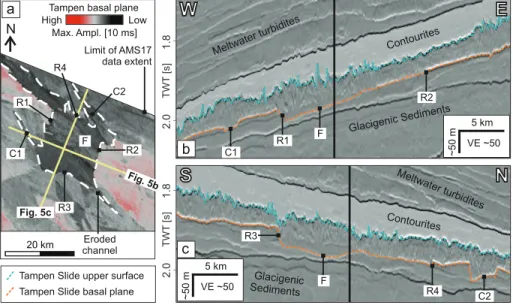
Figure 5. Eroded ramps, flats, and channels in the northern reaches of the study area. (a) Maximum amplitude surface within a 10 ms vertical window of the picked basal plane. See Figure 4 for location. (b, c) Seismic profiles crossing the eroded ramps, flats, and channels. Black line: profile crossing point; C1/C2: eroded channels; F: eroded flat section; R1/
R2/R3/R4: ramps; VE: Vertical Exaggeration. Data from AMS17 Vol. A, and courtesy of TGS.
Figure 6. Extensional ridges (spreading) along the upper headwall step and along the western sidewall of the Tampen Slide. (a) Maximum amplitude of the Tampen Slide's upper surface, and (b) seismic profile highlighting the character of the spreading ridges. Location of this figure is shown in Figure 3. VE: Vertical Exaggeration. Data from AMS17 Vol. B, and courtesy of TGS.
This slump has a volume of ∼12 km3 and its limit is delineated by an upward step in the basal glide plane (Figure 8).
The second subsequent failure, on the eastern side of the Tampen Slide's main headwall, has a cauliflower-shaped headwall (Figure 9).
Along-slope-orientated elongated ridges are present both at the headwall and within the toe region of this failure. The ridges within the headwall region are similar to those described in Section 4.2, along the upper step of the headwall and along the western sidewall. The ridges within the toe region of this comparatively small volume (∼36 km3) failure have a cha- otic interior and minimal topographic signature (Figure 9b).
4.5. Thinning of the Tampen Slide Over the Faroe-Shetland Escarpment
The deposits of the Tampen Slide thin toward the north-western corner of the data coverage, and most notably over the Faroe-Shetland Escarp- ment, the eastern boundary of the volcanic Møre Marginal High (Fig- ure 10). On the eastern side of this divide, the deposits are generally 40–50 m thick, but thin to <20 m on the western side.
5. Discussion
The high resolution and extensive coverage of these 3-D seismic data enable us to better constrain the character of the Tampen Slide. In this section, we discuss how the Tampen Slide morphology provides new in- sights into its emplacement. We then compare the morphology and em- placement mechanism of the Tampen Slide to that of other megaslides on passive margins, and conclude by outlining a new megaslide failure model and its implications for tsunami generation.
5.1. Emplacement of the Tampen Slide 5.1.1. The Main Failure
The smoothness of the basal plane (Figure 4a), the broad (>20 km wide), downslope-orientated stripes of varying maximum amplitude of the basal plane (Figure 4b), and the continuity of internal deformation across the slide deposits (e.g., Figures 2, 7, and 10) indicate that the mate- rial largely failed as one along a single stratigraphic horizon. Consequent- ly, we suggest that the initial failure began at the southern edge of the headwall (at the most upslope point of the basal plane), and propagated
∼290 km northwards along the eastern side of the headwall, remobilizing in excess of 720 km3 of sediments (the volume that remains within the extent of the surveyed area) (Figure 11b).
5.1.1.1. Longitudinal Chutes and Ridges Within the Slide Deposits Within the deposits of the Tampen Slide, we identify downslope-elongat- ed (longitudinal) chutes (Figure 7; Section 4.3). These are similar to lon- gitudinal chutes that have been documented in landslides at fjord-head deltas (e.g., Kitimat Arm in British Columbia; Prior et al., 1981) and in deposits of the Storegga Slide (Bugge et al., 1988), where they have been interpreted as regions of faster motion within the debris. Consequently, we suggest that varying flow speeds within the failed material resulted in the development of these longitudinal chutes within the Tampen Slide deposits.
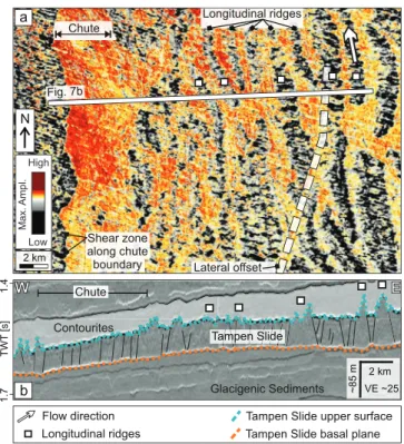
Figure 7. Longitudinal ridges and chutes within the Tampen Slide deposits. (a) Maximum amplitude of the Tampen Slide's upper surface and (b) seismic profile highlighting the character of the longitudinal ridges and chutes. Note the high level of internal deformation of the slide deposits here, within the central region of the headwall, compared to those along the western side of the headwall (Figure 5; from the same data volume).
Location of this figure is shown in Figure 3. VE: Vertical Exaggeration.
Data from AMS17 Vol. B, and courtesy of TGS.
Figure 8. Seismic profile crossing a small volume (∼12 km3), retrogressive slump on the western sidewall of the Tampen Slide. Note the blocky character of the slump deposits. Location of this figure is shown in Figure 3. VE: Vertical Exaggeration. Data from AMS17 Vol. B, and courtesy of TGS.
We also observe up to 40 m high, longitudinal ridges within the slide deposits (Figure 7; Section 4.3). The height of these ridges distinguishes them from flowlines or longitudinal lineations, which typically have min- imal relief (<1 m; Masson et al., 1993) and appear in pairs, marking the boundaries of longitudinal shear zones (Bull et al., 2009; Gee et al., 2005), unlike the features we document here. Furthermore, their downslope orientation also distinguishes these ridges from slump folds, which have similar geomorphology but are perpendicular to the direction of motion (Bull et al., 2009). While such large-scale longitudinal ridges are fre- quently present in terrestrial and volcanic landslide deposits (e.g., Du- fresne & Davies, 2009, and references therein), this is the first time, to our knowledge, that they have been observed in a deep marine environment.
Simple laboratory studies indicate that the formation of longitudinal ridges depends upon lateral segregation of grains at the front of the de- bris flow (Dufresne & Davies, 2009; Pouliquen et al., 1997). The grains are segregated according to size and shape, where the ridges are made up of coarser, more angular particles (e.g., sand grains), while fin- er-grained material (e.g., mud grains) fills the central channels (Valder- rama et al., 2017). While these studies are certainly simplified compared to the natural case, the authors (Dufresne & Davies, 2009; Pouliquen et al., 1997; Valderrama et al., 2017) found that their results were consist- ent with the character of debris avalanche deposits in several locations.
The development of longitudinal ridges also seems to require high ba- sal shear, which arises as a result of mechanical differences between the glide plane and the overlying material (Dufresne & Davies, 2009). In gla- cial environments, this is often attributed to the presence of an icy basal layer; however, based on wavelength analyses of ridges within a Martian landslide, Magnarini et al. (2019) suggested that longitudinal ridges are inevitable once a kinematic threshold within the rapidly failing mass is exceeded. Furthermore, longitudinal ridges seem more likely to develop in flows where the longitudinal velocity is much greater than the lateral velocity, such as in cases where the flow is laterally constrained (Dufresne
& Davies, 2009).
5.1.1.2. Diversion Around the Faroe-Shetland Escarpment
The deposits of the Tampen Slide thin across the Faroe-Shetland Es- carpment (Figure 10). This near-linear variation in thickness across the eastern margin of the Møre Marginal High leads us to suggest that the Møre Marginal High acted as a topographic constraint, which prevent- ed the Tampen Slide deposits from continuing their downslope run-out away from the continental margin. This resulted in a large volume of sediments remaining proximal to the headwall (Figure 11b), rather than being evacuated out of the headwall region, as is typical for megaslides on passive margins (Figure 11f; e.g., Hill et al., 2019; Kvalstad et al., 2005;
Li et al., 2017; Vanneste et al., 2006). Additionally, the lateral constraints and corresponding shift in the direction of transport of the failed mass may also have aided the development and preservation of the <40 m high longitudinal ridges identified within the slide deposits (Figure 7).
The erosional feature in the northern part of the headwall region (Fig- ure 5), including the two steps and the interlinking portion of the glide plane, is orientated roughly parallel to the failure direction (downslope), Figure 9. The ∼36 km3 retrogressive debris flow on the eastern headwall
of the Tampen Slide. (a) Maximum amplitude of the Tampen Slide's upper surface and (b) seismic profile highlighting the character of the compressional ridges at the toe of this failure. Location of this figure is shown in Figure 3. VE: Vertical Exaggeration. Amplitude data from AMS17 Vol. B, and seismic profile from AMS17 Vol. A. Data courtesy of TGS.
and bears striking similarity to features that have been described as ramps and flats (e.g., Bull et al., 2009;
Frey-Martínez et al., 2005; Omosanya & Alves, 2013; Trincardi & Argnani, 1990). Ramps and flats have been observed in many major slides, including the Møre Slide that is buried beneath the Tampen Slide (Bull et al., 2009; Evans et al., 1996), and have been suggested to occur where there are multiple, low shear strength layers or localized erosion during translation of the failed mass (Bull et al., 2009; Strachan, 2002).
We suggest that the slowing and/or redirection (pivoting) of the failed deposits in response to the topo- graphical boundary imposed by the Faroe-Shetland Escarpment could account for the location of these ramps and flats on the basal plane of the Tampen Slide.
5.1.2. Spreading Along the Western Sidewall and the Upper Headwall Step
The ridges observed along the western sidewall and the upper step of the headwall decrease in height and have a more chaotic interior with distance from the head- and sidewall (Figure 6). These characteristics are typical of ridges that have elsewhere been associated with spreading—a process thought to result from seis- mic loading and loss of basal support (Lastras et al., 2003; Micallef et al., 2007). Hjelstuen and Grinde (2016) identified spreading ridges in a small area on the upper step of the Tampen Slide's headwall (∼270 km2; Fig- ure 3a). The lateral extent of our data enables us to map spreading across ∼860 km2 of the upper headwall step (Figure 3c).
We suggest that this spreading, both along the upper step of the headwall and along the western side- wall, occurred in response to loss of support following the first phase of failure. The spreading along the base of the western sidewall (incorporating ∼125 km3 of sediment) began in the south where the basal plane dips toward the north (Figure 4), and extended northwards along the sidewall (Figure 11c).
This corresponds with the region that is characterized by very high basal plane amplitudes along the western sidewall (Figure 4b), and we interpret that this variation in amplitude of the basal plane marks the lateral boundary between the sediments that failed as part of the main failure, and those associated with subsequent spreading. This was followed by spreading along the top step of the head- and sidewall (Figures 3, 6, and 11d).
5.1.3. Retrogressive Failures of the Tampen Slide Headwall
The blocky nature of the ∼12 km3 slump on the western sidewall (Figure 8), as well as its clearly defined limit, which is demarcated by an upward step on the basal glide plane, lead us to interpret it as a retro- Figure 10. The deposits of the Tampen Slide thin over the Faroe-Shetland Escarpment (FSE). (a) Seismic profile crossing the FSE and (b) thickness map highlighting the distribution of the Tampen Slide deposits within the Tampen Slide headwall region. The deposits are at their thickest along the western sidewall, where they are characterized by ridges and troughs characteristic of spreading (Figure 5), and thinnest west of the FSE. White line shows the location of the seismic profile in (a); VE: Vertical Exaggeration. Seismic profile from AMS17 Vol. A. Data courtesy of TGS.
gressive slump that was emplaced following the main Tampen Slide (Figure 11d). The cauliflower shape of the headwall of the debris flow on the eastern side of the Tampen Slide's headwall (Figures 9 and 11d), similarly, has previously been linked to retrogressive landslide development (Micallef et al., 2008). The ridges at the headwall and toe of this debris flow are consistent with ridges that result from extensional spreading and compression within the confined toe of a landslide, respectively (Bull et al., 2009). The timing of this slump and debris flow, as well as that of the spreading along the upper step of the head- wall, is poorly constrained, and could have occurred minutes, hours, or even many years after the main Tampen Slide event.
5.2. Comparison to Other Passive Margin Megaslides 5.2.1. Retrogressive Development
Most megaslides worldwide are thought to have developed retrogressively, with numerous failures across multiple headwalls and glide planes typically accounting for their total volume (e.g., Antobreh & Kras- tel, 2007; Georgiopoulou et al., 2010; Hill et al., 2019; Kvalstad et al., 2005; Laberg & Vorren, 2000; Vanneste et al., 2006). It is clear that some relatively small retrogressive failures occurred at the Tampen Slide head- wall following the first phase of failure (Figures 8, 9, and 11a–11d). However, the Tampen Slide deviates from other megaslides on passive margins (Figures 11e–11h) in that initial failure of the Tampen Slide Figure 11. Conceptual models showing (a–d) development of a megaslide along a single glide plane (as for the Tampen Slide) and (e–h) upslope-migrating failure across multiple glide planes (responsible for the large total volume of other passive margin megaslides, such as the Storegga, Trænadjupet, Hinlopen/Yermak, Sahara, and Cape Fear Slides).
seems to have involved a prodigious volume of sediments (>720 km3) that were translated as one mass along a single glide plane, accounting for the majority of the total failed volume. This interpretation is in agreement with previous studies of the Tampen Slide (Bellwald et al., 2019; Gafeira et al., 2010; Hjelstuen
& Grinde, 2016; Nygård et al., 2005). In comparison, the neighboring Storegga Slide has been suggested to have failed in tens of (more than 70) phases (Haflidason et al., 2004; Micallef et al., 2009). This difference is significant because these slides both occurred on the same margin, within the same type of sediments (glacigenic), along the same type of glide plane (a glacimarine layer), and were supposedly both triggered by a large earthquake (Bellwald et al., 2019; Kvalstad et al., 2005). Consequently, we could reasonably expect them to fail in a similar way. In the next section, we consider possible causes for the difference in failure mechanism.
5.2.2. Preconditioning and Triggering Factors
Similarly to other submarine megaslides, which seem to have developed on slopes with very low gradi- ents (<2o; e.g., Hampton et al., 1996; Hühnerbach et al., 2004; Urlaub et al., 2015), the Tampen Slide's basal plane also dips very shallowly (<1° on average). Bellwald et al. (2019) used 2-D Finite Element modeling and geotechnical data from the nearby Ormen Lange gas field to evaluate the effects of various preconditioning factors for the Tampen Slide. Their results indicated that a basal glacimarine sediment layer was critical for the generation of sediment overpressure. Moreover, Bellwald et al. (2019) found that overpressure alone was not enough to trigger the Tampen Slide, and an earthquake of >M6.9, proximal to the headwall, was required for failure to occur (Figure 11a). While seismicity in the region is generally low to moderate, an earthquake of Mw5.4 occurred in 1988, in an area where no active postglacial faults have been mapped in the distal region of the North Sea Trough Mouth Fan (Norwegian National Seismic Network, www.skjelv.no; Bellwald et al., 2019). Larger earthquakes of Mw6.5–7 are thought to result from isostatic rebound offshore Norway, following the onset of an interglacial period (Bellwald et al., 2019;
Bungum et al., 2005). No evidence of gas hydrate dissociation has been found within the sediments re- lated to the Tampen Slide (both failed and unfailed, and within the seismic data presented in this study, as well as in the work of Nygård et al., 2005; Bellwald et al., 2019). The Storegga Slide, in comparison, is thought to have also been preconditioned by high excess pore pressure combined with earthquake loading, but its triggering earthquake seems to have occurred on the lower continental slope (Figure 11e;
Haflidason et al., 2004; Kvalstad et al., 2005). Failure of the Storegga Slide, then, initiated on the lower continental slope and migrated upslope, incorporating multiple glide planes and escarpments (Haflida- son et al., 2004; Micallef et al., 2009). Thus, when a landslide is triggered by an earthquake, the location of that earthquake may be a key factor that influences whether a landslide develops retrogressively or along a single glide plane.
Furthermore, the location and number of glacimarine weak layers, as well as rapid sedimentation, may also play an important role in controlling whether a landslide fails retrogressively or mainly during a single phase. The Tampen Slide is located within the proximal deposits of the North Sea Fan, a region with highly variable sedimentation rates. In glacial periods, the presence of ice on the shelf can result in as much as a 10-fold increase in hemipelagic sedimentation (Lekens et al., 2009), with extreme sedi- mentation rates exceeding 20 m/Kyr (or even 100 m/Kyr during the last glaciation; Bellwald et al., 2020) on the upper slope directly affected by ice-stream sediment delivery (Hjelstuen et al., 2004). Nygård et al. (2007) found that the Norwegian Channel ice stream loaded the North Sea Fan with as much as 1.1 Gt of sediment per year during the last glacial stage. In contrast, sedimentation at the neighboring Storegga Slide is locally controlled by the same type of glacigenic sediments, and occurs at a much slower rate, averaging 1 m/Kyr over the last 250 Kyr (Hjelstuen et al., 2004). Weak layers, which may be prone to failure, are then more condensed within the Storegga Slide region. This may favor the develop- ment of retrogressive sliding in the Storegga region. In contrast, within the North Sea Fan, weak layers are typically separated by a thicker sedimentary unit, which may favor the development of a megaslide along a single plane as observed at the Tampen Slide. The relative importance of these features—the location, number, and spacing of glacimarine weak layers, as well as the magnitude and attenuation of a triggering earthquake—should, however, be validated through careful numerical modeling in the future.
5.3. Wider Implications for Hazards and Tsunami Generation
The failure mechanism and landslide geometry have major implications for the potential consequences (es- pecially tsunami generation potential) resulting from a submarine landslide. To date, no tsunami deposits have been linked to the Tampen Slide. However, the Tampen Slide is thought to have occurred during MIS 6, ca. 130 ka (Nygård et al., 2005), and the subsequent retreat and growth of the Fennoscandian ice sheet, as evidenced by iceberg plow marks within the sedimentary layers (e.g., Bellwald et al., 2020; Montelli et al., 2018), may have led to erosion of any tsunami deposits related to the Tampen Slide. Furthermore, lower sea level at that time may also contribute to a lack of tsunami deposits related to the Tampen Slide. It should be noted that, while landslide volume is an important parameter for generating a tsunami, not all large subma- rine landslides result in tsunamis. For example, the retrogressive Trænadjupet Slide, also located offshore Norway, occurred ca. 4,500 years ago and involved a total volume of 500–1,000 km3, but does not seem to have resulted in a tsunami (Laberg & Vorren, 2000; Løvholt et al., 2017). Using a coupled landslide-tsunami model, Løvholt et al. (2017) found that this was likely a result of low failure velocity (supported by observa- tions of blocky deposits near the headwall and limited turbidity current deposits), with lesser volume and a greater distance to the coastline (compared to the Storegga Slide) also playing a role. Contrastingly, at the Tampen Slide, although a large volume of sediment remains proximal to the headwall, the interior of the slide deposits is heavily deformed (e.g., Figures 5 and 7). This, together with the height of the main headwall (∼150 m), suggests the rapid displacement of a prodigious (>720 km3) sediment volume. The initial accel- eration of the failed mass, however, cannot be reconstructed using the seismic data. This, together with the absence of tsunami deposits linked to the Tampen Slide, makes it impossible to construct a well-constrained tsunami model. However, such a failure may generate a far larger tsunami than a multiphase, retrogressive megaslide with a similar total volume (e.g., the Storegga Slide), and should be considered in future hazard analysis.
6. Conclusions
In this study, we present laterally extensive, high-resolution processed 3-D seismic data from the headwall of the buried Tampen Slide offshore Norway. These data reveal the character of the slide deposits at a high level of detail and allow us to better understand their emplacement.
Unlike other megaslides on passive continental margins, the deposits of which are typically evacuated away from the headwall, a large volume of the Tampen Slide deposits remain close to the headwall. We suggest that this is because the Tampen Slide deposits were laterally constrained by the kilometer-high Faroe-Shet- land Escarpment, over which the slide deposits thin markedly. This lateral constraint significantly impacted the slide flow dynamics, resulting in the development of erosional ramps and flats in the northern part of the surveyed area as the flow redirected northwards in response to the topographical constraint imposed by the Faroe-Shetland Escarpment.
We identify regions of spreading, confined toe-compression, and translation within the deposits of the Tampen Slide. Within the translational deposits, there are longitudinal (downslope-elongated) chutes sim- ilar to those identified at the neighboring Storegga Slide, which have been interpreted as regions of faster downslope motion within the slide deposits. We also identify longitudinal ridges within the translational body of the Tampen Slide. Such ridges have previously been suggested to be an intrinsic characteristic of landslides once they exceed certain kinematic parameters, but this is the first time, to our knowledge, that they have been imaged within deep water landslide deposits. We suggest that the preservation of these ridg- es in the Tampen Slide deposits is a consequence of the landslide deposits remaining within the headwall region.
Apart from a few erosional features, the Tampen Slide's basal glide plane is relatively smooth. This, com- bined with the continuity of internal deformation across the slide deposits, indicates that the majority of the slide deposits failed in a single phase as one mass. This single phase failure differs markedly from other megaslides on passive margins, whose tiered glide planes and multiple headwalls are thought to show retro- gressive (upslope-migrating) failure behavior. This variation, where a single failure, rather than several tens of failures, accounts for most of the total slide volume, may have a large impact on the tsunami generation
potential of the megaslide. While the Tampen Slide is the first submarine megaslide shown to have failed in this way, other (potentially as yet undiscovered) megaslides may fail in a similar way. Consequently, the failure mechanism should be considered carefully when assessing the hazard potential of submarine megaslides.
Data Availability Statement
The 3-D multiclient seismic data (AMS17) used in this study is courtesy of TGS. These data are part of the Atlantic Margins multiyear program, which covered more than 50,000 km2 between 2017 and 2019. Access to the data can be gained through purchasing a license from TGS.
References
Antobreh, A. A., & Krastel, S. (2007). Mauritania Slide Complex: Morphology, seismic characterisation and processes of formation. Inter- national Journal of Earth Sciences, 96(3), 451–472. https://doi.org/10.1007/s00531-006-0112-8
Bellwald, B., Planke, S., Becker, L. W. M., & Myklebust, R. (2020). Meltwater sediment transport as the dominating process in mid-latitude trough mouth fan formation. Nature Communications, 11(1), 1–10. https://doi.org/10.1038/s41467-020-18337-4
Bellwald, B., Urlaub, M., Hjelstuen, B. O., Sejrup, H. P., Sørensen, M. B., Forsberg, C. F., & Vanneste, M. (2019). NE Atlantic conti- nental slope stability from a numerical modeling perspective. Quaternary Science Reviews, 203, 248–265. https://doi.org/10.1016/j.
quascirev.2018.11.019
Bondevik, S., Løvholt, F., Harbitz, C. B., Mangerud, J., Dawson, A., & Svendsen, J. I. (2005). The Storegga Slide tsunami – Comparing field ob- servations with numerical simulations. Marine and Petroleum Geology, 22, 195–208. https://doi.org/10.1016/B978-0-08-044694-3.50021-4 Bryn, P., Berg, K., Forsberg, C. F., Solheim, A., & Kvalstad, T. J. (2005). Explaining the Storegga Slide. Marine and Petroleum Geology,
22(1–2), 11–19. https://doi.org/10.1016/j.marpetgeo.2004.12.003
Bugge, T., Belderson, R. H., & Kenyon, N. H. (1988). The Storegga Slide. Royal Society of London Philosophical Transactions, 325A, 357–388.
https://doi.org/10.1098/rsta.1988.0055
Bull, S., Cartwright, J., & Huuse, M. (2009). A review of kinematic indicators from mass-transport complexes using 3D seismic data. Ma- rine and Petroleum Geology, 26(7), 1132–1151. https://doi.org/10.1016/j.marpetgeo.2008.09.011
Bungum, H., Lindholm, C., & Faleide, J. I. (2005). Postglacial seismicity offshore mid-Norway with emphasis on spatio-temporal-magnitu- dal variations. Marine and Petroleum Geology, 22(1–2), 137–148. https://doi.org/10.1016/j.marpetgeo.2004.10.007
Dufresne, A., & Davies, T. R. (2009). Longitudinal ridges in mass movement deposits. Geomorphology, 105, 171–181. https://doi.
org/10.1016/j.geomorph.2008.09.009
Evans, D., King, E. L., Kenyon, N. H., Brett, C., & Wallis, D. (1996). Evidence for long-term instability in the Storegga Slide region off west- ern Norway. Marine Geology, 130(3–4), 281–292. https://doi.org/10.1016/0025-3227(95)00135-2
Frey-Martínez, J., Cartwright, J., & Hall, B. (2005). 3D seismic interpretation of slump complexes: Examples from the continental margin of Israel. Basin Research, 17(1), 83–108. https://doi.org/10.1111/j.1365-2117.2005.00255.x
Gafeira, J., Long, D., Scrutton, R., & Evans, D. (2010). 3D seismic evidence of internal structure within Tampen Slide deposits on the North Sea Fan: Are chaotic deposits that chaotic? Journal of the Geological Society, 167, 605–616. https://doi.org/10.1144/0016-76492009-047 Gee, M. J. R., Gawthorpe, R. L., & Friedmann, J. S. (2005). Giant striations at the base of a submarine landslide. Marine Geology, 214(1–3),
287–294. https://doi.org/10.1016/j.margeo.2004.09.003
Georgiopoulou, A., Masson, D. G., Wynn, R. B., & Krastel, S. (2010). Sahara slide: Age, initiation, and processes of a giant submarine slide.
Geochemistry, Geophysics, Geosystems, 11, Q07014. https://doi.org/10.1029/2010GC003066
Haflidason, H., Lien, R., Sejrup, H. P., Forsberg, C. F., & Bryn, P. (2005). The dating and morphometry of the Storegga Slide. Marine and Petroleum Geology, 22, 123–136. https://doi.org/10.1016/j.marpetgeo.2004.10.008
Haflidason, H., Sejrup, H. P., Nygård, A., Mienert, J., Bryn, P., Lien, R., et al. (2004). The Storegga Slide: Architecture, geometry and slide development. Marine Geology, 213(1–4), 201–234. https://doi.org/10.1016/j.margeo.2004.10.007
Hampton, M. A., Lee, H. J., & Locat, J. (1996). Submarine landslides. Reviews of Geophysics, 34(1), 33–50. https://doi.org/10.1029/95RG03287 Harbitz, C. B., Løvholt, F., & Bungum, H. (2014). Submarine landslide tsunamis: How extreme and how likely? Natural Hazards, 72,
1341–1374. https://doi.org/10.1007/s11069-013-0681-3
Hill, J. C., Brothers, D. S., Hornbach, M. J., Sawyer, D. E., Shillington, D. J., & Bécel, A. (2019). Subsurface controls on the development of the Cape Fear Slide Complex, central US Atlantic Margin. In G. Lintern, D. Mosher, L. Moscardelli, P. T. Bobrowsky, C. Campbell, J.
Chaytor, et al. (Eds.), Submarine mass movements and their consequences. 477th ed. (pp. 169–181). London, UK: Geological Society of London Special Publications. https://doi.org/10.1144/SP477.17
Hjelstuen, B. O., & Grinde, S. (2016). 3D seismic investigations of pleistocene mass transport deposits and glacigenic debris flows on the North Sea Fan, NE Atlantic Margin. In G. Lamarche, J. Mountjoy, S. Bull, T. Hubble, S. Krastel, E. Lane, et al. (Eds.), Submarine mass movements and their consequences, advances in natural and technological hazards research. 41st ed. (pp. 265–272). Switzerland: Springer International. https://doi.org/10.1007/978-3-319-20979-1_26
Hjelstuen, B. O., Sejrup, H. P., Haflidason, H., Nygård, A., Berstad, I. M., & Knorr, G. (2004). Late Quaternary seismic stratigraphy and geological development of the south Vøring margin, Norwegian Sea. Quaternary Science Reviews, 23(16–17), 1847–1865. https://doi.
org/10.1016/j.quascirev.2004.03.005
Hühnerbach, V., & Masson, D. G. (2004). Landslides in the North Atlantic and its adjacent seas: An analysis of their morphology, setting and behaviour. Marine Geology, 213(1–4), 343–362. https://doi.org/10.1016/j.margeo.2004.10.013
King, E. L., Sejrup, H. P., Haflidason, H., Elverhøi, A., & Aarseth, I. (1996). Quaternary seismic stratigraphy of the North Sea Fan: Gla- cially-fed gravity flow aprons, hemipelagic sediments, and large submarine slides. Marine Geology, 130(3–4), 293–315. https://doi.
org/10.1016/0025-3227(95)00168-9
Kiørboe, L. (1999). Stratigraphic relationships of the Lower Tertiary of the Faeroe basalt Plateau and the Faeroe–Shetland basin. Petroleum Geology Conference Series, pp. 559–571. https://doi.org/10.1144/0050559
Acknowledgments
We are grateful to Derek Sawyer and an anonymous reviewer, as well as the associate editor (Brandon Dugan), and the editor (Isabelle Manighetti), for their constructive feedback that greatly improved this manuscript. R. S. Barrett is funded by the European Union's Horizon 2020 research and innovation programme under the Marie Skłodows- ka-Curie Actions grant agreement No.
721403. A. Micallef is funded by the European Research Council (ERC) under the European Union's Horizon 2020 Programme grant agreement No. 677898. S. Planke acknowledges support from the Norwegian Research Council through Centre of Excellence funding to CEED (project no. 223272).
Open access funding enabled and organized by Projekt DEAL.
Korup, O., Clague, J. J., Hermanns, R. L., Hewitt, K., Strom, A. L., & Weidinger, J. T. (2007). Giant landslides, topography, and erosion. Earth and Planetary Science Letters, 261(3–4), 578–589. https://doi.org/10.1016/j.epsl.2007.07.025
Kvalstad, T. J., Andresen, L., Forsberg, C. F., Berg, K., Bryn, P., & Wangen, M. (2005). The Storegga slide: Evaluation of triggering sources and slide mechanics. Marine and Petroleum Geology, 22(1–2), 245–256. https://doi.org/10.1016/j.marpetgeo.2004.10.019
Laberg, J. S., & Vorren, T. O. (2000). The Trænadjupet Slide, offshore Norway – Morphology, evacuation and triggering mechanisms. Ma- rine Geology, 171(1–4), 95–114. https://doi.org/10.1016/S0025-3227(00)00112-2
Lastras, G., Canals, M., & Urgeles, R. (2003). Lessons from sea-floor and subsea-floor imagery of the BIG'95 debris flow scar and deposit.
In J. Locat & J. Mienert (Eds.), Submarine mass movements and their consequences (pp. 425–431). Dordrecht, Netherlands: Kluwer Academic.
Lekens, W. A. H., Haflidason, H., Sejrup, H. P., Nygard, A., Richter, T., Vogt, C., & Frederichs, T. (2009). Sedimentation history of the northern North Sea Margin during the last 150 ka. Quaternary Science Reviews, 28(5–6), 469–483. https://doi.org/10.1016/j.quascirev.2008.11.010 Li, W., Alves, T. M., Urlaub, M., Georgiopoulou, A., Klaucke, I., Wynn, R. B., et al. (2017). Morphology, age and sediment dynamics of
the upper headwall of the Sahara Slide Complex, Northwest Africa: Evidence for a large Late Holocene failure. Marine Geology, 393, 109–123. https://doi.org/10.1016/j.margeo.2016.11.013
Lintern, D. G., Mosher, D. C., Moscardelli, L. G., Bobrowsky, P. T., Campbell, C., Chaytor, J. D., et al. (2018). Subaqueous Mass Movements and Their Consequences: Assessing Geohazards, Environmental Implications and Economic Significance of Subaqueous Landslides (477th ed.). London: Geological Society of London Special Publications. https://doi.org/10.1144/SP477
Løvholt, F., Bondevik, S., Laberg, J. S., Kim, J., & Boylan, N. (2017). Some giant submarine landslides do not produce large tsunamis. Geo- physical Research Letters, 44(16), 8463–8472. https://doi.org/10.1002/2017GL074062
Magnarini, G., Mitchell, T. M., Grindrod, P. M., & Schmitt, H. H. (2019). Granular flow mechanisms in Martian landslides. Nature Com- munications, 10, 4711. https://doi.org/10.1038/s41467-019-12734-0
Masson, D. G., Hugget, Q. J., & Brunsden, D. (1993). The surface texture of the Saharan debris flow deposit and some speculation on sub- marine debris flow processes. Sedimentology, 40, 583–598. https://doi.org/10.1111/j.1365-3091.1993.tb01351.x
Masson, D. G., Wynn, R. B., & Talling, P. J. (2010). Large landslides on passive continental margins: Processes, hypotheses and outstanding questions. In D. C. Mosher, L. Moscardelli, R. C. Shipp, J. D. Chaytor, C. D. P. Baxter, H. J. Lee, & R. Urgeles (Eds.), Submarine mass movements and their consequences: Advances in natural and technological hazards research (Vol. 28, pp. 153–165). Springer Science + Business Media. https://doi.org/10.1007/978-90-481-3071-9_13
Micallef, A., Berndt, C., Masson, D. G., & Stow, D. A. V. (2008). Scale invariant characteristics of the Storegga Slide and implications for large-scale submarine mass movements. Marine Geology, 247(1–2), 46–60. https://doi.org/10.1016/j.margeo.2007.08.003
Micallef, A., Masson, D. G., Berndt, C., & Stow, D. A. V. (2007). Morphology and mechanics of submarine spreading: A case study from the Storegga Slide. Journal of Geophysical Research, 112(3), 1–21. https://doi.org/10.1029/2006JF000739
Micallef, A., Masson, D. G., Berndt, C., & Stow, D. A. V. (2009). Development and mass movement processes of the north-eastern Storegga Slide. Quaternary Science Reviews, 28(5–6), 433–448. https://doi.org/10.1016/j.quascirev.2008.09.026
Montelli, A., Dowdeswell, J. A., Ottesen, D., & Johansen, S. E. (2018). 3D seismic evidence of buried iceberg ploughmarks from the mid-Norwegian continental margin reveals largely persistent North Atlantic Current through the Quaternary. Marine Geology, 399, 66–83. https://doi.org/10.1016/j.margeo.2017.11.016
Nygård, A., Sejrup, H. P., Haflidason, H., & Bryn, P. (2005). The glacial North Sea Fan, southern Norwegian Margin: Architecture and evo- lution from the upper continental slope to the deep-sea basin. Marine and Petroleum Geology, 22(1–2), 71–84. https://doi.org/10.1016/j.
marpetgeo.2004.12.001
Nygård, A., Sejrup, H. P., Haflidason, H., Lekens, W. A. H., Clark, C. D., & Bigg, G. R. (2007). Extreme sediment and ice discharge from marine-based ice streams: New evidence from the North Sea. Geology, 35(5), 395–398. https://doi.org/10.1130/G23364A.1
Omosanya, K. O., & Alves, T. M. (2013). Ramps and flats of mass-transport deposits (MTDs) as markers of seafloor strain on the flanks of rising diapirs (Espirito Santo Basin, SE Brasil). Marine Geology, 340, 82–97. https://doi.org/10.1016/j.margeo.2013.04.013
Pope, E. L., Talling, P. J., & Ó Cofaigh, C. (2018). The relationship between ice sheets and submarine mass movements in the Nordic Seas during the Quaternary. Earth-Science Reviews, 178, 208–256. https://doi.org/10.1016/j.earscirev.2018.01.007
Pouliquen, O., Delour, J., & Savage, S. B. (1997). Fingering in granular flows. Nature, 386(6627), 816–817.
Prior, D. B., Wiseman, W. J. J., & Bryant, W. R. (1981). Submarine chutes on the slopes of fjord deltas. Nature, 290, 326–328. https://doi.
org/10.1038/290326a0
Smith, W. H. F., & Wessel, P. (1990). Gridding with continuous curvature splines in tension. Geophysics, 55, 293–305.
Strachan, L. J. (2002). From geometry to genesis: A comparative field study of slump deposits and their modes of formation (PhD thesis).
University of Cardiff.
Trincardi, F., & Argnani, A. (1990). Gela submarine slide: A major basin-wide event in the plio-quaternary foredeep of Sicily. Geo-Marine Letters, 10(1), 13–21. https://doi.org/10.1007/BF02431017
Urlaub, M., Talling, P. J., Zervos, A., & Masson, D. G. (2015). What causes large submarine landslides on low gradient sediment accumula- tion? Journal of Geophysical Research: Solid Earth, 120, 1–18. https://doi.org/10.1002/2015JB012347
Valderrama, P., Roche, O., Samaniego, P., van Wyk des Fries, B., & Araujo, G. (2017). Granular fingering as a mechanism for ridge for- mation in debris avalanche deposits: Laboratory experiments and implications for Tutupaca volcano, Peru. Journal of Volcanology and Geothermal Research, 349, 409–418. https://doi.org/10.1016/j.jvolgeores.2017.12.004
Vanneste, M., Mienert, J., & Bünz, S. (2006). The Hinlopen Slide: A giant, submarine slope failure on the northern Svalbard margin, Arctic Ocean. Earth and Planetary Science Letters, 245(1–2), 373–388. https://doi.org/10.1016/j.epsl.2006.02.045
Watts, M., Talling, P., Hunt, J., Xuan, C., & van Peer, T. (2016). A new date for a large pre-Holocene Storegga Slide. EGU General Assembly Conference Abstracts. https://doi.org/10.13140/RG.2.2.36690.35527
Whiteside, W., Wang, B., Bondeson, H., & Li, Z. (2013). 3D imaging from 2D seismic data, an enhanced methodology. SEG Technical Pro- gram Expanded Abstracts https://doi.org/10.1190/segam2013-1148.1
Zastrozhnov, D., Gernigon, L., Gogin, I., Planke, S., Abdelmalak, M. M., Polteau, S., et al. (2020). Regional structure and polyphased Cretaceous-Paleocene rift and basin development of the mid-Norwegian volcanic passive margin. Marine and Petroleum Geology, 115, 104269. https://doi.org/10.1016/j.marpetgeo.2020.104269