GraX : Graph Exchange Format
J ¨urgen Ebert Bernt Kullbach Andreas Winter
University of Koblenz-Landau Institute for Software Technology Rheinau 1, D-56075 Koblenz, Germany
✆++49 262 287-2722|2704|2764 (ebert|kullbach|winter)@uni-koblenz.de
Abstract
This paper introduces the GraX graph exchange format that can be used by software engineering tools. The data to be transferred are separated into a schema and an instance part which are both exchanged in the same way. The application ofGraX as a vehicle for tool interoperability will be exemplified in the context of CASE and software reengineering tools.
Keywords: exchange format, XML, CASE tool interoperability, reengineering tool interoperability, graph technology
1 Motivation
To enable interoperability between tools supporting various tasks in software engineering a suitable mechanism for interchanging data between those tools is required. Several data exchange formats have been developed to exchange models of software systems and information systems on various levels of abstraction (for CASE1 tools see e. g. CDIF [7, 8] and XMI [11] and for CARE1 tools see e. g. ASFIX [12], RSF [16], and TA [9]).
Due to the heterogeneity of the subject domain of different tools there is evidence that data to be in- terchanged can not be mapped to a general metaschema [8]. As a consequence a common interchange format enabling tool interoperability in software engineering has to support the exchange of instance data and schema data [3].
Here, the GraX (graph exchange) format [3] is proposed as an interchange format, which allows ex- changing instance and schema data in the same way. GraX is formally based onTGraphs[1, 6] which define a very general class of graphs. As notationGraX uses the markup language XML [13].
This paper is organized as follows: Section 2 introduces the GraX exchange format for representing graphs on the instance level as well as on the schema level. In section 3 the application ofGraX in tool interoperability is sketched. The paper ends with a conclusion in section 4.
2 GraX
Data representations in CASE and CARE tools are usually based on data structures like relations, syntax trees or graphs. To enable data interchange between tools a common data format has to be chosen. This either has to enclose all of the these data structures or it else has to allow an easy mapping between them. A common kind of data structure which can be matched to all of the above structures is given byTGraphs. TGraphs are directed graphs, whose vertices and edges are typed and attributed. Within TGraphsedges are viewed as first class entities. While being treated independently from vertices, edges can be traversed along and against their direction. To express sequences of edges or vertices TGraphs
1CASE = computer-aided software engineering; CARE = computer-aided reengineering
are additionally ordered. Furthermore, TGraphsare scalable with respect to the application context in the sense, that not all properties ofTGraphshave to be used to their full extent.
Since TGraphs are a purely structural means for modeling, their meaning depends on the application context in which they are exchanged. This context determines which vertex and edge types, which at- tributes and which incidence relations are modeled. Conceptual modeling techniques using extended entity-relationship diagrams or class diagrams are used to define classes ofTGraphs representing this application-related knowledge. Here, entity types and relationship types are used to specify vertex types and edge types together with their attribute and incidence structures. Multiple generalization is allowed for vertex and edge types. Further structural information can be modeled by using aggregation. Ad- ditional constraints, e. g. degree constraints or restrictions to relational graphs or dags are specified by graphical annotations or by textual constraints. To describe the schema part of the data to be inter- changed, we propose theEER/GRAL-approach to graph-based, conceptual modeling [6], which is suited toTGraphs.
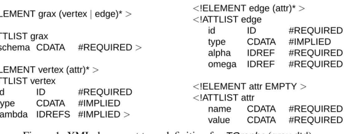
So, the instance data structures supported by theGraX interchange format areTGraphsand the accord- ing schematic information is given byEER/GRALconceptual models. Thus, in a concrete notation the underlying conceptual model, the vertices and edges including their type and attribute information, the incidence relationships and the ordering of vertices and edges have to be described. Figure 1 shows the XML document type definition (DTD) supplying such a notation. This DTD reflects the formal specifi- cation ofTGraphsas defined in [1].
<!ELEMENT grax (vertex|edge)*>
<!ATTLIST grax
schema CDATA #REQUIRED>
<!ELEMENT vertex (attr)*>
<!ATTLIST vertex
id ID #REQUIRED
type CDATA #IMPLIED lambda IDREFS #IMPLIED>
<!ELEMENT edge (attr)*>
<!ATTLIST edge
id ID #REQUIRED
type CDATA #IMPLIED alpha IDREF #REQUIRED omega IDREF #REQUIRED>
<!ELEMENT attr EMPTY>
<!ATTLIST attr
name CDATA #REQUIRED value CDATA #REQUIRED>
Figure 1: XML document type definition forTGraphs(grax.dtd)
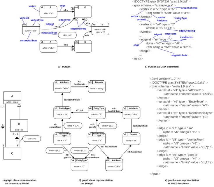
Figure 2a shows a small graph with vertices of types A, B, and C and edges of type r and s. The numbers associated to the edges model the ordering of these edges with regards to their incident ver- tices. This graph is represented by the associated GraX document in figure 2b. The first lines of this XML document refer to the underlying XML version and to the GraX DTD. This intitial information is followed by the graph definition enclosed by <grax> and </grax> tags. Within the <grax> tag a reference to the graph schema (example.scx) is specified. Vertices and edges are represented asvertex andedgeelements, respectively, which include key and type identifiers as XML attributes. Vertex and edge attributes are given by associating identifiers and values throughattr-elements. The global ordering of vertices and edges is given by their textual position. The local ordering of edges with respect to a vertex is specified by edge sequences in thelambda-attribute of vertices within the correspondingvertex tag. Finally, incidences including the orientation of edges are described byalpha andomegaattributes ofedgeelements.
The schema information of graphs like the one in figure 2a is specified in figure 2c. In the entity rela- tionship (EER) diagram vertex typesA, B, andC and edge typesr ands including their attribute and incidence structure are defined.
SinceEER-diagrams likewise are structured information they may also be represented asTGraphs. The metaschema describing the graph structure of those EER-TGraphs is introduced in [3]. This meta-
A v1
aAttr = "a"
B v6
aAttr = "bbb"
bAttr = 27
A v3
aAttr = "abc"
C v4
C v5 A
v2 aAttr = "abc"
e1:s
e2:s
e3:s
e5:s
e4:r rAttr = 42
1 2 3
1
vertex edge
edgeId
edgeType vertexId
vertexType
vertexAttribute
edgeAttribute
edgeOrdering
a) TGraph b) TGraph as GraX document
<?xml version=”1.0” ?>
<!DOCTYPE grax SYSTEM ”grax.1.0.dtd”>
<grax schema = ”example.scx”>
<vertex id = ”v1” type = ”A”>
<attr name = ”aAttr” value = ”a”/>
</vertex>
. . .
<vertex id = ”v4” type = ”C”
lambda = ”e5 e2 e1”>
</vertex>
. . .
<edge id = ”e4” type = ”r”
alpha = ”v5” omega = ”v6”>
<attr name = ”rAttr” value = ”42” />
</edge>
. . .
</grax>
vertex
edge
vertexId vertexType
edgeId edgeType vertex Attribute
edgeAttribute incidences
GraphSchema
edgeOrdering
EntityType v2
name = "A"
Attribute v1
name = "aAttr"
Domain v5
name = "string"
EntityType v6
name = "B"
v3 name = "s"
Relationship
Type v7
name = "r"
Relationship Type
EntityType v4
name = "C"
Attribute v8
name = "bAttr"
Attribute v10
name = "rAttr"
Domain v9
name = "int"
e1: hasAttribute e2:
hasDomain
e3: hasDomain
e4: hasDomain e5 :
hasAttribute
e6: hasAttribute e7: isA
e8:
comesFrom
e9:
goesTo
e10:
goesTo
e11:
comesFrom
limits = (1,*) limits = (0,1)
limits = (1,1) limits = (1,1)
<?xml version=”1.0” ?>
<!DOCTYPE grax SYSTEM ”grax.1.0.dtd”>
<grax schema = ”meta.1.0.scx”>
<vertex id = ”v1” type = ”Attribute”>
<attr name = ”name” value = ”aAttr”/>
</vertex>
<vertex id = ”v2” type = ”EntityType”>
<attr name = ”name” value = ”A”/>
</vertex>
<vertex id = ”v3” type = ”RelationshipType”>
<attr name = ”name” value = ”s”/>
</vertex>
. . .
<edge id = ”e7” type = ”isA”
alpha = ”v6” omega = ”v2”>
</edge>
<edge id = ”e8” type = ”comesFrom”
alpha = ”v3” omega = ”v2”>
<attr name = ”limits” value = ”(1,*)” />
</edge>
<edge id = ”e9” type = ”goesTo”
alpha = ”v3” omega = ”v4”>
<attr name = ”limits” value = ”(1,1)” />
</edge>
. . .
</grax>
c) graph class representation as conceptual Model
d) graph class representation as TGraph
e) graph class representation as GraX document bAttr : int
B
C s
r rAttr : int
1 .. *
1 1
0 .. 1 aAttr : string
A
Figure 2:GraX example: instance and schema information
schema is another conceptual model that specifies entity types, relationship types, attributes and domains and associations between them on the meta level. TheTGraph in figure 2d matches the metaschema specification and is equivalent to the conceptual model in figure 2c. So both schema and instance data can be represented asGraX documents. In figure 2 the dataGraX (cf. figure 2b) refers to its individual schemaexample.scxwhile the schemaGraX (cf. figure 2e) refers to theGraXmetaschemameta.1.0.scx. Due to its capability to represent not only instance data but also schema data, GraX is not restricted to fixed application domains but offers an extensible and adaptable interchange format. FurthermoreGraX is homogeneous in that it uniformly represents instance data and schema data byTGraphs. Using XML as a concrete notation,GraX documents are based on a universal standard. Translations into theGraX format produce representations that are linear in size to the length of the source code. The translation into usual internal representations used in CASE and CARE tools and vice versa, can be done in linear time with respect to the document size. To support individual development of filters translating GraX documents into other representations, a generic parser has been developed in Java. Semantic actions for processing vertices, edges and attributes and for doing some pre- and postprocessing are encapsulated in an interface. Only these semantic actions have to be implemented according the desired target format.
3 Applications in Software Engineering
GraX can be applied as a general means of tool interoperability. As examples these aspects will be discussed in the context of our metaCASE and metaCARE toolsKOGGE [4] andGUPRO[2].
3.1 CASE tools
Modeling software and information systems requires methodological assistance. In this context various structured and object-oriented methods and techniques have been developed during the last decades (as an overview cf. [14, 15]). CASE tools offer support for modeling software and information systems according to these methods. Due to the large variety of modeling methods and techniques, CASE-tool interoperability has to cope with innumerable modeling languages in several dialects that are based on different modeling concepts and focus on various views on software systems. As to the state of CASE tool interoperability, it seems impossible to define a common metaschema for all modeling methods and techniques [8, 15]. Accordingly, interoperability of CASE tools requires the exchange of models together with the schema that describes the concepts used in the modeling method. Both of these models can be represented byGraX documents.
Within the metaCASE-tool KOGGE (Koblenz generator for graphical environments) [5] TGraphs are used for describing models and schemas as well. GraX is used as a means for exporting and importing these Graphs. As KOGGE is a metaCASE tool, there exists a KOGGE tool which assist in creating schemas. GraX versions of these schemas are used to derive concrete CASE tools, e. g. for modeling with SA, BON, or with parts of UML.
3.2 CARE tools
Tools in software reengineering have to cope with various programming languages in single language and in multi language environments. The granularity of source code representations depends on the con- crete reengineering tasks. These may vary in a wide spectrum of abstraction between very detailed code representation (e. g. for data and control flow analysis) and coarse-grained code representations (e. g.
for architectural understanding or structural code analysis). Current tools in software reengineering mostly focus on single reengineering techniques like code extraction and parsing, architecture recovery, data flow analysis, pointer analysis, program slicing, source code queries, source code visualization etc.
To combine these tools to form a more global and continuous software reengineering methodology, a suitable interchange mechanism is required that connects the different tools. These tools use their own representations of source code following the various needs of the underlying approaches. Analogously to CASE tool interoperability, a common reengineering metaschema covering all concepts used in reengi- neering tools seems impossible to build [3]. As a consequence, an interchange format for reengineering data has to include schema information representing the tool relevant reengineering concepts besides the instance information describing the source code. Again, instance information and their corresponding schema information can be represented byGraX documents.
The GUPRO metaCARE tool [2] provides an adaptable software analysis environment. TGraphs are used for the internal representation of source code and GUPRO tools are customized by conceptual models specifying the application domain (e. g. [10]). Both, program graphs and conceptual models, can be imported and exported byGraX documents. In a case study on interoperability we are currently trans- ferring a large C++ system represented in a relational database into itsGraX equivalent. The database representation has been created by a third party and we will apply our generic code analysis facilities to this system.
4 Conclusion
In this paper theGraX graph exchange format was presented as an adaptable and flexible means support- ing tool interoperability between CASE and CARE tools. The flexibility ofGraX is given by interchang- ing schema and instance information in the same manner. Discussing tool interoperability withGraX can be restricted to defining the conceptual models used by the interoperable tools and the interoperability context representing the subset of data to be interchanged. This interoperability context is specified in the schema part of the data to be exchanged. A more detailed introduction intoGraX as an interchange format for reengineering tools can be found in [3].
References
[1] J. Ebert and A. Franzke. A Declarative Approach to Graph Based Modeling. In E. Mayr et al.: Graphtheo- retic Concepts in Computer Science, LNCS 903, Springer, Berlin, pages 38–50. 1995.
[2] J. Ebert, R. Gimnich, H. H. Stasch, and A. Winter, editors. GUPRO — Generische Umgebung zum Pro- grammverstehen. F ¨olbach, Koblenz, 1998.
[3] J. Ebert, B. Kullbach, and A. Winter. GraX – An Interchange Format for Reengineering Tools. In Sixth Working Conference on Reverse Engineering (WCRE 1999), IEEE Computer Society, Los Alamitos, pages 89–98. 1999.
[4] J. Ebert, R. S ¨uttenbach, and I. Uhe. Meta-CASE in Practice: A Case for KOGGE. In A. Oliv´e, J. A.
Pastor: Advanced Information Systems Engineering, 9th international Conference, CAiSE’97, LNCS 1250, Springer:Berlin, pages 203–216. 1997.
[5] J. Ebert, R. S ¨uttenbach, and I. Uhe. JKogge: A Component-Based Approach for Tools in the Internet. In STJA 99, 5. Fachkonferenz Smalltalk und Java in Industrie und Ausbildung. 1999.
[6] J. Ebert, A. Winter, P. Dahm, A. Franzke, and R. S ¨uttenbach. Graph Based Modeling and Implementation with EER/GRAL. In B. Thalheim: Conceptual Modeling — ER’96, LNCS 1157, Springer, Berlin, pages 163–178. 1996.
[7] CDIF Transfer Format, Transfer Format Encoding ENCODING.1. http://www.eigroup.org/
cdif/how-to-obtain-standards.html EIA/IS-110, Electronic Industries Association, Arling- ton, January 1994.
[8] J. Ernst. Introduction to CDIF. http://www.eigroup.org/cdif/intro.html, September 1997.
[9] R. Holt. An Introduction to TA: The Tuple-Attribute Language. http://plg.uwaterloo.ca/
∼holt/papers/ta.html, 1997.
[10] B. Kullbach, A. Winter, P. Dahm, and J. Ebert. Program Comprehension in Multi-Language Systems. In Fifth Working Conference on Reverse Engineering, (WCRE’98), IEEE Computer Society, Los Alamitos, pages 135–143. 1998.
[11] XML Metadata Interchange (XMI). OMG Document ad/98-10-05ftp://ftp.omg.org/pub/docs/
ad/98-10-05.pdf, October 1998.
[12] M. van den Brand, P. Klint, and P. A. Olivier. Compilation and memory management for ASF+SDF.
Technical Report SEN-R9906, CWI - Centrum voor Wiskunde en Informatica, Feb. 28, 1999.
[13] Extensible Markup Language (XML) 1.0. W3c recommendation, W3C XML Working Group, http://www.w3.org/ TR/1998/REC/xml/19900210, February 1998.
[14] R. J. Wieringa. A Survey of Structured and Object-Oriented Software Specification Methods and Tech- niques. ACM Computing Surveys, 30(4):459–527, December 1998.
[15] A. Winter. Ein Referenz-Metaschema der Beschreibungsmittel f¨ur Organisationen und Softwaresysteme.
PHD thesis, 2000.
[16] K. Wong. RIGI User’s Manual, Version 5.4.4. http://www.rigi.csc.uvic.ca/rigi/rigi frame1.shtml?Download, June 1998.