GraX – An Interchange Format for Reengineering Tools
J¨urgen Ebert Bernt Kullbach Andreas Winter University of Koblenz-Landau
Institute for Software Technology Rheinau 1, D-56075 Koblenz, Germany (ebert
jkullbach
jwinter)@uni-koblenz.de
Abstract
Current research in software reengineering offers a great amount of tools specialized on certain reengineering tasks.
The definition of a powerful common interchange format is a key issue to provide interoperability between these tools.
This paper discusses aspects of data interchange formats for exchanging reengineering related data. It proposes a graph-based format to exchange both application specific concepts and data by XML documents.
Keywords: reengineering, data interchange format, tool interoperability, graph technology
1. Motivation
An important topic at WCRE’98 were talks [29, 30]
and discussions on representation formats used in differ- ent reengineering toolsets. As a result of these discussions a general and powerful format allowing the exchange of reengineering data between different toolsets was required.
This paper aims at motivating and presenting an approach to such an interchange format in order to continue the dis- cussions from WCRE’98.
Current activities in software reengineering research mostly focus only on isolated problems of representing or analyzing software systems. Research addresses source code extraction [53], architecture recovery [23, 28, 31], con- cept analysis [45], data flow analysis [1, 37], pointer anal- ysis [2, 48], program slicing [32, 50, 56], query techniques [33, 36, 39], source code visualization [38, 49], object re- covery [7, 22, 35, 44], restructuring [52], or remodulariza- tion [43, 57].
All of these approaches give well elaborated support to certain aspects in software reengineering but unfortunately
Copyright 1999 IEEE. To appear in Proceedings 6th Working Confer- ence on Reverse Engineering (WCRE’99).
they only focus on their specific view to software reengi- neering. However, there is a need for a common reengineer- ing toolset combining the variety of reengineering tasks into one single powerful workbench. Of course, due to complex- ity in the reengineering domain, it is almost impossible to develop such an “all inclusive” toolset alone. On the con- trary it may be useful to combine the existing toolsets into an integrated reengineering workbench. In order to do so a suitable interchange format for exchanging the data be- tween these tools has to be defined and realized. This for- mat should be general enough to express application spe- cific data. But it should also be concrete enough to be pro- cessable and interpretable by different tools.
In the following we proposeGraX(Graph eXchange for- mat) as a reengineering interchange format. GraX is for- mally based onTGraphswhich define a very general class of graphs. InGraXXML is used as a means of notation.
This paper is organized as follows: Section 2 works out aspects which have to be recognized when defining reengineering interchange formats. Section 3 introduces TGraphs as a general means for representing reengineer- ing data along with small examples from theGUPRO[15]
project.1TheEER/GRALapproach on graph-based concep- tual modeling is presented in section 4 including its use in describing reengineering specific domain knowledge. The concreteGraX syntax is introduced in section 5. The paper ends with a conclusion and outlook in section 6.
2. Aspects of interchange formats
The definition of a general interchange format can be viewed from a conceptual as well as from a syntactical point of view. In this section requirements for interchange for- mats are derived from these aspects and related work is clas- sified.
1Information onGUPROincluding the technical reports cited in this paper is available fromhttp://www.gupro.de/.
2.1. Conceptual aspect
With respect to concrete reengineering tasks different views to software systems become relevant. On the one hand the representation of software systems is affected by the programming languages used for implementing these software systems. Exchange formats for reengineering tools have to represent source code information for different sin- gle language systems (e. g. in C [6, 39] or Cobol [26]) and even in multi-language systems (e. g. [34]). On the other hand reengineering tools cope with various levels of ab- straction [29]. These range from very fine-grained source code representations (e. g. in the fields of detailed data flow and control flow analysis) to coarse-grained source code representations (e. g. in the field of architectural understand- ing or in detecting structural source code dependencies). As a consequence, a reengineering interchange format has to encounter various kinds of data describing specific aspects of reengineering tasks with respect to language and abstrac- tion level aspects.
Experiences from other areas e. g. in the work on interop- erability of requirements engineering tools have shown that due to the heterogeneity of the subject domain no common meta model can be provided as a basis for data exchange [18]. If we suppose that such a common conceptual model can also not be provided in the domain of reengineering tools, a common interchange format has also to incorpo- rate schema-like domain specific knowledge about the data to be exchanged.
Therefore a common interchange format has to support the exchange of schema and instance data.
2.2. Syntactical aspect
To define a general interchange format we have to fix the notation used for exchanging schema and instance informa- tion. Here we have to agree on the kind of abstract syntax for describing the mathematical structures underlying the interchange format and the concrete syntax for noting down the information to be interchanged.
Looking at the kind of abstract syntax used in reengi- neering approaches for internal source code representa- tion one can identify syntax tree-based approaches [8], relational and algebraic approaches, [11, 31, 39], graph- based approaches [7, 15, 34, 38], and concept lattice ap- proaches [45]. Domain specific schema information is ex- plicitly stored in generic reengineering tools as RIGI [38], PBS [20], or GUPRO [15]. For exporting these internal data structures proprietary textual ASCII notations like RSF [58], TA [25], or .g [10] are used.
A general data exchange approach should offer an easily implementable and extensible format which is efficient in time and space. To avoid proprietary notations it should be based on an open standard.
2.3. Related work on reengineering interchange formats
The idea of an interchange format for data exchange be- tween related tools is not new. There have e. g. been ef- forts like STEP in the domain of product data interchange [27] or CDIF in the domain of CASE tool interoperability [5]. CDIF proposes a family of standards for exchanging models with respect to the various description paradigms in the software design, (e.g. data models, data flow models, state event models). The respective standards consist of a meta model describing the concepts of the data to be inter- changed. Concrete CASE models are interchanged by an ASCII language which is compliant to the meta model.
Interoperability of reengineering tools can be obtained by defining suitable tool frameworks. Woods et al. [59] pro- pose CORUM as a framework addressing the integration of program understanding tools that operate on the code level of abstraction. In CORUM II [29] this approach was ex- tended to cover the architectural level of abstraction as well.
Koschke et al. [30] propose an interchange framework cov- ering both levels.
Almost every intermediate representation used in reengi- neering tools that offers sufficient modeling power (e. g.
ASFIX [51]) may serve as a candidate for a common data interchange format. In addition to their abstract notation these intermediate representations have to be completed with an export format defining the concrete syntax. Classi- fications of those portable intermediate representations are given in [30, 41].
There are also formats which are especially used or de- veloped for interchanging reengineering data.
A popular exchange format is defined in Rigi [38]. Here Rigi Standard Format (RSF) [58] is used for importing and exporting data. Many research groups have used Rigi for vi- sualization purposes (e. g. [17, 40]). RSF represents typed, attributed, relational graphs i. e. the abstract syntax of RSF is a graph. The concrete syntax of RSF is provided by a tu- ple language. RSF is based on an explicitly defined schema that identifies vertex types, edge types, attributes, and the colors used for visualization. In this schema, vertex types are just listed, while edge types, attributes and colors are provided as tuples. Higher conceptual modeling concepts like generalization hierarchies on vertex and edge types are not supported in RSF.
The Tuple-Attribute Language (TA) [25] can be viewed as an extension to RSF. Like RSF the abstract notation is restricted to relational graphs i. e. two vertices may not be connected by two edges of the same type. The concrete syntax in TA represents graphs through tuple and attribute sublanguages. Schema and data information is provided us- ing this tuple representation. TA gives notational support for describing inheritance relations on vertex and edge types
including multiple inheritance. In [4] TA is proposed as a possible interchange format in connecting architecture level frameworks.
TheGraX interchange format, which is proposed in this paper, is founded on a more general graph structure. The ab- stract syntax of this exchange format is defined by directed, typed, attributed, and ordered graphs (TGraphs) which al- low multiple edges and loops. Application specific schema information is modeled by graph-based conceptual model- ing techniques providing contemporary modeling power. In GraX, schemas are provided asTGraphsas well. The con- crete exchange syntax ofGraX is based on XML (Extensi- ble Markup Language) [54].
3. Modeling with TGraphs
We propose graphs as a means for interchanging data be- tween reengineering tools. In addition to their modeling power, graphs are a well-understood mathematical concept (e. g. [24]) which defines a powerful abstract data type with a great amount of experienced algorithms (e. g. [3, 12, 19]).
According to the syntactical aspects of interchange formats graphs are a good basis for the abstract syntax for repre- senting information in reengineering tools.
Graphs are a common representation in the reengineer- ing domain. Some tools are directly founded on graph- or tree-based representations. Others, e. g. relation-based ap- proaches, can easily be transformed into graph-like struc- tures. The class of graphs used for interchange must be as rich as possible to be able to express as much structure as needed. But it should also be scalable to only cover those structural aspects that are needed.
Such a common graph model is given by TGraphs [13, 16]. TGraphsare directed graphs, whose vertices and edges may be attributed and typed. Each type can be as- signed an individual attribute schema specifying the possi- ble attributes of vertices and edges. The type system allows multiple inheritance. Furthermore, TGraphs are ordered, i. e. the vertex set, the edge set, and the sets of edges inci- dent to a vertex have a total ordering. This ordering gives modeling power to describe sequences of objects (e. g. pa- rameter lists) and facilitates the implementation of deter- ministic graph algorithms.
TGraphsare more general than other graph models e. g.
conceptual graphs [46] or PROGRES graphs [42]. Concep- tual graphs define a subclass ofTGraphswhich is restricted to bipartite and connected graphs while PROGRES graphs do not support attributed edges and ordering of graph el- ements. TGraphs are also superior to object-based repre- sentations [55], because edges are first class entities with their own types and attributes. As a consequence, edges can be treated independently from vertices which e. g. allows traversing edges in both directions.
In the context of practical applications, not all properties ofTGraphshave to be used to their full extent. E. g. in the case of modeling abstract syntax treesTGraphscan be re- stricted to tree-like graphs. Other applications may require DAG-like, undirected or relational graphs. All these graphs can be expressed by restrictingTGraphsaccordingly.
Summarizing,TGraphsare an expressive abstract means for representing all or at least most of the data structures used in reengineering tools which is scalable with respect to the application context.
3.1. Representing instance information through TGraphs
Intermediate source code representations in program un- derstanding and renovation tools deal with a wide spectrum of abstraction levels ranging from fine-grained structures on the code level to coarse-grained structures on the architec- tural level. In the following both ends of this spectrum will be addressed by giving two representational examples. In each example different classes ofTGraphsrepresenting the application specific knowledge are used.
Fine-grained modeling of programs (code level)
On the code level of abstraction the analysis may concen- trate on statements, expressions, variables, operands, and the contains structure of statements. These objects and re- lationships have to be represented in an interchange struc- ture between parsing components and analyzing compo- nents or between different analyzing components. Such a fine-grained analysis of the code fragment in figure 1 may be based on theTGraphin figure 2.
while x > 0do repeat
y := y + 1 until(y = x); x := x , 1 od
Figure 1. Source code fragment
Such a piece of program text is usually transformed into an abstract syntax tree (AST). If every identifiable object is represented by exactly one vertex and every occurrence of an object is represented exactly once by an edge, this leads to the DAG-like structure in figure 2. Variable x is mod- eled by exactly one vertex (v3) having four outgoing edges representing uses (isOperandIn-edges e4, e9and e15) and definitions (isDefinedBy-edge e12) of variable x in the order they occur. Details of Operators, Constants and Variables are expressed by vertex attributes id or value.
The fine-grained modeling on code level in figure 2 is done by a TGraph which is directed, vertex-attributed, vertex- and edge-typed, ordered and acyclic.
Constant Application
v12
Variable v3
id = ’x’
Assignment v14 While
v1
Application
v2 v6 Repeat
e1: isConditionOf e3: isInBodyOf
1 2
Application v9 e2: isInBodyOf
Assignment v7
Application v15
Constant v4
value = 0
Operator v5
id = ’>’
Variable v8
id = ’y’
e6:
isOperandIn
e5: isOperatorIn 2 1
e7: isConditionOf e8:
isInBodyOf
e13: sDefinedBy
e10: isDefinitionIn
e14: isDefinitionIn e9:
isOperandIn
e:13 isOperatorIn
e12: isDefinedBy
e17: isOperatorIn e16:
isOperandIn e18:
isOperandIn e19: isOperandIn
e20: isOperatorIn 1
2
1 2
1 2
1 2 1 2
3 4
v11 value = 1
Operator v16
id = ’-’
Operator v10
id = ’+’
Operator v13
id = ’=’ e15:
isOperandIn e11:
isOperandIn e4: isOperandIn
Figure 2. Fine-grained program graph
Coarse-grained modeling of multi-language systems (ar- chitectural level)
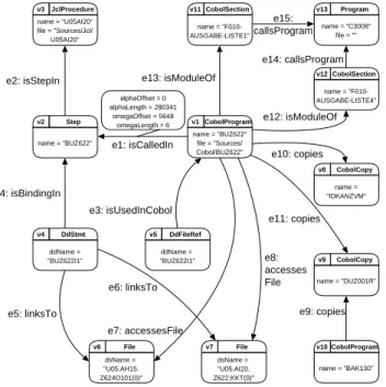
On the architectural level of abstraction, analysis may con- centrate on the relationships between system components in different programming languages. TheTGraphin figure 3 shows an extract of the software system of a large insur- ance company [34]. Due to complexity it is restricted only to some concepts that are related to JCL, Cobol and their interdependencies.
TheTGraphshows parts of the embedding of CobolPro- gramBUZ622(v1) into the whole system. It is called (e1) by StepBUZ622(v2), accesses (e7,e8) two Files (v6, v7), includes (e10, e11) two CobolCopies (v8, v9) and contains (e12, e13) two CobolSections (v11, v12) which call (e14, e15) an external Program (v13). All vertices in this exam- ple are attributed with names (name, ddname, dsname) of the modeled source code artifacts. Furthermore, all edges carry coordinate attributes that link to the concrete posi- tions in the source code. This position information is de- picted in figure 3 only for edge e1as an example. It is used together with the file attributes of JclProcedures and Cobol- Programs to visualize the associated source code fragments in theGUPROsource code browser.
In this example a directed, vertex- and edge attributed, vertex- and edge-typedTGraphis used.
3.2. Formalization ofTGraphs
The twoTGraphexamples in figure 2 and 3 indicate that TGraphsare a scalable means for representing source code
CobolProgram v1 name = "BUZ622"
file = "Sources/
Cobol/BUZ622"
Step v2 name = "BUZ622"
JclProcedure v3 name = "U05AI20"
file = "Sources/Jcl/
U05AI20"
DdStmt v4
ddName =
"BUZ622I1"
DdFileRef v5
ddName =
"BUZ622I1"
File v6
dsName =
"U05.AH15.
Z624O101(0)"
File v7
dsName =
"U05.AI20.
Z622.KKT(0)"
CobolCopy v9 name = "DUZ001R"
CobolCopy v8
name =
"IDKANZVM"
CobolProgram v10
name = "BAK130"
CobolSection v11
name = "F010- AUSGABE-LISTE1"
CobolSection v12
name = "F010- AUSGABE-LISTE4"
Program v13
name = "C3008"
file = ""
e1: isCalledIn e2: isStepIn
e3: isUsedInCobol e4: isBindingIn
e5: linksTo
e6: linksTo
e8:
accesses File
e7: accessesFile
e9: copies e11: copies
e10: copies e12: isModuleOf e13: isModuleOf
e14: callsProgram e15:
callsProgram
alphaOffset = 0 alphaLength = 280341
omegaOffset = 5648 omegaLength = 6
Figure 3. Multi-language system (extract)
in various reengineering applications on different levels of abstraction. Before proposingTGraphsas abstract syntax for a general reengineering interchange format the formal foundation has to be specified. In [13, 16]TGraphsare in- troduced as a mathematical structure using theZspecifica- tion language [47].
The basic elements (Element) of TGraphs are vertices (Vertex) and edges (Edge), which are identified through nat- ural numbers. An edge may occur as incoming or outgoing, which is represented in the Dir attribute.
Element::=vertexhhN iijedgehhN ii Vertex==ran vertex
Edge==ran edge Dir::=injout
TGraphelements may be associated with a type and with attribute value pairs. Type identifiers (TypeId) and attribute identifiers (AttrId) are derived from a given set Id. The as- sociation between attribute identifiers and their values is de- fined by a finite partial function AttributInstanceSet.
[Id;Value] TypeId==Id AttrId==Id
AttributeInstanceSet==AttrId!77 Value
Based on these definitions,TGraphsare specified by the
Z schema in figure 4. TGraphs consist of finite and injec- tive sequences of vertices (V) and edges (E), respectively.
An incidence function associates to each vertex the se- quence of its incident edges together with their direction in- formation. Types and attributes of graph elements are given
by the type and value functions. Further predicates ensure, that the incidence lists are injective [p1], that every edge occurs in exactly one incidence list as outgoing and in ex- actly one incidence list as incoming [p2], and that type and attribute functions are restricted to existing graph elements [p3], [p4]. ThisZschema gives the formal foundation for the definition of the concreteGraXnotation for interchang- ingTGraphsin section 5.
TGraph V:iseq Vertex E:iseq Edge
:Vertex!77 seq(EdgeDir) type:Element!77 TypeId
value:Element!77 AttributeInstanceSet
2ran V!77 iseq(EDir) [p1]
8e:ran E9
1
v;w:ran V
(e;in)2ran((v))^
(e;out)2ran((w)) [p2]
dom type=V[E [p3]
dom value=V[E [p4]
Figure 4.ZschemaTGraph
4. Conceptual modeling with EER
Being a plain structural means for describing,TGraphs have no meaning of their own. The meaning ofTGraphs corresponds to the context in which they are exchanged.
This application context determines which vertex and edge types, which attributes and which incidence relations are modeled. Conceptual modeling techniques are used to de- fine classes ofTGraphsrepresenting this application related knowledge.
In order to provide the definition ofTGraphclasses on a contemporary semantic level, we use theEER/GRALap- proach to graph-based modeling [16]. Classes ofTGraphs are defined through extended entity relationship diagrams (EER) which may be annotated with additional restrictions inGRAL(Graph Specification Language) [21]. InEERdia- grams entity types and relationship types are used to specify vertex types and edge types together with their attribute def- initions and incidences. Multiple generalization is allowed for vertex and edge types. Further structural information can be modeled by using aggregations.
EERdiagrams allow to describe the concepts of the soft- ware systems to be represented in reengineering tools. They can be viewed as conceptual models of the application do- main determining the meaning of exchanged data.
4.1. Representing application-specific knowledge throughEERmodels
As said before, conceptualEERschemas restrict the set ofTGraphsto those graphs representing application related data. Each reengineering task needs its specific source code representation. E. g. the examples of analyzing fine- grained program structures or of inspecting coarse-grained source code interdependencies in section 3 require different application-specific conceptual models.
Fine-grained conceptual model (code level)
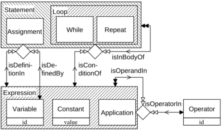
The EER model2 in figure 5 defines a small conceptual model for fine-grained program understanding. It defines the concepts Statement, Expression and Operator and their connecting relationships. Statements are subdivided into Assignments and Loops which themselves are (disjointly) specialized into While or Repeat loops. The concepts Vari- able, Constant, and Application are generalized into the concept Expression. The subconcepts of Assignment, Loop and Application are modeled as aggregations. E. g. an Ap- plication consists of exactly one Operator and at least one Expression.
Assignment Statement Loop
Expression
isInBodyOf isCon-
ditionOf isDe-
finedBy isDefini- tionIn
isOperatorIn isOperandIn
id Variable
While Repeat
Application value
Constant
id Operator
Figure 5. Fine grained conceptual model
The TGraphin figure 2 representing the program frag- ment in figure 1 is one possible instance of this conceptual model.
Multi-language conceptual model (architectural level) On an architectural level the reengineer might be inter- ested in the main building blocks such as JclProcedures, Programs, CobolCopies or Files and their interconnection.
2In the concrete notation of theEERdialect used for presentation, ver- tex types are represented by rectangles and edge types by (directed) arcs.
Generalization is depicted by the usual triangle notation but also by graphi- cally nesting object types. Within both notations an abstract generalization is symbolized by hatching. Aggregation is depicted by a diamond at the vertex type rectangle. Relationship cardinalities are given by an arrow no- tation at the participating vertex types.
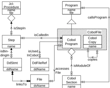
The conceptual model in figure 6 depicts an extract of the multi-language conceptual model [34] related to the Cobol and JCL part. Here CobolPrograms may include Cobol- Copies and contain CobolSections which may call Pro- grams. CobolPrograms are called by Steps which are col- lected in JclProcedures. By using DdStmts and DdFileRefs CobolPrograms access Files.
name file Program
Cobol Copy name
linksTo
isCalledIn isStepIn
isBin- dingIn
callsProgram
isModuleOf isUsed
InCobol
accesses File File
dsName Step
name
DdStmt ddName
DdFileRef ddName
Cobol Section
name
CobolFile
copies Cobol
Program name
file Jcl- Procedure
Figure 6. Multi-language conceptual model This conceptual model defines the schema forTGraphs like the one in figure 3.
4.2. Formalization ofEERmodels
The formal foundation ofEERmodeling of graph struc- tures is defined in [9] byZspecifications. EachEERmodel denotes a set of correspondingTGraphsby describing valid vertex and edge types including their attribute and inher- itance structures, the allowed connection between vertex types and edge types, and additional constraints (like de- gree restrictions).
4.3. RepresentingEERmodels throughTGraphs Since EER diagrams are structured information them- selves, they may be described asTGraphsas well. The class ofEER TGraphscan be defined by a metaEERmodel in such a way, that all the TGraphsrepresenting anEER di- agram are compliant to this meta schema [14]. This meta schema is given in figure 7.
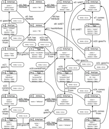
Entity types are modeled inEER TGraphsas EntityType and relationship types as RelationshipType vertices. The in- cidences are modeled by comesFrom and goesTo edges. At- tribute vertices representing attribute names can be associ- ated by hasAttribute edges to EntityType and Relationship- Type vertices. Attribute domains are specified using Do- main vertices. Aggregation-like relationships are modeled
EntityType
dir: bool
RoleType RelationshipType
=2
relates Type
injective: bool limits : ININ
(relates) goesTo
abstract : bool
Attribute Domain
has Domain hasAttribute
isA ERItem
isART (isA) isAET
(isA)
name : string
(relates) comes From
Figure 7.EERmetaschema
by vertices of type RoleType. isAET edges and isART edges describe generalization hierarchies for entity types and re- lationship types.
According to theEERmeta model in figure 7 the con- ceptual models in figure 5 and 6 can be represented by the TGraphsgiven in figures 8 and 9.
RoleType v8 name="isConditionOf"
dir = true injective = false abstract = false EntityType
v1 name =
"Statement"
abstact = false limits = (1,n)
limits = (0,n) RoleType v9 name = "isInBodyOf"
dir = true injective = false abstact = false
e1:comes From
EntityType v3
name ="Loop"
abstact = true
e2:goesTo
e4:isAET v4 EntityType
name ="while"
abstact = false
EntityType v5
name = "Repeat"
abstact = false
e5:isAET
e6:isAET
limits = (0,n)
e7: goesTo
RoleType v7 name = "isDefinition"
dir = true injective = false abstract = false RoleType
v6 name = "isDefinedBy"
dir = true injective = false abstract = false EntityType v2
name ="Assignment"
abstact = true
limits = (0,n)
e9:
goesTo
limits = (0,n)
e8:goesTo e3: isAET
EntityType v10
name ="Expression"
abstact = true
limits = (1,1) e10:
comesFrom limits = (1,1)
e11:comes From
RoleType v15 name="isOperandIn"
dir = true injective = false abstract = false limits = (1,n)
e12:comes From
RoleType v16 name = "IsOperatorIn"
dir = true injective = false abstract = false
EntityType v14
name ="Operator"
abstact = false limits = (1,1)
e19:
comesFrom
EntityType v13
name ="Application"
abstact = false
limits = (0,n) e17:
goesTo
limits = (0,n) e18:
goesTo
EntityType v12
name ="Constant"
abstact = false EntityType
v11
name ="Variable"
abstact = false
e16:
isAET e15:isAET
e14:isAET
limits = (1,1)
e13:
comesFrom
e22:hasAsAttribute
Attribute v18
name = "value"
e21:hasAsAttribute
Attribute v17
name = "id"
e20:hasAsAttribute
Figure 8. Fine-grained conceptual model asEER TGraph
The examples presented so far give evidence that TGraphs define an abstract syntax for representing in- stances and schemas for interchanging reengineering data.
Because theEERmeta model itself is anEERmodel it is representable and exchangeable as anEER TGraphas well.
e29: comes From
EntityType v1
name =
"JclProcedure"
abstact = false
Attribute v2
name = "file"
e1: has
Attribute e2: has
Attribute
EntityType v3
name =
"Program"
abstact = false
RoleType v4
name = "isStepIn"
dir = true injective = false abstract = false
limits = (1,1)
e4: goesTo
limits = (0,n)
e12:
comes From
EntityType v5
name = "Step"
abstact = false e15:goesTo
limits = (0,n)
e16:comes From
EntityType v7
name =
"CobolProgram"
abstact = false limits = (1,1)
EntityType v10
name =
"CobolCopy"
abstact = false v6
name = "isCalledIn"
injective = false abstract = false Relationship
Type
v9
name = "copies"
injective = false abstract = false Relationship
Type EntityType v8
name =
"CobolFile"
abstact = true
e10: goesTo
limits = (0,n) e7: comes
From
limits = (0,n)
e8: isAET
e9: isAET e3: isAET
v11 name =
"isBindingIn"
injective = false abstract = false Relationship
Type limits = (1,1)
e17:
goesTo
limits = (0,n)
e22:
comes From
EntityType v12
name =
"DdStmt"
abstact = false
v13 name =
"isUsedInCobol"
injective = false abstract = false Relationship
Type limits = (0,1)
e19:
goesTo
limits = (0,n)
e23:comes From
EntityType v14
name =
"DdFileRef"
abstact = false
limits = (0,n)
RoleType v15 name = "isModuleOf"
dir = true injective = false abstract = false
e20: goesTo
limits = (0,n) e24: comes
From
EntityType v16
name =
"CobolSection"
abstact = false
v17 name =
"linksTo"
injective = false abstract = false Relationship
Type limits = (1,n)
e27:
comes From
EntityType v18
name =
"File"
abstact = false
e30:goesTo
limits = (1,n) v20
name =
"accessesFile"
injective = false abstract = false Relationship
Type
limits = (0,n)
e28:
goesTo e18:comesFrom
limits = (0,n)
v19 name =
"callsProgram"
injective = false abstract = false Relationship
Type limits = (0,n)
e21: goesTo
limits = (0,n)
Attribute v21
name = "dsName"
Attribute v22
name = "ddName"
e26: has Attribute e25: has
Attribute
Attribute v23
name = "file"
e31: has Attribute
e6:has Attribute e5: has
Attribute
e14: has Attribute e13: has
Attribute e11: hasAttribute
Figure 9. Multi-language conceptual model asEER TGraph
5. GraX
Having agreed on the abstract syntax of an exchange for- mat, a concrete notation has to be fixed forTGraphs. It has to be ensured that translation between almost any internal representation and this format can be done easily. We have chosen XML [54] as a non proprietary interchange mecha- nism which fits to current internet technology.
XML offers a meta language for defining structures of documents in the world wide web. These structures are de- fined in document type definitions (DTD). Hereby the ele- ments of documents including their attributes and consists- of relationships are specified. Concrete documents are de- scribed in a markup language according to the structures de- fined in their DTD. These DTDs enable a distributed and in- dependent development of tools for visualization and anal- ysis.
5.1.GraX document type definition
In a reengineering interchange format instance data have to be exchanged together with their conceptual models. Pro- ceeding naively, every conceptual model can be translated into an appropriate DTD and the corresponding instance data is described in a suited XML document. Unfortunately this policy leads to different exchange formats for schemas and instances. As shown in section 4 schema and instance
information can be based on the same abstract syntax. Thus inGraXonlyTGraphshave to be exchanged.
<!ELEMENT grax (vertexjedge)*>
<!ATTLIST grax
schema CDATA #REQUIRED>
<!ELEMENT vertex (attr)*>
<!ATTLIST vertex
id ID #REQUIRED
type CDATA #IMPLIED lambda IDREFS #IMPLIED>
<!ELEMENT edge (attr)*>
<!ATTLIST edge
id ID #REQUIRED
type CDATA #IMPLIED alpha IDREF #REQUIRED omega IDREF #REQUIRED>
<!ELEMENT attr EMPTY>
<!ATTLIST attr
name CDATA #REQUIRED value CDATA #REQUIRED>
Figure 10. XML document type definition forTGraphs (grax.dtd)
According to the formal specification ofTGraphsin sec- tion 3.2 the TGraphdocument type definition is given in figure 10. AGraX document is attributed with its schema name and consists ofvertexandedgeelements. Both kinds of elements may contain attributes (attr) which consist of names and avalues. Vertexandedgeelements are identi- fied by a required identifier idand both may be attributed with atypeidentifier. The ordering of vertices and edges is given by their textual position. Incidences including the ori- entation of edges are described as requiredalphaandomega attributes withinedgeelements. Furthermore, an optional attributelambdacan be associated withvertexelements de- scribing the ordering of incident edges. Alpha,omegaand lambdarefer to the identifiers ofvertexandedgeelements.
XML does not support different name spaces for identi- fiers of different elements. So, in an additional constraint, lambda attributes have to be restricted to identifiers refer- encing edge elements, while alpha and omega attributes refer to vertex elements. For distinguishing verticesand edgeswe propose naming vertices beginning with ”v” and edges with ”e” followed by an integer. Attributevaluesin attrelements are of type string (CDATA). For notating con- crete GraX documents suitable casting mechanisms have to be established for transferring values of other types into strings and vice versa.
5.2. Exchanging data usingGraX
With respect to theGraX document type definition, the TGraphsrepresenting reengineering related data can be ex- changed by simple ASCII texts. AGraXdocument specify-
ing the multi-language system graph of figure 3 is given in figure 11.
1 <?xml version=”1.0” ?>
2 <!DOCTYPE grax SYSTEM ”grax.dtd”>
3 <grax schema = ”http://www.gupro.de/schemas/multi.scx”>
4 <vertex id = ”v1” type = ”CobolProgram”>
5 <attr name = ”name” value = ”BUZ622”/>
6 </vertex>
7 . . .
8 <edge id = ”e1” type = ”isCalledIn”
9 alpha = ”v1” omega = ”v2”>
10 <attr name = ”alphaOffset” value = ”0”/>
11 <attr name = ”alphaLength” value = ”280341”/>
12 <attr name = ”omegaOffset” value = ”5648”/>
13 <attr name = ”omegaLength” value = ”6”/>
14 </edge>
15 . . . 16 </grax>
Figure 11. Multi-language graph inGraX (extract)
GraX documents start with specifying the XML version and the underlying DTD in lines 1 and 2. This initial in- formation is followed by the graph definition between the
<grax> and </grax> tags which starts with the schema information (line 3). The CobolProgramvertex v1 is de- scribed as avertexelement in lines 4–6. Itsnameattribute with valueBUZ622is specified in theattrelement in line 5.
Analogously lines 8–14 show the edgee1connectingv1and v2including its attributes.
Incidence lists describing the ordering of edges incident to a vertex are shown in figure 12 which is an extract of theGraX document describing theTGraphin figure 2. The vertexv3is incident to the edgese4,e9,e12, ande15in this order.
1 . . .
2 <vertex id = ”v3” type = ”Variable”
3 lambda = ”e4 e9 e12 e15”></vertex>
4 . . .
Figure 12. Incidence lists inGraX
A TGraph representing schema information has been shown in figure 6. SchemaTGraphs like this can also be interchanged asGraX documents. A part of theGraX doc- ument describing this schemaTGraphis given in figure 13.
These examples show that the TGraph document type definition provides a structure to describe instance and schema information related to reengineering information on different levels of abstractions. ASCII texts following this definition, of course, only describeTGraphswithout check- ing if an instanceTGraphmatches its schemaTGraph. But this can be done easily by a component for type checking instance graphs using theGraX interchange format.
1 . . .
2 <vertex id = ”v5” type = ”entityType”>
3 <attr name = ”name” value = ”Step”/>
4 <attr name = ”abstract” value = ”false”/>
5 </vertex>
6 <vertex id = ”v6” type = ”RelationshipType”>
7 <attr name = ”name” value = ”isCalledIn”/>
8 <attr name = ”injective” value = ”false”/>
9 <attr name = ”abstract” value = ”false”/>
10 </vertex>
11 <vertex id = ”v6” type = ”EntityType”>
12 <attr name = ”name” value = ”CobolProgram”/>
13 <attr name = ”abstract” value = ”false”/>
14 </vertex>
15 . . .
16 <edge id = ”e15” type = ”goesTo”
17 alpha = ”v6” omega = ”v7”>
18 <attr name = ”limits” value = ”(0,n)”/>
19 </edge>
20 <edge id = ”e16” type = ”comesFrom”
21 alpha = ”v6” omega = ”v5”>
22 <attr name = ”limits” value = ”(1,2)”/>
23 </edge>
24 . . .
Figure 13. Multi-language conceptual model in GraX (extract)
6. Conclusion and future work
In this paper we have presented the GraX interchange format for exchanging reengineering related data.GraXof- fers a format which is both general enough to represent ap- plication specific knowledge and concrete enough to be pro- cessable and interpretable by different tools. The abstract notation ofGraXis based on a general graph model and the concrete notation is based on the recommended open XML standard. InGraX, conceptual models representing applica- tion specific knowledge and instance data are exchanged by the same document type.
Criteria for the quality of interchange formats are pro- posed in [4] and [30]. In addition to its formal foundation GraX fulfills these criteria to a large extent.
BecauseGraX combines the exchange of instance data and their conceptual modelsGraX is not restricted to fixed application domains. By defining EER models GraX of- fers an extensible interchange format. Hereby GraX sup- ports describing and exchanging reengineering data on sev- eral levels of abstraction independently from programming languages. Furthermore mappings between the exchange format and the represented sources can be defined by suit- able conceptual models (e. g. the one in figure 6). Using XML,GraX documents are based on a universal standard.
Unfortunately XML based languages blow up the size of textual descriptions. But translations into the GraX for- mat produce representations which are linear in size to the length of the source code and standard compression tools can be used during transferring these documents. (Even so
it makes sense to use abbreviations for tags and attribute names in order to shortenGraX texts.) For internal repre- sentations as used inGUPROor RIGI translations into this format and vice versa can be done in linear time with re- spect to the document size.
The interchange format proposed here is not only re- stricted to the reengineering domain. Like CDIF it can eas- ily be applied to interchanging documents between CASE tools, as well. Both, the definition of concrete requirements engineering languages (conceptual models) and concrete documents (instances) can be exchanged between interop- erable CASE tools and even between CASE and reengineer- ing tools.
Future work has to be done on implementing further filters from various intermediate representations intoGraX documents and vice versa. Due to the simplicity of theGraX DTD this seems to be an easy task from the GraX point of view. Further tools e. g. for checking the consistency of an instance document with respect to its conceptual schema can be realized based on theGraX DTD.
GraX covers the conceptual and the syntactical aspects as proposed in section 2. If one has agreed on the abstract and concrete syntax for interchanging instance and schema data, the remaining work will deal with the definition of conceptual models for certain application domains only.
Thus, to make reengineering tools interoperable, further work has to be done in agreeing on a set of application specific conceptual reference models and the description of their meaning.
Acknowledgement
We would like to thank Kostas Kontogiannis (Waterloo), Rainer Koschke (Stuttgart), Johannes Martin (Victoria) and Thomas P¨uhler (Koblenz) for valuable discussions on ex- change formats which improved this work very much.
References
[1] A. V. Aho, R. Sethi, and J. D. Ullman. Compilers, Principles, Tech- niques, and Tools. Addison-Wesley, Reading, 1986.
[2] L. O. Andersen. Program Analysis and Specialization for the C Programming Language. PhD thesis, DIKU, University of Copen- hagen, May 1994. (DIKU report 94/19).
[3] C. Berge. Graphs and Hypergraphs, volume 6 of North-Holland Mathematical Library. North-Holland, Amsterdam, 2nd edition, 1976.
[4] I. Bowman, M. Godfrey, and R. Holt. Connecting Architecture Reconstruction Frameworks. In Proceedings of the First Inter- national Symposium on Constructing Software Engineering Tools (CoSET’99), 1999.
[5] CDIF. Standardized CASE Interchange Meta-Model, EIA/IS-83.
Technical report, Electronic Industries Association, Engineering Department, Washington D. C., July 1991.
[6] Y.-F. Chen, M. Y. Nishimoto, and C. V. Ramamoorthy. The C In- formation Abstraction System. IEEE Transactions on Software En- gineering, 16(3):325–334, March 1990.
[7] K. Cremer. A Tool Supporting the Re-Design of Legacy Applica- tions. In P. Nesi and F. Lehner, editors, Proceedings of the 2nd
Euromicro Conference on Software Maintenance & Reengineering, pages 142–148, Los Alamitos, 1998. IEEE Computer Society.
[8] R. F. Crew. ASTLOG: A Language for Examining Abstract Syn- tax Trees. In Proceedings of the Conference on Domain-specific Languages, October 15-17, 1997, Santa Barbara. USENIX Associ- ation, Berkley, 1997.
[9] P. Dahm, J. Ebert, A. Franzke, M. Kamp, and A. Winter. TGraphen und EER-Schemata — Formale Grundlagen. In [15], pages 51–65.
1998.
[10] P. Dahm and F. Widmann. Das Graphenlabor, Version 4.2. Fach- bericht Informatik 11/98, Universit¨at Koblenz-Landau, Institut f¨ur Informatik, Koblenz, 1998.
[11] A. Deursen and L. Moonen. Understanding COBOL Systems using Inferred Types. In Proceedings of 7th International Workshop on Program Comprehension. IEEE, Los Alamitos, 1999.
[12] J. Ebert. Effiziente Graphenalgorithmen. Akademische Verlagsge- sellschaft, Wiesbaden, 1981.
[13] J. Ebert and A. Franzke. A Declarative Approach to Graph Based Modeling. In E. Mayr, G. Schmidt, and G. Tinhofer, editors, Graph- theoretic Concepts in Computer Science, volume 903 of LNCS, pages 38–50. Springer, Berlin, 1995.
[14] J. Ebert, A. Franzke, M. Kamp, D. Polock, and F. Widmann.
TGREP – Graphklasse zur Repr¨asentation von TGraph–bezogenen Ausdr¨ucken und Pr¨adikaten. Projektbericht 12/97, Universit¨at Koblenz-Landau, Institut f¨ur Softwaretechnik, Koblenz, 1997.
[15] J. Ebert, R. Gimnich, H. H. Stasch, and A. Winter, editors. GUPRO
— Generische Umgebung zum Programmverstehen. F¨olbach, Koblenz, 1998.
[16] J. Ebert, A. Winter, P. Dahm, A. Franzke, and R. S¨uttenbach.
Graph Based Modeling and Implementation with EER/GRAL . In B. Thalheim, editor, Conceptual Modeling — ER’96, volume 1157 of LNCS, pages 163–178. Springer, Berlin, 1996.
[17] T. Eisenbarth, R. Koschke, E. Pl¨odereder, G.-F. Girard, and M. W¨urthner. Projekt Bauhaus – Interaktive und inkrementelle Wiedergewinnung von SW-Architekturen. In J. Ebert and F. Lehner, editors, Proceedings Workshop Reengineering, Bad Honnef, 27.-28.
May 1999. University of Koblenz-Landau, Koblenz, 1999.
[18] J. Ernst. Introduction to CDIF. http://www.eigroup.org/cdif/in- tro.html, Sept. 1997.
[19] S. Even. Graph Algorithms. Pitman, Maryland, 1979.
[20] P. J. Finnigan, R. C. Holt, I. Kalas, S. Kerr, K. Kontogiannis, H. A.
M¨uller, J. Mylopoulos, S. G. Perelgut, M. Stanley, and K. Wong.
The software bookshelf. IBM Systems Journal, 36(4):564–593, 1997.
[21] A. Franzke. GRAL: A Reference Manual. Fachbericht Infor- matik 3/97, Universit¨at Koblenz-Landau, Fachbereich Informatik, Koblenz, 1997.
[22] H. Gall and R. Kl¨osch. Finding Objects in Procedural Programs: An Alternative Approach. In L. Wills, P. Newcomb, and E. Chikofsky, editors, Proceedings of the Second Working Conference on Reverse Engineering (WCRE). Toronto, Ontario, Canada, July, 14-16 1995, pages 208–216, Los Alamitos, California, 1995. IEEE Computer Society Press.
[23] J.-F. Girard and R. Koschke. Finding Components in a Hierar- chy of Modules - a Step towards Architectural Understanding. In Proceedings of the International Conference on Software Mainte- nance 1997, pages 58–65. IEEE Computer Society Press, 1997.
[24] F. Harary. Graph Theory. Addison-Wesley, Reading, 1969.
[25] R. Holt. An Introduction to TA: The Tuple-Attribute Language.
http://www.turing.toronto.edu/holt/papers/ta.html, 1997.
[26] M. H¨ummerich. Entwicklung und prototypische Implementa- tion eines konzeptionellen Modelles zum Reverse-Engineering von ANSI85-COBOL-Programmen. Studienarbeit S 380, Universit¨at Koblenz-Landau, Fachbereich Informatik, Koblenz, Juni 1995.
[27] ISO 10303 (STEP), 1994.
[28] R. Kazman and J. Carri`ere. Playing Detective: Reconstructing Soft- ware Architecture from Available Evidence. Automated Software Engineering, 6(2):107–138, April 1999.