A Short Introduction to the GXL Software Exchange Format
Richard C. Holt University of Waterloo Department of Computer Science
Waterloo N2L 3G1, Canada
holt@plg.uwaterloo.ca
Andreas Winter
University of Koblenz-Landau Institute for Software Technology
D-56016 Koblenz, Germany
winter@uni-koblenz.de
Abstract
GXL (Graph Exchange Language) is designed to be a standard exchange format for information that is de- rived from software. This exchange is done by repre- senting the information as a graph and transcribing the graph to XML. This paper presents an example of a graph representing program information and shows how such a graph is encoded in XML The syntax of GXL is given by an XML DTD. The form of GXL graphs is given by a schema (an UML class-diagram) which in turn can be exchanged as a GXL graph.
1. Introduction
This paper gives a brief introduction to the GXL (Graph Exchange Language) software exchange format (SEF) [Ebert et al. 1999], [Holt et al. 2000]. GXL is designed to be a standard for exchanging information derived from programs, and more generally for exchanging in- formation which is conveniently represented as a graph.
GXL is represented in XML. We give an example of a diagram that represents information about a program and shows how that information is translated to GXL and hence to XML. As well, the syntax of GXL is given in terms of DTD (Document Type Definition) [W3C, 1998].
2. Data as Typed Graphs
Figure 1 shows a graph that represents a fragment on a program, in which procedure P calls procedure Q and references variable V. As well, procedure Q references variable W. Procedure P is located in file main.c while Q is located in test.c. Variable V is declared on line 225 while W is declared on line 316. The calls and refer- ences in the program occur on various source lines in the program (lines 127, 42 and 27).
It is common to represent data about software as dia- grams similar to Figure 1. Such a diagram is an attrib- uted (File and Line are attributes), typed (Proc and Var are types), directed graph, or simply a typed graph for short. This mathematical model (typed graphs) provides a clear meaning of the data we are exchanging, aside from any particular way we choose to encode the data as a stream of bytes.
Figure 1. Sample typed graph with attributes
3. Representing a Graph in XML
Since XML has become a standard for transmitting streams of data, we have chosen to encode GXL dia- grams in XML. As an example, Figure 2 represents the graph from Figure 1 as written in XML (using the GXL standard).
As can be seen in Figure 2, each node is described within the tagging constructs <node> and </node>.
For example, lines 2-4 in the figure specify that node P of type Proc has a File attribute whose value is main.c.
Lines 14-16 specify that edge (P, Q) of type Call has a Line attribute whose value is 42. In general each node or edge can have any number of attributes.
<gxl>
<node id="P" type="Proc">
<attr name="File" value="main.c" />
</node>
<node id="Q" type="Proc">
<attr name="File" value="test.c" />
</node>
<node id="V" type="Var">
<attr name="Line" value="225" />
</node>
<node id="W" type="Var">
<attr name="Line" value="316" />
</node>
<edge begin="P" end="Q" type="Call">
<attr name="Line" value="42" />
</edge>
<edge begin="P" end="V" type="Ref">
<attr name="Line" value="127" />
</edge>
<edge begin="Q" end="W" type="Ref">
<attr name="Line" value="316" />
</edge>
</gxl>
Figure 2. Graph in Figure 1 represented in XML (as an GXL document). The nodes (P, Q, V and W) and edges (P,Q), (P, V) and (Q, W) are repre- sented along with their types and attributes Although we will not illustrate it here, GXL can handle different programming languages, e.g., C++ and Cobol, and can handle various levels of granularity, e.g., Ab- stract Syntax Trees to Architecture. This flexibility is based on the fact that GXL can represent any typed graph.
4. Syntax of GXL
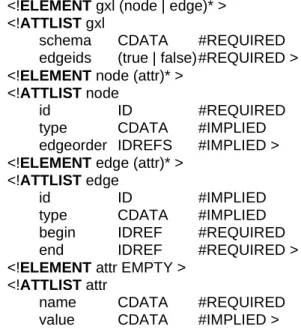
We used the DTD (Document Type Definition) notation to specify the syntax of GXL’s XML streams. Figure 3 gives a simplified version of the DTD for GXL. The complete GXL DTD representing the current state of standardizing GXL can be found at http://www.gu- pro.de/GXL.
Line 1 of Figure 3 specifies that a GXL stream consists of zero or more node and edge descriptions. Lines 2-4 state that the parameters in a GXL tag must specify the schema for the graph (this will be discussed below) and must specify whether there are to be distinct identifiers on edges. Line 5 states that a node has zero or more at-
tributes. Lines 6-9 states that each node has a required id and optional (IMPLIED) type and edgeorder attributes.
Similarly, the final 9 lines of Figure 3 specify the syntax of edges as they are represented in GXL XML streams.
<!ELEMENT gxl (node | edge)* >
<!ATTLIST gxl
schema CDATA #REQUIRED
edgeids (true | false)#REQUIRED >
<!ELEMENT node (attr)* >
<!ATTLIST node
id ID #REQUIRED
type CDATA #IMPLIED
edgeorder IDREFS #IMPLIED >
<!ELEMENT edge (attr)* >
<!ATTLIST edge
id ID #IMPLIED
type CDATA #IMPLIED
begin IDREF #REQUIRED
end IDREF #REQUIRED >
<!ELEMENT attr EMPTY >
<!ATTLIST attr
name CDATA #REQUIRED
value CDATA #IMPLIED >
Figure 3. Simplified DTD specifying the syntax of the XML stream for GXL.
5. Schemas for Typed Graphs
There are many kinds of graphs that we wish to ex- change, with various types of nodes and edges and dif- fering attributes. To handle this range of variability we used E/R diagrams (i. e. UML class diagrams) which we call schemas, such as the one given in Figure 4.
The GXL schema in Figure 4 specifies the form of graphs such as the one shown in Figures 1. This schema specifies that nodes must have the type Proc or Var and edges must have the type Call or Ref. Proc nodes have a string File attribute, while Var nodes have a string Line attribute. Both Call and Ref edges have integer Line attributes. Call edges connect Proc nodes to Proc nodes and Ref edges connect Proc nodes to Var edges.
In a similar way, graphs with other kinds of types, at- tributes and connectivity can be specified with other schemas.
Since a schema is itself a typed graph, it is can be en- coded in XML just like any other graph. Using this en- coding, the GXL notation allows schemas to be ex- changed along with actual data. This exchanging of schemas allows tools to dynamically configure them-
selves to handle the many different kinds of graphs that are useful in software analysis or in other fields of study.
Figure 4. Schema (class diagram) for graphs of the form of the one in Figure 1
6. Conclusion
This position paper has used examples to give a short introduction to the GXL software exchange format.
Since GXL is convenient for encoding any kind of typed, attributed, directed graph, it should be flexible enough to handle a wide range of source languages, lev- els of granularity, etc. Furthermore GXL is a standard- ized exchange format for any graph based application.
In the ICSE 2000 Workshop on Standard Exchange Formats (WoSEF 2000) [Sim et al., 2000] GXL was accepted as possible standard exchange format by nu- merous research groups working in the domain of soft- ware reengineering and graph transformation from in- dustries (e.g. Bell Canada (CA), IBM Center for Ad- vanced Studies (CA), Mahindra British Telecom (IN), Nokia Research Center (CA), Philips Research (NL)) and academics (e.g. groups at Universities of Bw München (DE), Koblenz (DE), Paderborn (DE), Stutt- gart (DE), Victoria (CA), Waterloo (CA)). More details about GXL can be found in [Holt et al. 2000].
References
[Ebert et al., 1999] J. Ebert, B. Kullbach, A. Winter: GraX – An Interchange Format for Reengineering Tools, in Sixth Working Conference on Reverse Engineering, IEEE Computer Society, Los Alamitos, 89-98, 1999.
[Holt et al. 2000] R. C. Holt, A. Winter, A. Schürr: GXL:
Towards a Standard Exchange Format. In Seventh Working Conference on Reverse Engineering, IEEE Computer Society, Los Alamitos, 2000.
[Sim et al., 2000] S. E. Sim, R. C. Holt, R. Koschke: WoSEF Workshop on Standard Exchange Formats, ICSE 2000 Work- shop proceedings, Limerick 2000 (http://www.cs. to- ronto.edu/~simsuz/wosef/)
[W3C, 1998] W3C: XML Working Group, Extensible Markup Language (XML) 1.0, W3C Recommendation, (http://www.w3.org/ TR/1998/REC-xml-19980210), February, 1998.