Language
Andreas Winter, Bernt Kullbach, and Volker Riediger Universit¨at Koblenz-Landau
Institut f¨ur Softwaretechnik D-56016 Koblenz,Postfach 201602
mailto:(winter|kullbach|riediger)@uni-koblenz.de http://www.gupro.de/(winter|kullbach|riediger)
Abstract.
GXL (Graph eXchange Language) is designed to be a standard exchange format for graph-based tools. GXL is defined as an XML sublanguage,which offers support for exchanging instance graphs together with their appropriate schema information in a uniform format. Formally,GXL is based on typed,attributed,ordered directed graphs, which are extended by concepts to support representing hypergraphs and hierarchical graphs. Using this general graph model,GXL offers a versatile support for exchanging nearly all kinds of graphs.
This report intends to give a short overview on the main features of GXL.
1 Motivation and Background
A great variety of software tools relies on graphs as internal data representa- tion. A standardized language for exchanging those graphs offers a first step in improvinginteroperabilitybetween these tools. For instance, a common graph in- terchange format allows building a powerful reverse engineering workbench. Such a reverse engineering workbench composes various graph-based tools like extrac- tors (e. g. scanner, parser), abstractors (e. g. query tools, structure recognition tools, slicing tools etc.), and visualizers (e. g. graph and diagram visualizer, code browser). [22] gives an overview on existing combinations of tool components used in various reverse engineering projects.
The development ofGXL (Graph eXchange Language) aims at supporting data interoperability between reverse engineering tools. GXL was ratified as standard exchange format in reverse engineering at the Dagstuhl Seminar ”In- teroperability of Reverse Engineering Tools” in January 2001 [4]. But since GXL was developed as a general format for describing graph structures, it is appli- cable in further areas of tool interoperability. Especially, GXL is used to define the graph part in the exchange format GTXL (Graph Transformation eXchange Language) [17], [34].
This paper is an extended abstract of [37].
S. Diehl (Ed.): Software Visualization, LNCS 2269, pp. 324–336, 2002.
c
Springer-Verlag Berlin Heidelberg 2002
GXL originated in a merger ofGRAph eXchange format (GraX) [7], Tuple Attribute Language (TA) [21], and the graph format of the PROGRES graph rewriting system [32]. The graph models used here were supplemented by ad- ditional concepts to handle hierarchical graphs and hypergraphs. Furthermore, GXL includes ideas from common exchange formats used in reverse enginee- ring, includingRelation Partition Algebra (RPA)[27] andRigi Standard Format (RSF) [38]. The development of GXL was also influenced by various formats used in graph drawing, e. g.daVinci[10],GML[16],XGMML (eXtensible Graph Markup and Modeling Language) [39], and GraphXML[20]. Thus, GXL covers most of the important graph formats. GXL can be viewed as a generalization of these formats.
Exchanging graphs with GXL deals with bothinstance graphsand their cor- respondinggraph schemas. Firstly, GXL offers a versatile support for exchanging all kinds of graphs based ontyped, attributed, directed, ordered graphsincluding hypergraphsandhierarchical graphs. Secondly, GXL offers means for exchanging graph schemas representing the graph structure, i. e. the definition of node and edge types, their attribute schemas and their incidence structure. Both, instance graphs and graph schemas, are exchanged by XML documents (Extended Mar- kup Language) [35].
This paper introduces into the basic concepts of GXL version 1.0 for exchan- ging instance graphs (cf. section 2) and graph schemas (cf. section 3). The lan- guage definition of GXL is given by its XML document type definition (DTD).
Section 4 summarizes the current usage of GXL.
A more comprehensive description of GXL is given in [37]. Up-to-date infor- mation including tutorials and further GXL documents are collected at http:
//www.gupro.de/GXL.
2 Exchanging Graphs
Due to their mathematical foundation and algorithmic power, graphs are a com- mon data structure in software engineering. Different graph models, e. g. direc- ted graphs, undirected graphs, node attributed graphs, edge attributed graphs, node typed graphs, edge typed graphs, ordered graphs, relational graphs, acyclic graphs, trees, etc. or combinations of these graph models are utilized in many software systems. To support interoperability of graph based tools, the under- lying graph model has to be as rich as possible to cover most of these graph models.
Such a common graph model is given bytyped, attributed, directed, ordered graphs (TGraphs)[6], [7]. TGraphs are directedgraphs, whose nodes and edges may be attributed and typed. Each type can be assigned an individual attri- bute schema specifying the possible attributes of nodes and edges. Furthermore, TGraphs are ordered, i. e. the node set, the edge set, and the sets of edges in- cident to a node have a total ordering. This ordering gives modeling power to describe sequences of objects (e. g. parameter lists) and facilitates the implemen- tation of deterministic graph algorithms. In applying TGraphs to the sketched
graph models, not all properties of TGraphs have to be used to their full extent.
These graph models can be viewed as specializations of TGraphs. Exchanging TGraphs with GXL is introduced in section 2.1
To offer support forhypergraphs andhierarchical graphs, TGraphs were ex- tended by n-ary edges and by nodes and edges containing lower level graphs.
GXL language constructs for exchanging those extended graphs are sketched in section 2.2. The complete GXL language definition in terms of an XML docu- ment type definition is given in section 2.3.
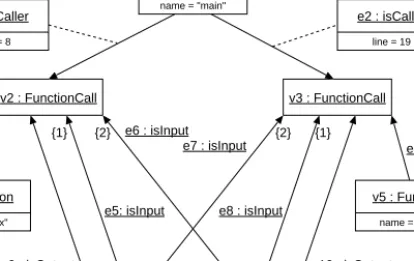
2.1 Exchanging Typed, Attributed, Directed, Ordered Graphs The UML object diagram (cf. [31]) in figure 1 shows a node and edge typed, node and edge attributed, directed, ordered graph representing a program fragment on ASG (abstract syntaxgraph) level. Function main calls functiona=max(a, b) in line8 and functionb=min(b, a) in line 19.
v1 : Function name = "main"
v4 : Function name = "max"
v6 : Variable name = "a"
v7 : Variable name = "b"
v5 : Function name = "min"
v2 : FunctionCall v3 : FunctionCall
e1 : isCaller line = 8
e2 : isCaller line = 19
e3 : isCallee e4 : isCallee
e6 : isInput e7 : isInput
e5: isInput e8 : isInput {1}
{1} {2} {2}
e9 : isOutput e10 : isOutput
Fig. 1.Typed,attributed,directed,ordered graph
The functionsmain, max and min are represented by nodes of type Func- tion. These nodes are attributed with the functions’ name.FunctionCall nodes represent the calls of functionsmax andmin.FunctionCall nodes are associated to the caller byisCalleredges and to the callee byisCallee edges.isCaller edges are attributed with a line attribute showing the line number which contains the call. Input parameters (represented by Variable nodes that are attributed with the variables’ name) are associated byisInput edges. The ordering of parameter lists is given by ordering the incidences ofisInput edges pointing toFunctionCall nodes. The first edge of typeisInput incident to function callv2 (modeling the call ofmax(a,b)) comes from nodev6 representing variablea. The second edge of type isInput connects to the second parameter b (nodev7). The incidences
of isInput edges associated with nodev3 model the reversed parameter order.
Output parameters are associated to their function calls byisOutput edges.
Exchanging graphs like the one in figure 1 requires language constructs for representing nodes, edges and their incidence relation. Furthermore, support for describing type information and attribute values is needed.
<?xmlversion = ”1.0”?>
<!DOCTYPEgxl
SYSTEM ”gxl-1.0.dtd”>
<gxl>
<graphid = ”simpleGraph”
edgeids = ”true”>
<typexlink:href=
”schema.gxl#Schema”/>
<nodeid = ”v1”>
<typexlink:href=
”schema.gxl#Function”/>
<attrname = ”name”>
<string>main</string>
</attr>
</node>
<nodeid = ”v2”>
<typexlink:href=
”schema.gxl#FunctionCall”/>
</node>
<nodeid = ”v3”>
<typexlink:href=
”schema.gxl#FunctionCall”/>
</node>
<nodeid = ”v4”>
<typexlink:href=
”schema.gxl#Function”/>
<attrname = ”name”>
<string>max</string>
</attr>
</node>
<nodeid = ”v5”>
<typexlink:href=
”schema.gxl#Function”/>
<attrname = ”name”>
<string>min</string>
</attr>
</node>
<nodeid = ”v6”>
<typexlink:href=
”schema.gxl#Variable”/>
<attrname = ”name”>
<string>a</string>
</attr>
</node>
<nodeid = ”v7”>
<typexlink:href=
”schema.gxl#Variable”/>
<attrname = ”name”>
<string>b</string>
</attr>
</node>
<edgeid = ”e1”
from = ”v2” to = v1”>
<typexlink:href=
”schema.gxl#isCaller”/>
<attrname = ”line”>
<int>8</int>
</attr>
</edge>
<edgeid = ”e2”
from = ”v3” to = v1”>
<typexlink:href=
”schema.gxl#isCaller”/>
<attrname = ”line”>
<int>19</int>
</attr>
</edge>
<edgeid = ”e3”
from = ”v4” to = v2”>
<typexlink:href=
”schema.gxl#isCallee”/>
</edge>
<edgeid = ”e9”
from = ”v6” to = v2”
<typexlink:href=
”schema.gxl#isOutput”>
</edge>
<edgeid = ”e5”
from = ”v6” to = v2”
toorder = ”1”>
<typexlink:href=
”schema.gxl#isInput”/>
</edge>
<edgeid = ”e6”
from = ”v7” to = v2”
toorder = ”2”>
<typexlink:href=
”schema.gxl#isInput”/>
</edge>
<edgeid = ”e7”
from = ”v6” to = v3”
toorder = ”2”>
<typexlink:href=
”schema .gxl#isInput”/>
</edge>
<edgeid = ”e8”
from = ”v7” to = v3”
toorder = ”1”>
<typexlink:href=
”schema.gxl#isInput”/>
</edge>
<edgeid = ”e9”
from = ”v6” to = v2”
<typexlink:href=
”schema.gxl#isOutput”>
</edge>
<edgeid = ”e10”
from = ”v7” to = v3”
<typexlink:href=
”schema.gxl#isOutput”>
</edge>
</graph>
</gxl>
Fig. 2.GXL representation of graph from figure 1
Figure 2 depicts the graph from figure 1 as GXL document. XML documents start with specifying the XML version and the underlying document type defi- nition, here”gxl-1.0.dtd”(cf. figure 3). The body of a GXL document is enclosed
in <gxl>tags. The GXL document in figure 2 contains a graph with a unique
identifier”simpleGraph”. The graph refers to its associated graph schema object Schema(cf. section 3) stored in fileschema.gxl.
Nodes and edges of a given graph are depicted by<node>and<edge>ele- ments which can be addressed by theiridattribute. Incidence information of ed-
ges including edge orientation is stored infromandtoattributes within <edge>
tags. Ordering of incidences is also modeled here. Attributes fromorderandtoor- derrepresent the position of an edge in the incidence list of its start and target node.
Node and edge types are represented by links pointing to the appropriate schema information. These links are enclosed in<type>elements.
<node> and <edge> elements may additionally contain further attribute
information. <attr> elements describe attribute names and values. Like OCL [36], GXL provides <bool>, <int>, <float>, and <string>attributes. Further- more, enumeration values (<enum>) and URI-references (<locator>) to exter- nally stored objects are supported. Attribute values might be substructured.
Here, GXL offers composite attributes like sequences (<seq>), sets (<set>), multi sets (<bag>), and tuples (<tup>).
2.2 Exchanging Extended Graphs
In addition to typed, attributed, ordered, directed graphs, GXL provides the exchange ofhypergraphsandhierarchical graphs.
Hypergraphscontain n-ary edges (hyperedges) connecting not only two adja- cent nodes. Hyperedges are exchanged by<rel>elements, containing references to the incident graph objects. These references (tentacles) are stored in<relend>
elements (relation end).
Edges can be viewed as 2-ary hyperedges. Thus, in GXL, edge information can be represented bybinary hyperedges. Since graphs with (binary) edges are wi- despread in software engineering and most applications deal with graphs instead of hypergraphs, GXL offers both, the element <edge>for exchanging (binary) edges and and the element<rel>for hyperedges.
Like binary edges, tentacles may be directed or undirected as well as ordered.
The ordering of tentacles incident to their target object and the ordering of tentacles with respect to their hyperedge object is represented analogously to the ordering of incident edges by using XML attributes.
Hierarchical graphs are graphs where nodes, edges, and hyperedges contain further graphs. GXL supports exchanging hierarchical graphs by nesting those inner graphs as<graph>elements in their enclosing node, edge, and hyperedge representation.
2.3 GXL Document Type Definition
The language features of GXL for exchanging typed, attributed, directed, orde- red graphs (cf. section 2.1) and extended graphs (cf. section 2.2) are summarized in a conceptual model defining the graph model supported by GXL. The GXL graph model is completely described athttp://www.gupro.de/GXL/(graph mo- del) with its graph structure part and its attribute part.
Since GXL is an XML sublanguage, the GXL graph model had to be tran- scribed into an XML document type definition (DTD) or an appropriate XML
schema definition. To keep GXL simple and less verbose, this translation was done by hand. The resulting DTD (cf. figure 3, a commented version is given athttp://www.gupro.de/GXL (DTD)) requires only 18 XML elements. In con- trast, an appropriate DTD generated with IBMs XMI Toolkit [23] according the XML Metadata Interchange (XMI) principles for developing DTDs [26, sec- tion 3] requires 66 elements for the GXL core and and additional 63 elements for XMI and Corba related aspects.
<!–extensions–>
<!ENTITY % gxl-extension ””>
<!ENTITY % graph-extension ””>
<!ENTITY % node-extension ””>
<!ENTITY % edge-extension ””>
<!ENTITY % rel-extension ””>
<!ENTITY % value-extension ””>
<!ENTITY % relend-extension ””>
<!ENTITY % gxl-attr-extension ””>
<!ENTITY % graph-attr-extension””>
<!ENTITY % node-attr-extension””>
<!ENTITY % edge-attr-extension””>
<!ENTITY % rel-attr-extension ””>
<!ENTITY % relend-attr-extension””>
<!–attribute values–>
<!ENTITY % val ” locator|bool|int|
float|string|enum| seq|set|bag|tup
% value-extension;”>
<!–gxl–>
<!ELEMENTgxl(graph* %gxl-extension;)>
<!ATTLISTgxl
xmlns:xlink CDATA #FIXED
”www.w3.org/1999/xlink”
%gxl-attr-extension;>
<!–type–>
<!ELEMENTtypeEMPTY>
<!ATTLISTtype
xlink:type (simple) #FIXED ”simple”
xlink:hrefCDATA #REQUIRED>
<!–graph–>
<!ELEMENTgraph(type? , attr* ,
( node|edge|rel )*
%graph-extension;)>
<!ATTLISTgraph
id ID #REQUIRED
role NMTOKEN #IMPLIED
edgeids ( true|false ) ”false”
hypergraph ( true|false ) ”false”
edgemode ( directed|undirected| defaultdirected| defaultundirected)
”directed”
%graph-attr-extension;>
<!–node–>
<!ELEMENTnode(type? , attr*, graph*
%node-extension;)>
<!ATTLISTnode
id ID #REQUIRED
%node-attr-extension;>
<!–edge–>
<!ELEMENTedge(type?, attr*, graph*
%edge-extension;)>
<!ATTLISTedge
id ID #IMPLIED
from IDREF #REQUIRED
to IDREF #REQUIRED
fromorder CDATA #IMPLIED
toorder CDATA #IMPLIED
isdirected ( true|false ) #IMPLIED
%edge-attr-extension;>
<!–rel–>
<!ELEMENTrel(type? , attr*, graph*, relend*
%rel-extension;)>
<!ATTLISTrel
id ID #IMPLIED
isdirected ( true|false ) #IMPLIED
%rel-attr-extension;>
<!–relend–>
<!ELEMENTrelend(attr* %relend-extension;)>
<!ATTLISTrelend
target IDREF #REQUIRED
role NMTOKEN #IMPLIED
direction ( in|out|none) #IMPLIED startorder CDATA #IMPLIED
endorder CDATA #IMPLIED
%relend-attr-extension;>
<!–attr–>
<!ELEMENTattr(type?, attr*, (%val;))>
<!ATTLISTattr
id IDREF #IMPLIED
name NMTOKEN #REQUIRED
kind NMTOKEN #IMPLIED>
<!–locator–>
<!ELEMENTlocatorEMPTY>
<!ATTLISTlocator
xlink:type (simple) #FIXED ”simple”
xlink:hrefCDATA #IMPLIED>
<!–attribute values–>
<!ELEMENTbool(#PCDATA)>
<!ELEMENTint(#PCDATA)>
<!ELEMENTfloat(#PCDATA)>
<!ELEMENTstring(#PCDATA)>
<!ELEMENTenum(#PCDATA)>
<!ELEMENTseq(%val;)*>
<!ELEMENTset(%val;)*>
<!ELEMENTbag(%val;)*>
<!ELEMENTtup(%val;)*>
Fig. 3.GXL Document Type Definition
3 Exchanging Graph Schemas
Graphs only offer a plain structured means for describing objects (nodes) and their interrelationship (edges, hyperedges). Graphs have no meaning of their own. The meaning of graphs corresponds to the context in which they are used and exchanged. The application and interchange context determines
– which node, edge, and hyperedge types are used,
– how nodes, edges, and hyperedges of given types are related,
– which attribute structures are associated to nodes, edges, and hyperedges, and
– which additional constraints (like ordering of incidences, degree-restrictions etc.) have to be complied.
This schematic data can be described byconceptual modeling techniques. Class diagrams offer a suited declarative language to define graph classes with respect to a given application or interchange context [7].
3.1 Describing Graph Classes by UML Class Diagrams
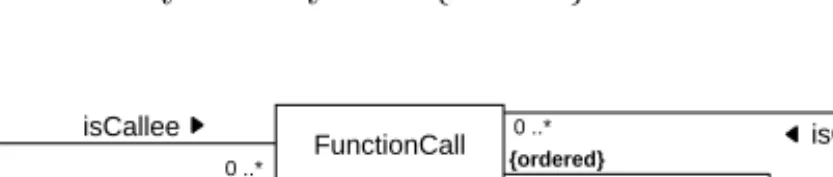
In GXL, graph classes are defined by UML class diagrams [31]. Figure 4 shows a graph schema defining classes of graphs like the one given in figure 1. Node classes (FunctionCall,Function, andVariable) are defined by classes. Edge clas- ses (isCallee,isInput, andisOutput) are defined by associations. Attributed edge classes (isCaller) are described by association classes. Like classes, they contain the associated attribute structures. The orientation of edges is depicted by a filled triangle (cf. [31, p. 155]. Multiplicities denote degree restrictions. Ordering of incidences is indicated by the keyword{ordered}.
Function name : string
Variable name : string FunctionCall
isCallee 0 ..*
1
1
0 ..* 0 ..*
0 ..*
isCaller line : int {ordered}
isCaller
isInput
isOutput 1 0 ..*
Fig. 4.Graph schema (UML class diagram)
In a similar way, UML class diagrams offer language constructs to model classes of hyperedges (diamonds) and classes of attributed hyperedges (diamonds with an associated class). The definition of hierarchical graphs requires an ad- ditional language construct representing graph classes themselves. This is done
by<<GraphClass>>stereotypes.
To offer up-to-date conceptual modeling power, the GXL schema notation provides generalization of node-, edge-, and hyperedge classes as well as aggre- gation and composition by using the appropriate UML notation.
3.2 Describing Graph Classes by Graphs
Since UML class diagrams are structured information themselves, they may be represented as graphs as well. For exchanging graph schemas in GXL, UML class diagrams are transfered into equivalent graph representations. Thus, instance graphs and schemas are exchanged with the same type of document, i. e. XML documents matching the GXL DTD (cf. section 2.3).
In contrast to the strategy proposed by XML Meta Data Interchange (XMI) [26], GXL schemas are not exchanged by XML documents according to the Meta Object Facility (MOF) [25]. XMI/MOF offers a general, but very verbose format for exchanging UML class diagrams as XML streams. By generating indi- vidual document type definitions to a given UML class diagram, it also supports exchanging instance graphs as XML documents. Next to its exaggerated verbo- sity, which contradicts the requirement for exchange formats of as compact as possible documents, the XMI/MOF approach requires different types of docu- ments for representing schema and instance graphs. Especially in applications dealing with schema information on instance level (e. g. in tools for editing and analyzing schemas), this leads to the disadvantage of different documents repre- senting the same information, one on instance level (as XML document) and one on schema level (as XML DTD). The GXL approach treats schema and instance information in exactly the same way. Schema and instance graphs are exchanged according to the DTD given in Figure 3.
name = "isCallee"
isAbstract = false isDirected = true
name = "isInput"
isAbstract = false isDirected = true name = "isCaller"
isAbstract = false isDirected = true e1 : to
limits = (0,-1) isOrdered = false
name = "Function"
isAbstract = false
name = "Variable"
isAbstract = false v7: AttributeClass
name = "line"
v9 : Int
v8: AttributeClass name = "name"
v10 : String e3 : to
limits = (0,-1) isOrdered = false
e2 : from limits = (1,1) isOrdered = false
e4 : from limits = (1,1) isOrdered = false
e7 : hasAttribute
e8 : hasDomain
e9 : hasAttribute e10 : hasAttribute
e11 : hasDomain
name = "isOutput"
isAbstract = false isDirected = true e11 : to
limits = (0,-1) isOrdered = false
e6 : from limits = (0,-1) isOrdered = false
e12 : from limits = (1,1) isOrdered = false isCallee :
EdgeClass
isCaller : EdgeClass
isInput : EdgeClass
isOutput : EdgeClass
Function : NodeClass
Variable : NodeClass schema: GraphClass
name = "Schema"
e5 : to limits = (0,-1) isOrdered = true FunctionCall :
NodeClass name = "FunctionCall"
isAbstract = false contains
Fig. 5.Graph schema (schema graph)
Figure 5 depicts the transformation of the class diagram in figure 4 into a node and edge typed, node and edge attributed, directed graph. Node classes, edge classes, attributes and their domains are modeled by nodes of suitable node types. Their attributes describe further properties. Interrelationships bet- ween surrogates of these classes are represented by edges of proper types. Attri- bute information is associated with surrogates of node classes, edge classes and associations byhasAttributeandhasDomain edges.fromandtoedges model in- cidences of associations including their orientation. Multiplicities of associations are stored inlimits-attributes. The boolean attributeisOrderedindicates ordered incidences.
Further attribute types and extended concepts like graph hierarchy, classes of hyperedges, aggregation and composition, generalization and default attribute values are modeled analogously.
GXL documents, representing instance graphs of a given graph schema re- fer to those nodes of the equivalent schema graph representing node classes (NodeClass) and edge classes (EdgeClass). The graph class itself is represented by a GraphClass node. This node is connected bycontains edges to all surro- gates of node and edge classes defined in this graph class. Schema references in GXL-documents refer to theseGraphClass nodes in GXL schema graphs (cf.
the type element of graphsimpleGraphin figure 2). In figure 5 nodes representing these class definitions are shaded. These items are refered to by the instance graph in figure 1.
GXL views edges asfirst class objectswhich have their own identity, might be typed and attributed, and might be included in a generalization hierarchy. Thus, surrogates of associations and associated classes have to be connected to furt- her information. For generality and simplicity reasons GXL schema graphs are restricted to ordinary typed, attributed, directed graphs. Hence, this edge-like information is represented by nodes as well. Although the GXL DTD provides edges connecting edges, GXL schema graphs do not use this feature.
The graph class of correct GXL schema graphs is represented as a GXL schema. A UML diagram representing thisGXL metaschemais presented with its graph part, its attribute part, and its value part athttp://www.gupro.de/GXL/
(meta schema).
Each UML class diagram defining a GXL graph schema can be represented by a graph (schema graph) matching the GXL metaschema. Thus, schema graphs are instances of the GXL metaschema. They are exchanged like all instance graphs (cf. section 2) referring to a GXL document, here representing the GXL metaschema. Since the schema graph representing the GXL metaschema is an instance of itself, it is exchanged by a self referring GXL document.
4 Using GXL
At the Dagstuhl seminar on ”Interoperability of Reverse Engineering Tools”
GXL version 1.0 was ratified as thestandard exchange formatin reverse enginee- ring [4]. Currently, various groups in software (re)engineering are implementing
GXL import and export facilities to their tools (e. g. Bauhaus [1], Columbus [8], CPPX [3], Fujaba [11], GUPRO [18], PBS [28], RPA (Philips Research), PROG- RES [29], Rigi [30], Shrimp [33]). Others are going to implement tools to support working with GXL. For instance, a framework for GXL Converters [12] and an XMI2GXL translator [40] were developed at Univ. BW M¨unchen. Further ac- tivities deal with providing graph query machines (GReQL, Univ. Koblenz) to GXL graphs or GXL-based graph databases (Univ. Aachen).
An important feature of GXL is its support for exchanging schema informa- tion. Based on this capability, reference schemas for certain standard applications in reverse engineering are currently under development. These activities address reference schemas for data reverse engineering (DRE, Univ. Namur, Paderborn, Victoria), the Dagstuhl Middle Model [24] or abstract syntaxgraph models for C++ [3], [9].
Furthermore, groups developing graph transformation tools (e. g. GenSet [15], PROGRES [29]) or graph visualization tools (e. g. GVF [19], Shrimp [33], yFiles [41]) already use GXL or pronounced to use GXL. At University of Toronto, GXL is applied within an undergraduate software engineering course to create a graph editor/layouter [5].
GXL also serves as foundation to define further graph oriented exchange for- mats. Thus, GXL defines the graph part in the exchange format GTXL (Graph Transformation eXchange Language) [17], [34]. Activities in the graph drawing community also deal with the development of an exchange format for graph layout [13]. In a panel on graph exchange formats at Graph Drawing 2001 in Vienna [14] GXL and GraphML [2] were discussed and compared. There is evi- dence of combining the structure part of GXL with the graph layout part and the modularization part of GraphML to form a general and comprehensive graph exchange format.
5 Conclusion
The previous sections gave a short introduction in the GXL Graph eXchange Language version 1.0 and its current applications.
Summarizing, GXL offers an already widely used XML sublanguage for inter- changing typed, attributed, directed ordered graphs including hypergraphs and hierarchical graphs including their appropriate schemas. By focusing on graph structure, GXL provides the core for defining a family of special suited graph exchange formats.
Acknowledgment. We would like to thank the GXL co-authors Richard C.
Holt, Andy Sch¨urr, and Susan Sim for various fruitful discussions on the de- velopment of GXL, and Oliver Heinen and Kevin Hirschmann for realizing the GXL web-site and for implementing the GUPRO related GXL tools. Thanks to Rainer Koschke for many interesting discussions on interchange formats in reverse engineering, and some helpful remarks to improve this paper. Thanks to
all the users of GXL, who currently applying and testing GXL 1.0 in their tools.
Their experience will be a significant aid to improve GXL.
References
1. Bauhaus: Software Architecture,Software Reengineering,and Program Un- derstanding. http://www.informatik.uni-stuttgart.de/ifi/ps/bauhaus/
(01.09.2001).
2. U. Brandes,M. Eiglsperger,I. Herman,M. Himsolt,and M. S. Marschall. GraphML Progress Report,Structural Layer Proposal. In to appear: Graph Drawing 2001 (Proceedings). 2001.
3. CPPX: Open Source C++ Fact Extractor.
http://swag.uwaterloo.ca/˜cppx/(01.09.2001).
4. J. Ebert,K. Kontogiannis,J. Mylopoulos: Interoperability of Reverse Engineering Tools. http://www.dagstuhl.de/DATA/Reports/01041/(18.04.2001),2001.
5. S. Easterbrook. CSC444F: Software Engineering I (Fall Term 2001),University of Toronto. http://www.cs.toronto.edu/˜sme/CSC444F/(15.09.2001),2001.
6. J. Ebert and A. Franzke. A Declarative Approach to Graph Based Modeling.
In E. Mayr, G. Schmidt, and G. Tinhofer, editors. Graphtheoretic Concepts in Computer Science, LNCS 903. Springer, Berlin,pages 38–50. 1995.
7. J. Ebert,B. Kullbach,and A. Winter. GraX – An Interchange Format for Re- engineering Tools. In Sixth Working Conference on Reverse Engineering,IEEE Computer Society,Los Alamitos,pages 89–98,1999.
8. R. Ferenc,F. Magyar, ´A. Besz´edes, ´A. Kiss,and M. Tarkiainen. Columbus - Tool for Reverse Engineering Large Object Oriented Software Systems. InProceedings SPLST 2001,Szeged,Hungary
(http://www.inf.u-szeged.hu/˜ferenc/research/ferencr_columbus.pdf, (01.09.2001)),pages 16–27. June 2001.
9. R. Ferenc,S. Elliott Sim,R. C. Holt,R. Koschke,and T. Gyim`othy. Towards a Standard Schema for C/C++. InEighth Working Conference on Reverse Enginee- ring. IEEE Computer Society,Los Alamitos,pages 49–58. 2001.
10. M. Fr¨ohlich and M. Werner. daVinci V2.0.x Online Documentation.
http://www.tzi.de/˜davinci/docs/(18.04.2001),June 1996.
11. Fujaba: From UML to Java and back again.
http://www.uni-paderborn.de/cs/fujaba/(01.09.2001).
12. GCF - a GXL Converter Framework.
http://www2.informatik.unibw-muenchen.de/GXL/triebsees/index.htm (01.09.2001).
13. Satellite Workshop on Data Exchange Formats 8th Int. Symposium on Graph Drawing (GD 2000).
http://www.cs.virginia.edu/˜gd2000/gd-satellite.html(14.09.2001),2001.
14. Graph Drawing (GD 2001),Vienna.
http://www.ads.tuwien.ac.at/gd2001/(06.12.2001),September 23.-26.,2001.
15. GenSet: Design Information Fusion.
http://www.cs.uoregon.edu/research/perpetual/dasada/Software/GenSet /index.html(01.09.2001).
16. The GML File Format.
http://www.infosun.fmi.uni-passau.de/Graphlet/GML/index.html (18.04.2001).
17. Graph Transformation System Exchange Language.
http://tfs.cs.tu-berlin.de/projekte/gxl-gtxl.html(18.08.2001).
18. GUPRO: Generic Understanding of Programs. http://www.gupro.de/
(01.09.2001).
19. GVF - The Graph Visualization Framework . http://www.cwi.nl/InfoVisu/
(01.09.2001).
20. I. Herman and M. S. Marshall. Graph XML – An XML based graph interchange format. Report INS-0009,Centrum voor Wiskunde en Informatica,Amsterdam, April 2000.
21. R. C. Holt. An Introduction to TA: The Tuple-Attribute Language.
http://plg.uwaterloo.ca/˜holt/papers/ta.html(18.4.2001),1997.
22. R. C. Holt,A. Winter,and A. Sch¨urr. GXL: Toward a Standard Exchange Format.
InSeventh Working Conference on Reverse Engineering. IEEE Computer Society, Los Alamitos,pages 162–171. 2000.
23. XMI Toolkit 1.15 (Updated on: 25.04.2000).
http://alphaworks.ibm.com/tech/xmitoolkit(01.09.2001),2000.
24. T. Lethbridge,E. Pl¨odereder,S. Tichelar,C. Riva,and P. Linos. The Dagstuhl Middle Level Model (DMM). internal note,2001.
25. Meta Object Facility (MOF) Specification.
http://www.omg.org/technology/documents/formal/mof.htm (02.09.2001), March 2000.
26. XML Meta Data Interchange (XMI) Specification.
http://www.omg.org/technology/documents/formal/xmi.htm (01.09.2001),No- vember 2000.
27. R. Ommering,L. van Feijs,and R. Krikhaar. A relational approach to support software architecture analysis. Software Practice and Experience,28(4):371–400, April 1998.
28. PBS: The Portable Bookshelf. http://swag.uwaterloo.ca/pbs/(01.09.2001).
29. A Graph Grammar Programming Environment - PROGRES. http:
//www-i3.informatik.rwth-aachen.de/research/projects/progres/main.html (01.09.2001).
30. RIGI: a visual tool for understanding legacy systems.
http://www.rigi.csc.uvic.ca/(01.09.2001).
31. J. Rumbaugh,I. Jacobson,and G. Booch. The Unified Modeling Language Refe- rence Manual. Addison Wesley,Reading,1999.
32. A. Sch¨urr,A. J. Winter,and A. Z¨undorf. PROGRES: Language and Environment.
In H. Ehrig,G. Engels,H.-J. Kreowski,and G. Rozenberg,editors. Handbook on Graph Grammars: Applications, Languages, and Tools,volume 2,World Scientific, Singapore,pages 487–550. 1999.
33. ShriMP Views: simple Hierarchical Multi-Perspective.
http://www.shrimpviews.com/(01.09.2001).
34. G. Taenzer. Towards Common Exchange Formats for Graphs and Graph Transfor- mation Systems. InProceedings UNIGRA satellite workshop ofETAPS’01. 2001.
35. Extensible Markup Language (XML) 1.0. W3C recommendation,W3C XML Wor- king Group,http://www.w3.org/XML/(17.04.2001),February 1998.
36. J. B. Warmer and A. G. Kleppe. The Object Constraint Language : Precise Mo- deling With UML. Addison-Wesley,1998.
37. A. Winter. Exchanging Graphs with GXL. In to appear: Graph Drawing 2001 (Proceedings). 2001.
38. K. Wong. RIGI User’s Manual,Version 5.4.4.
http://www.rigi.csc.uvic.ca/rigi/(18.04.2001),30. June 1998.
39. Extensible Graph Markup and Modeling Language).
http://www.cs.rpi.edu/˜puninj/XGMML/(19.08.2001),2001.
40. XIG - An XSLT-based XMI2GXL-Translator.
http://ist.unibw-muenchen.de/GXL/volk/index.htm(01.09.2001).
41. yFiles - Interactive Visualization of Graph Strucutres.
http://www-pr.informatik.uni-tuebingen.de/yfiles/(01.09.2001).