LUEHR FILTER GmbH & Co. KG Enzer Straße 26
31655 Stadthagen / Germany
guaranteed performance within the requested limit values high plant availability at low investment and operating costs flexible system adjustable to the specific application
The dry and/or conditioned dry gas cleaning with the Conditioning Rotor – Recycle Process offers proven advantages, including
Phone: +49 5721 708-0 Fax: +49 5721 708-214 E-Mail: project@luehr-filter.com
PARTNER FOR AIR POLLUTION CONTROL
Domestic Waste Incineration
Biomass Incineration
RDF Incineration
Sludge Incineration
Assessment of Dry and Semi-Dry Sorption Procedures on the Basis of Practice-Related Examples
from the Field of Incineration Plants
Rüdiger Margraf
1. Ca-based procedures ...314
1.1. Spray sorption ...314
1.2. Dry sorption with particle and gas conditioning ...315
1.3. Comparative assessment of conditioned dry sorption with other procedures ...317
1.3.1. Comparison of conditioned dry sorption with spray sorption ...317
1.3.2. Comparison: conditioned dry sorption – wet flue gas cleaning ...319
2. Combination SNCR-conditioned dry sorption – wet scrubber (TwinSorp) ...321
3. Dry sorption and use of NaHCO3 ...322
3.1. General design, advantages and disadvantages ...322
3.2. Application example domestic waste incineration in France ...323
3.3. Comparison of operating costs with conditioned sorption...324
4. Summary ...325
5. References ...325
In the course of the last years, semi-dry and conditioned dry sorption procedures with the use of Ca-based additive powder qualities as well as the dry sorption with the use of NaHCO3 gained special importance in the field of incineration plants. Starting from the prohibition of disposal in the year 2005 until today, the vast majority of new plants for waste and RDF combustion in Germany has been provided with one of these process technologies. This trend continues with regard to the new planning of WtE-plants in Europe and other parts of the world.
As a result of continuous further developments, these procedures gave proof of their reliability, performance and not least their economic efficiency in comparison to the technologies available on the market. The following lecture deals with the presentation of some established procedures and their assessment on the basis of practical examples.
It may be remarked in addition that the main focus of this lecture is on the sorption
of the acid crude gas components HCl and SOX. The suitability of the corresponding procedures for the simultaneous separation of other pollutants existing in the gas, such as e.g. dioxins/furans as well as mercury and other heavy metal compounds will not be discussed in this lecture.
1. Ca-based procedures 1.1. Spray sorption
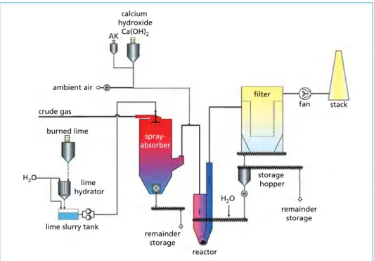
Already since many years this technology has been used for the gas cleaning downstream waste incinerators. The waste incinerators in Kassel (1986) and in Bremen (1989) serve as example of this. The basic procedure including some possible measures for optimisation is shown in Figure 1.
Figure 1: Spray sorption procedure
During the spray sorption, the separation of the acid crude gas components HF, HCl and SOx takes place by means of chemisorption with lime slurry – suspension of Ca(OH)2 in water. Normally the Ca(OH)2 is produced on site by means of a slaking process of CaO and water. Within the spray absorber finest droplets of lime slurry are brought into contact with the gas. The acid crude gases are reacting with the additive powder and in the downstream installed fabric filter they are isolated from the gas flow as dry salts.
The injection of additive powders in the wet phase increases the separation efficiency.
Further details of this process are described in [2].
AK calcium hydroxide
Ca(OH)2
ambient air
crude gas burned lime
H2O
H2O lime
hydrator
lime slurry tank
reactor
storage hopper
remainder storage remainder
storage
stack fan
filter
spray- absorber
The simple plant design and the use of CaO as additive powder are the advantages of this process. The cost advantage of CaO in comparison to Ca(OH)2 totals to about 25 percent of purchase price.
However, these advantages are faced with serious disadvantages.
• Crude gas peaks are difficult to control
• The additive powder has to be injected with a stoichiometric factor of about 2.2 up tos 2.5 related to the separated pollutants in order to achieve the emission limit values requested for waste incinerators [1].
The additional measures illustrated in picture 1 have been taken as optimisation steps at a large number of plants.
• Graded additive powder injection
In many cases, a high-reactive Ca(OH)2 is additionally injected into the gas downstream spray absorber. After adjustment of injection quantity to the crude gas input values, even crude gas peaks can be controlled as far as possible [8].
• Multiple re-circulation of additive powders and reaction products separated in the filter into a reactor upstream of filter
Particularly during realisation of high particle recycle rates, the particle re-circulation demonstrably leads to a clear improvement of degree of separation of acid crude gas components and/or to a reduction in additive powder consumption rate [5].
• The residence time of additive powder particles within the system is increased.
• Near reactor upstream filter there is a higher additive particle density – resulting reaction time in reactor more than two seconds.
• Achievement of a frequent spatial new orientation of the re-circulated additive powder particles with attachment to the filter fabric.
In spite of these optimisation steps, the comparatively high additive powder con- sumption rate remains an important disadvantage in comparison to other sorption procedures. This fact has been examined in more detail at the gas cleaning system of WIP Ludwigshafen. The results are summarised in [1].
1.2. Dry sorption with particle and gas conditioning
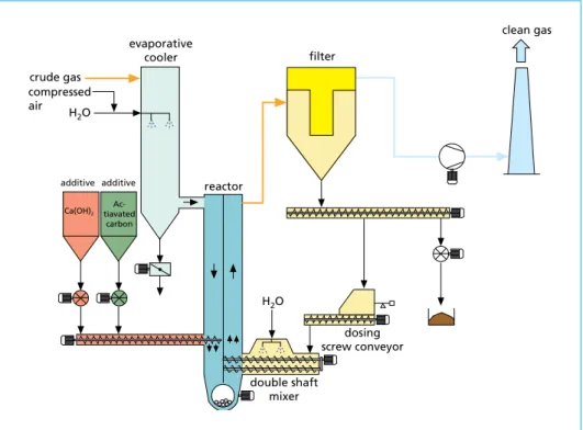
The conditioned dry sorption was developed for consequent avoidance of the disad- vantages of spray sorption technology. Figure 2 shows a possible design. In this case an evaporative cooler is used instead of a spray absorber for the adjustment of opti- mum reaction temperature. The separation of acid crude gas components takes place in reactor-filter combination by means of injection of Ca(OH)2 and multiple particle re-circulation including conditioning of recycled particulate. Further possible design types are described in [2].
Figure 2: Conditioned dry sorption
The good separation efficiency of this process is achieved by means of:
• Creation of good reaction conditions due to a particle re-circulation up to n x 100 g/Nm³.
• Improvement particularly with regard to the SO2 separation, due to the wetting of the re-circulated particulate.
• Further, even though minor reduction of gas temperature.
After optimised operating mode, this process allows particularly with regard to dry- bulb temperature and gas humidity the achievement of stoichiometric factors definitely
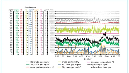
< two-fold [3, 7,9]. Figure 3 shows the records of crude gas and clean gas values for HCl and SO2 in the RDF fired power plant Stavenhagen as example for the performance efficiency of the conditioned dry sorption process.
In case of increased requirements on the separation efficiency for the acid crude gas components HCl and/or SO2 – mainly due to high input values or in case of need also for the observance of very low emission limit values – it might be reasonable to use the evaporative cooler as upstream installed reaction chamber. Besides the additional reaction time of more than two seconds, it offers excellent reaction conditions for the separation of acid crude gas components by means of the cloud of water droplets generated for the gas cooling. [5]
dosing screw conveyor double shaft
mixer
clean gas
reactor evaporative
cooler
Ca(OH)2
Ac- tiavated
carbon additive additive compressed air crude gas
filter
H2O H2O
Figure 3: Trend curves RDF fired power plant Stavenhagen
CaO can also be used for the conditioned dry sorption to benefit from the cost advan- tage of about 25 percent with regard to the procurement of additive powder compared to Ca(OH)2. In this case a dry hydrator is then used on site for the conditioned dry sorption. [3]
1.3. Comparative assessment of conditioned dry sorption with other procedures
1.3.1. Comparison of conditioned dry sorption with spray sorption Not long ago, the existing spray sorption with graded additive powder injection of two of four incineration lines of WIP Rothensee have been converted to the conditioned dry sorption. The reasons for the modification are the following:• Reliable observance of emission limit value for SO2 and HCl even in case of arising crude gas peaks.
• Clear reduction in additive powder consumption rate for the optimisation of operating costs.
Figure 4 shows the gas cleaning system after modification. The spray absorber was kept as unit but now mainly serves as evaporative cooler for the adjustment of the optimum reaction temperature. A small quantity of additive powder is still injected as suspension for the reduction of acid dew point and a graded sorption. Depending on the crude gas input values, the main quantity of additive powder is injected into the reactor upstream filter in the form of Ca(OH)2. Ca(OH)2 is produced on site from CaO by means of a dry hydrator.
2:30 3:00 4:00
42.000 36.000 30.000 24.000 18.000 12.000 6.000 Trend curves
2:00
21.10.07 3:30
0 48.000 90.000 84.000 78.000 72.000 66.000 60.000 54.000 96.000 138.000 132.000 126.000 120.000 114.000 108.000 102.000 144.000 150.000
4:30 5:00 5:30 6:00 6:30 7:00
HCI crude gas mg/m3 SO2 crude gas mg/m3 crude gas temperature °C
crude gas humidity HCI clean gas mg/m3 SO2 clean gas mg/m3
clean gas temperature °C volume flow clean gas Hg clean gas µg/m3 m3/h
14 12 10 8 6 4 2 0 16 30 28 26 24 22 20 18 32 46 44 42 40 38 36 34 48 50 µg/m3
84 72 60 48 36 24 12 0 96 180 168 156 144 132 120 108 192 276 264 252 240 228 216 204 288 300°C
28 24 20 16 12 8 4 0 32 60 56 52 48 44 40 36 64 92 88 84 80 76 72 68 96 100 mg/m3
28 20 16 12 8 4 0 32 56 52 48 44 36 64 92 88 84 76 72 68 100mg/m3
7 6 5 4 3 2 1 0 8 15 14 13 12 11 10 9 16 23 22 21 20 19 18 17 24 25
%
70 60 50 40 30 20 10 0 80 150 140 130 120 110 100 90 160 230 220 210 200 190 180 170 240 250°C
280 240 200 160 120 80 40 0 320 600 560 520 480 440 400 360 640 920 880 840 800 760 720 680 960 1.000 mg/m3
560 480 400 320 240 160 80 0 640 1.200 1.120 1.040 960 880 800 720 1.280 1.840 1.760 1.680 1.600 1.520 1.440 1.360 1.920 2.000 mg/m3
Figure 4: Gas cleaning system of WIP Rothensee
time 6:00 8:00
2.000
1.500
1.000
500 crude gas mg/m3 i.N.tr.
0:00 2:00 4:00 0
2.500
40
30
20
10
0 50 clean gas mg/m3 i.N.tr.
HCI crude gas SO2 crude gas HCI clean gas SO2 clean gas 10:00 12:00 14:00 16:00 18:00 20:00 22:00 0:00
Figure 5: Trend curves WIP Rothensee
Figure 5 shows the separation efficiency of process by means of continuously measu- red crude gas and clean gas concentrations for HCl and SO2 over a period of time of 24 hours. It is clearly visible that not least as a result of the multiple particle re-circulation and the wetting of the re-circulated particulate the limit values can reliably be kept in automatic operation even in case of HCl and SO2 peaks.
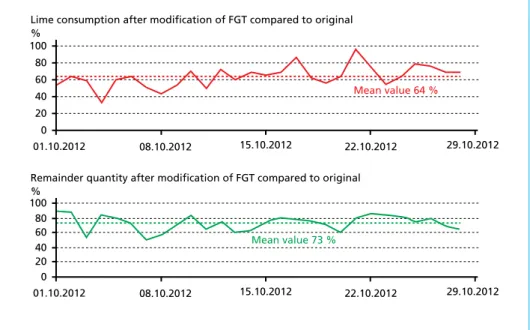
Due to the fact that in the beginning only two of four lines have been modified, it is possible to evaluate the additive powder consumption rates for the two competitively working sorption procedures. Figure 6 displays over a period of about one month the potentials for savings regarding additive powder procurement and remainder recycling for the conditioned dry sorption in comparison to the spray sorption. The savings with an under-consumption of about thirty percent are considerable. This result confirms the ranges of stoichiometry mentioned in chapters 2.1 and 2.2. It may be remarked in addition that besides the weight-related under-consumption for the conditioned dry sorption the complete additive powder quantity will be provided in the form of CaO.
The injection of an expensive, high-reactive Ca(OH)2 is completely cancelled.
08.10.2012 15.10.2012 22.10.2012 80
100 60 40 20
Lime consumption after modification of FGT compared to original
%
01.10.2012 0
29.10.2012
08.10.2012 15.10.2012 22.10.2012 80
100 60 40 20
Remainder quantity after modification of FGT compared to original
%
01.10.2012 0
29.10.2012 Mean value 73 %
Mean value 64 %
Figure 6: Additive powder savings for conditioned dry sorption versus spray sorption
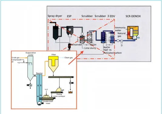
1.3.2. Comparison: conditioned dry sorption – wet flue gas cleaning In 2004 the complex wet process consisting of spray dryer, electrostatic precipitator, multi-stage scrubber and aerosol separator has been replaced by a conditioned dry cleaning system (Figure 7).
Figure 7: Modification of gas cleaning system at WIP Ludwigshafen from wet to conditioned dry
Up to the year 2008, another wet flue gas treatment system had been operated in parallel at the WIP Ludwigshafen until its conversion, thus allowing a direct comparison of both installed variants. Figure 8 shows the average values of emissions of chosen gas ingredients for the year 2005 [5].
Dosing screw conveyor
Double shaft mixer
Clean gas
Reactor Evaporative
cooler Compressed air Crude gas
Filter
NaOH TMT 15 Activated carbon Lime slurry
Remainder
Spray dryer ESP Scrubber Scrubber 3 EDV SCR-DENOX
Ammonia water
Natural gas NaOH
H2O
H2O
Figure 8: Comparison of gas cleaning system wet and conditioned dry (2005)
Concentration mg/Nm3
HCI SO2 Hg Dust C total NH3 NO2
Crude gas compenent
RRA 2 dry RRA 3 wet
0 5 10 15 20 25 30 35 40 45 50
The comparison shows that the conditioned dry sorption process is equal to the more complex wet system. The only difference is the reference variable for the separation of the acid crude gas components, i.e. SO2 for the scrubber and HCl for the conditioned dry sorption. It has to be noted in addition that regarding this application the nearly complete SO2 and SO3 separation allowed a reduction of gas temperature upstream SCR plant from previously 300 °C to 230 °C.
2. Combination SNCR-conditioned dry sorption – wet scrubber (TwinSorp)
At this point it may be remarked that in case of increased requirements on the requested emission limit values – not least also with regard to NOX – a combination of SNCR and conditioned dry sorption with downstream installed scrubber may offer advantages.
The wet stage then serves as a fine cleaning stage for HCl and SO2 as well as possibly for the separation of NH3 in the acid stage of scrubber. Subject to correct design, this process is working free from waste water. [6]
Conditioned dry sorption Acid and basic scrubber Boiler
Quench
Reactor
Double shaft
mixer SNCR H2SO4
Stack
NaOH
Double shaft mixer, quench H2O Ca(OH)2 AC
NH4OH + H2O
Figure 9: TwinSorp – Basic variant: Combination of conditioned dry sorption – acid and basic scrubbing
The basic scheme of TwinSorp process is shown in Figure 9.
The conditioned dry sorption of this process variant is operated in that way that the crude gas downstream this stage will as far as possible comply with the requirements of e.g. EU Directive 2000/76/EC. Depending on the application in question, the downstream installed fine cleaning stage serves for the
• separation of NH3
• progressing reduction in emission values e.g. for the acid crude gas components
• heat recovery.
Further details concerning this process as well as a comparative assessment with process technologies using the SCR-process can be taken from [6].
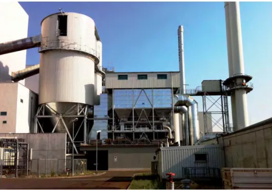
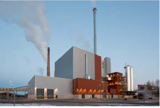
Figure 10 shows a plant in Finland which is operated in accordance with the TwinSorp process. The clean gas values for HCl, SOx and NH3 are far below the requirements of EU Directive 2000/76/EG. At this plant the wet scrubber has been realised as condenser in order to use the condensation heat for a district heating system.
Figure 10: WtE plant Oulu
3. Dry sorption and use of NaHCO
33.1. General design, advantages and disadvantages
The dry sorption with NaHCO3 competes with process technologies using Ca-containing additive powder qualities. The simple process technology of the basic variant is shown in Figure 11. The additive powder is pulverised and injected into the gas flow upstream filter. In case of crude gas temperatures larger than 140 °C, a thermal activation of sodi- um hydrogen carbonate will take place which becomes quicker with rising temperatures.
This results in the formation of a high-reactive sodium carbonate. The reaction time from the injection point of additive powder until the arrival at the filter fabric should last at least two seconds.
Normally the required emission limit values are reliably achieved in continuous ope- ration with the correct plant design and an above-stoichiometric factor of 1.2 up to max. 1.5. Particularly in case of lower temperatures the multiple re-circulation of the particles separated in the filter into the flue gas flow upstream filter can be advantageous.
Further details concerning this process as well as the advantages and disadvantages can be taken from [4].
Figure 11:
Basic variant of dry sorption with NaHCO3
Volume flow:
34.000 m3/h humid Temperature upstream quench: 250 °C NaHCO3
Mill HOK H2O
from
ESP Cond.rotor
reactor KUV
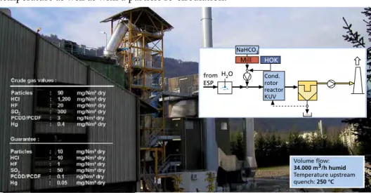
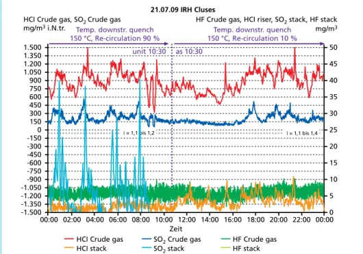
Figure 12: Application example domestic waste incineration in France
Clean Gas NaHCO2
AC Additive
Filter
Crude gas
3.2. Application example domestic waste incineration in France
Figure 12 shows an application example for a gas cleaning plant downstream domestic waste incinerator in France. Compared to the basic variant shown in Figure 11, this plant is additionally provided with an evaporative cooler for the adjustment of the gas temperature as well as with a particle re-circulation.
In 2009 extensive examinations have been realised at this plant in order to determine the influence of operating temperature and particle re-circulation on the additive powder consumption [4]. Whereas temperatures in a range between 150 °C and 180 °C do only have a very low, hardly recognisable influence, the operation with and without particle re-circulation shows a considerable difference.
Figure 13 clearly shows the influence of the particle re-circulation. In case of an adequa- tely dimensioned plant and integration of a particle re-circulation system, stoichiometric factors of smaller than 1.2 can reliably be kept in continuous operation.
Figure 13: Influence of particle re-circulation on the additive powder consumption
Source: Margraf, R.: Dry sorption with sodium bicarbonate – Really a very simple process? Examinations at a waste incinerator in France; 5th symposium; Dry crude gas cleaning for solid fuel firings and thermal process technology, Haus der Technik Essen, 2009
3.3. Comparison of operating costs with conditioned sorption
The selection of a most suited process in competition between the dry sorption with sodium bicarbonate and the conditioned dry sorption for a given application is mainly influenced by the overall costs to be expected.
In general, two essential influence factors regarding the selection of process on the basis of NaHCO3 or Ca(OH)2/CaO can be named.
SO2 Crude gas SO2 stack
HF Crude gas HF stack 1.350
600
-150
-900 -1.050 -1.200 -1.350
HCI Crude gas HCI stack
HF Crude gas, HCI riser, SO2 stack, HF stack mg/m3
-1.500 1.500
-300 -450 -600 -750 450 300 150 0 1.200 1.050 900 750
HCI Crude gas, SO2 Crude gas mg/m3 i.N.tr.
35
10 5 0 50
20 15 30 25 45 40
dp Filter: 11 bis 12 mbar, Volume flow: 26.500 m3/h dry - i calculated from current filter discharge Temp. downstr. quench
150 °C, Re-circulation 90 %
Temp. downstr. quench 150 °C, Re-circulation 10 % 21.07.09 IRH Cluses
unit 10:30 as 10:30
00:00 02:00 04:00 06:00 08:00 10:00 12:00 14:00 16:00 18:00 20:00 22:00 00:00 Zeit
i = 1,1 bis 1,2 i = 1,1 bis 1,4
• Plant size:
Increasing plant sizes entail advantages for process technologies using Ca-containing additive powders.
• Specific costs for remainders:
Higher specific costs for the disposal entail advantages for the utilisation of NaHCO3.
It may be remarked in this connection that the major part of new plants realised in Ger- many since 2005, a Ca-based process of dry sorption with NaHCO3 has been preferred.
Most of the plants have been designed for a combustion capacity of about 100,000 t per year or larger. Furthermore, as a result of the possibility of mine filling, Germany offers the advantage of a cost-effective recycling of remainder products.
4. Summary
The present lecture deals with the comparison of different sorption procedures on a dry and conditioned/semi-dry basis. Based on operating experience at hand, the con- ditioned dry sorption proved to be the best solution in most of the cases. Economic advantages compared to the alternative solutions spray sorption and dry sorption with sodium bicarbonate could be proven in many applications.
To be able to use all process-related advantages of this technology, the basic variant of the conditioned dry sorption has possibly to be adjusted to the requirements of each application by means of modifications, such as graded additive powder injection or also downstream installation of a fine cleaning stage.
At this point it may be remarked that beside the discussed systems a lot of further process variants and types of construction are offered on the market. Many of them are described in [2]. For each new application and subject to the local conditions as well as the particular boundary conditions it has to be checked which process technology or also which process variant will offer the most-suited solution.
Not only the here discussed separation of acid crude gas components but also the efficiency of corresponding process regarding the separation of other gas ingredients such as NOX, NH3, dioxins/furans, mercury and other heavy metals has to be evaluated in addition.
5. References
[1] Karpf, R.; Conrad, Y.: Sprühabsorptionsverfahren hinter Abfallverbrennungsanlagen – wie kön- nen hohe Rohgaswerte, insbesondere für SO2, beherrscht werden; 7. Tagung Trockene Abgasrei- nigung für Feuerungsanlagen und andere thermische Prozesse, Haus der Technik Essen, 2011 [2] Löschau, M.; Thomé-Kozmiensky, K. J.: Reinigung von Abgasen aus der Abfallverbrennung;
Energie aus Abfall Band 7, 2010
[3] Margraf, R.: Conditioning Rotor-Recycle Process with particle conditioning – a simple and effective process for the gas cleaning downstream waste incinerators; NAWTEC 18, Orlando/
Florida, 2010
[4] Margraf, R.: Dry sorption with sodium bicarbonate – Really a very simple process? Examinations at a waste incinerator in France; 5th symposium; Dry crude gas cleaning for solid fuel firings and thermal process technology, Haus der Technik Essen, 2009
[5] Margraf, R.: Single and multi-stage procedures for the gas treatment downstream incineration plants; VDI-Wissensforum Betriebsmittel in der Rauchgasreinigung, Bremen, 2011
[6] Margraf, R.: TwinSorp® – a simple process for increased requirements on the emission limit values i.a. for waste and RDF incinerators, considering the energy efficiency command; 6th symposium; Dry crude gas cleaning for solid fuel firings and thermal process technology, Haus der Technik Essen, 2010
[7] Plepla, K.-H.; Margraf, R.: First operating experiences gathered from the conditioned dry gas cleaning system at RDF HKW Stavenhagen; 3rd symposium; Dry crude gas cleaning for solid fuel firings and thermal process technology, Haus der Technik Essen, 2007
[8] Sindram, M.; Kremer, U.: Optimierung des Kalkverbrauchs für die Abgasreinigung; Energie aus Abfall Band 7, 2010
[9] Wradatsch, R.: Entwicklung und Betriebserfahrungen mit der konditionierten Trockensorp- tion des MHKW Ludwigshafen; 3. Fachtagung Trockene Abgasreinigung für Festbrennstoff- Feuerung und thermische Prozesstechnik, Haus der Technik Essen, 2007
Dorfstraße 51
D-16816 Nietwerder-Neuruppin
Tel. +49.3391-45.45-0 • Fax +49.3391-45.45-10 E-Mail: tkverlag@vivis.de
Bestellungen unter www. .de
oder
TK Verlag Karl Thomé-Kozmiensky
Aschen • Schlacken • Stäube
– aus Abfallverbrennung und Metallurgie –
ISBN: 978-3-935317-99-3
Erschienen: September 2013 Gebundene Ausgabe: 724 Seiten
mit zahlreichen farbigen Abbildungen
Preis: 50.00 EUR
Aschen • Schlacken • Stäube
Herausgeber: Karl J. Thomé-Kozmiensky • Verlag: TK Verlag Karl Thomé-Kozmiensky
Thomé-Kozmiensky und VersteylAschen • Schlacken • StäubeThomé-Kozmiensky
Karl J. Thomé-Kozmiensky
Aschen • Schlacken • Stäube
– aus Abfallverbrennung und Metallurgie –
M M
M M
M M
M M M
M M M
M M M
M
Der Umgang mit mineralischen Abfällen soll seit einem Jahrzehnt neu geregelt werden. Das Bundesumweltministerium hat die Verordnungs- entwürfe zum Schutz des Grundwassers, zum Umgang mit Ersatzbaustoffen und zum Bodenschutz zur Mantelverordnung zusammengefasst.
Inzwischen liegt die zweite Fassung des Arbeitsentwurfs vor. Die Verordnung wurde in der zu Ende gehenden Legislaturperiode nicht verabschiedet und wird daher eines der zentralen und weiterhin kontrovers diskutierten Vorhaben der Rechtssetzung für die Abfallwirtschaft in der kommenden Legislaturperiode sein. Die Reaktionen auf die vom Bundesumweltministerium vorgelegten Arbeitsentwürfe waren bei den wirtschaftlich Betroffenen überwiegend ablehnend. Die Argumente der Wirtschaft sind nachvollziehbar, wird doch die Mantelverordnung große Massen mineralischer Abfälle in Deutschland lenken – entweder in die Verwertung oder auf Deponien.
Weil die Entsorgung mineralischer Abfälle voraussichtlich nach rund zwei Wahlperioden andauernden Diskussionen endgültig geregelt werden soll, soll dieses Buch unmittelbar nach der Bundestagswahl den aktuellen Erkenntnis- und Diskussionsstand zur Mantelverordnung für die Aschen aus der Abfallverbrennung und die Schlacken aus metallurgischen Prozessen wiedergeben.
Die Praxis des Umgangs mit mineralischen Abfällen ist in den Bundesländern unterschiedlich. Bayern gehört zu den Bundesländern, die sich offensichtlich nicht abwartend verhalten. Der Einsatz von Ersatzbaustoffen in Bayern wird ebenso wie die Sicht der Industrie vorgestellt.
Auch in den deutschsprachigen Nachbarländern werden die rechtlichen Einsatzbedingungen für mineralische Ersatzbaustoffe diskutiert. In Österreich – hier liegt der Entwurf einer Recyclingbaustoff-Verordnung vor – ist die Frage der Verwertung von Aschen und Schlacken Thema kontroverser Auseinandersetzungen. In der Schweiz ist die Schlackenentsorgung in der Technischen Verordnung für Abfälle (TVA) geregelt, die strenge Anforderungen bezüglich der Schadstoffkonzentrationen im Feststoff und im Eluat stellt, so dass dies einem Einsatzverbot für die meisten Schlacken gleichkommt. Die Verordnung wird derzeit revidiert.
In diesem Buch stehen insbesondere wirtschaftliche und technische Aspekte der Entsorgung von Aschen aus der Abfallverbrennung und der Schlacken aus der Metallurgie im Vordergrund.