University of Ulm| 89069 Ulm | Germany Faculty of Engineering and Computer Science Department of Databases and Information Systems
Hand Gesture-based Process Modeling for Updatable Processes
Bachelor Thesis at the University of Ulm
Submitted by:
Hayato Hess
hayato.hess@uni-ulm.de
Reviewer:
Prof. Dr. Manfred Reichert
Supervisor:
Jens Kolb
2013
c
2013 Hayato Hess
This work is licensed under the Creative Commons. Attribution-NonCommercial-ShareAlike 3.0 License. To view a copy of this license, visit http://creativecommons.org/licenses/by-nc-sa/3.0/de/
or send a letter to Creative Commons, 543 Howard Street, 5th Floor, San Francisco, California, 94105, USA.
Satz: PDF-LATEX 2ε
Abstract
The increasing popularity of process models leads to the need of alternative interaction methods to view and manipulate process models. One big research field are the gesture- based manipulation methods. Although there are already works in this research area [KRR12, Dap12], they utilize only two dimensions for gesture recognition. The objective of this work is to introduce a system that manipulates process models using a three dimensional hand gesture input interface utilizing the RGB-D camera of theMicrosoft Kinect. With this, an input interface can be created that is more natural and, thus, is easier to learn and use than its two dimensional counterpart.
This work therefore discusses how gestures are recognized as well as technical imple- mentation aspects (e.g., how process models are painted, accessed and manipulated).
Furthermore, it explains the problems arising from the use of the Kinect as a hand tracking system and shows which steps have been taken to solve these problems.
Acknowledgement
First and foremost, I thank my supervisor Jens Kolb for his invaluable guidance. Second, I thank my parents and my friends for the patience and the constant support. Third, I want to thank Prof. Dr. Manfred Reichert who showed great interest in this work and agreed to be the reviewer for this thesis. Forth, I thank the department ofDatabase and Information Systemsfor providing the hardware and support for this work. Last, I thank Nintendo who’s games delighted me in the darkest hours of writing.
Contents
1 Introduction 1
2 Background 3
2.1 Process Model . . . 4
2.1.1 Central Process Model . . . 5
2.1.2 Process View . . . 5
2.2 The proView Framework . . . 6
2.3 Dynamic Time Warping . . . 7
3 REST Library 9 3.1 Interface . . . 9
3.2 Communication Protocol . . . 10
3.2.1 Communication Example . . . 11
3.2.2 Acquire List of Process Models . . . 11
3.2.3 Request a Change on a Process View or CPM . . . 14
3.2.4 The Reply to a Change View or CPM -Request . . . 17
3.3 Receiving Process Model Changes . . . 21
3.4 Parse Graph Changes . . . 21
3.5 Using the REST Library . . . 23
4 Processing Process Models 25 4.1 Creation of Process Model Blocks . . . 26
4.2 Calculation of Node Positions . . . 30
4.3 Collision Detection . . . 31
5 Kinect Library 33
5.1 Structure . . . 34
5.2 Microsoft Kinect . . . 35
5.3 Candescent NUI . . . 36
5.4 Hand Tracking . . . 37
5.4.1 Finger Count . . . 37
5.4.2 Finger Pointing . . . 40
5.4.3 Finger Position . . . 41
5.5 Gesture Recognition . . . 42
5.5.1 Gesture Format Definition . . . 43
6 ProViewKinect 45 6.1 ProViewKinect Architecture . . . 46
6.2 ProViewKinect Prototype . . . 47
6.3 Validation of the Prototype . . . 48
7 Conclusion 51
8 Summary and Outlook 53
1
Introduction
The idea of creating gesture-based user input is not new. The movieMinority Report (2002) is still well remembered because of the alternative input methods for information systems. There are already various types of gesture-based input systems available.
Therefore, creating a gesture-based information system one has to ask whether similar systems already exists and if the usability is appropriate for the specific application domain. Gesture recognition to manipulate process models based on multi-touch tablets already exist [KRR12]. However, this system utilizes only two dimensions. Systems utilizing the third dimension for gesture-based process models manipulation do not exist yet. Therefore, the decision was made to create a system capable of gesture-based process model manipulation utilizing all axis of the three dimensional space.
The usability perspective may be discussed controversially. On the one hand, a user that uses a computer with the default input is presumably faster than one that has to
rely on gestures. On the other hand, however, there are cases where a traditional input method proved to be inefficient. For example, when the user needs one of his hands for another activities like holding the steering wheel or has a handicap and is thereby unable to use a mouse or a keyboard. Another point is, that more space is required for traditional input methods. A computer with a mouse and a keyboard requires more space than a camera that can be mounted almost everywhere. Furthermore, the input with three dimensional gestures can be made very intuitive. This is important for people who have troubles working with computers or understanding a process work flow. With the three dimensional gesture-based system, they can interact with easy to learn gestures.
Therefore the vocational adjustment time would be lower for them than with traditional input methods where they might get lost. It is also more natural to interact by using the hands as an input method. Humans tend to use their hands in a conversation. Why not tell a system our needs in the same way?
This work is divided into five sections. First, Section 2, covers the basics for further sections. Second, Section 3, introducing a library with its components to communicate with a remote server to obtain process models. Third, Section 4, explaining an algorithm used to paint process models on the screen. Forth, Section 5, introducing the gesture recognition algorithm and explaining problems and their solutions when working with a Kinect as gesture recorder. Last, Section 6, showcases a three dimensional gesture- based process model manipulation prototype.
2
Background
This section covers theoretical concepts that serve as basis for the next sections. In Section 2.1, process models are covered. Section 2.2 explains a framework used to access and manipulate Process Models. Section 2.3 covers an algorithm used for gesture recognition.
2.1 Process Model
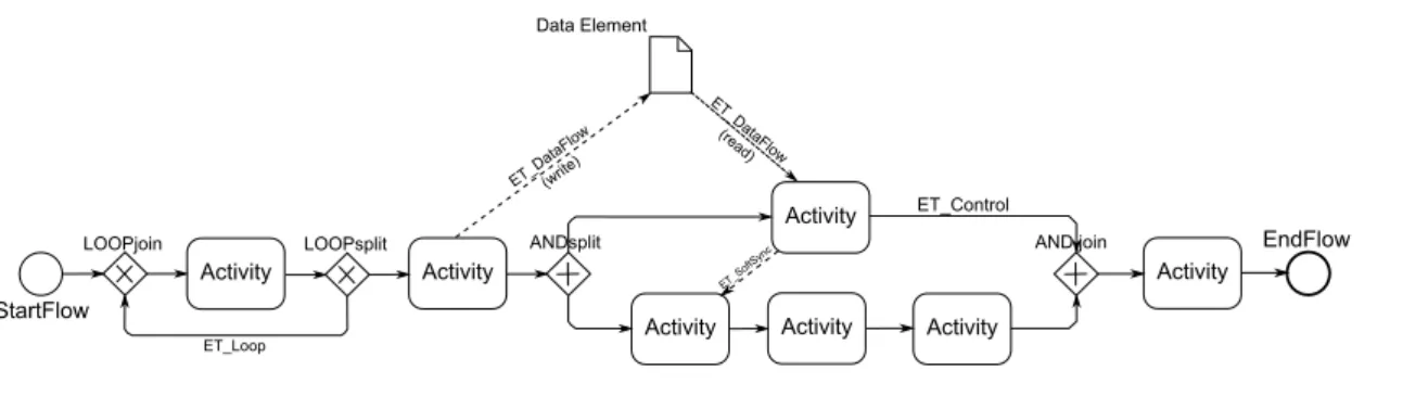
A process model is a directed graph that consists of a set ofnodes N andedges E (cf. Figure 2.1).
As described in [KKR12b, KR13a], the nodesN can be divided into:
• StartFlow, EndFlow; Thereby, the StartFlow node represents the start of the process and EndFlow its end.
• Activity nodes having exactly one incoming and one outgoing edge and represent- ing tasks in a process model.
• Gateway nodes, like ANDsplit, ANDjoin, XORsplit, XORjoin, LOOPsplit, and LOOPjoin, have multiple incoming and outgoing edges and may conditionally control the process flow. ANDsplit and Andjoin split the current path into two parallel executed paths. XORsplit and XORjoin do the same however with the restriction that only one of the two paths is executed conditionally. LOOPsplit and LOOPjoin gateways are used to conditionally repeat the paths between them.
• Data Elements represent data storages (e.g., variables or an external database).
They are accessed or written by activity nodes.
The edgesE can be divided into [KKR12b, KR13a]:
• ET_Control edges, used to show the execution order of activities and gateway nodes.
• ET_SoftSync edges, used for synchronization of parallel executed paths.
• ET_Loopedges, used to repeat the paths between the LOOPjoin and the LOOP- split node.
• ET_DataFlow edges connect data elements and activities. The direction of the edge shows whether the data element is accessed to read or write.
Definition 1(Relative Component Operator). Let P = (N, E) and P0 = (N0, E0) be process models with the nodesN, N0 and edges E, E0. ThenP\P0 = ({n ∈ N|n /∈ N0},{e∈E|e /∈E0}).
2.1 Process Model
Activity Activity
Activity
Activity Activity Activity
Activity StartFlow
EndFlow
LOOPjoin LOOPsplit ANDsplit ANDfjoin
DatafElement
ET_Da taFlow (write)
ET_Da taFlow (rea
d)
ET_Loop
ET_S oftSync
ET_Control
Figure 2.1: Example of a Process Model
Definition 2(Single Entry Single Exit Blocks). The process modelP = (N, E)consists of subgraphs. These subgraphs S = (N0, E0) withN0 ⊂ N, E0 ⊂ E are called SESE (Single Entry Single Exit) blocks, iff there is exactly one incoming and one outgoing ET_Control edge that connectsS withP\S[KR13a].
2.1.1 Central Process Model
A Central Process Model (CPM) is a process model as defined in Section 2.1. It represents the information of the corresponding business process and serves as a basis to create respective process views. Furthermore, a CPM may contain program logic required to execute it within a process-aware information system.
2.1.2 Process View
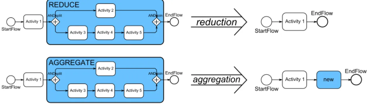
A process view is an abstraction of a specific CPM for specific needs and is created by applying a sequence ofview create operationshOp1. . . OpniwithOpi ∈ {aggregation, reduction}to a CPM.Aggregationmerges several nodes to one abstracted node and requires a SESE block to work on. Thereductionis used to remove a set of nodes from the process view (cf. Section 2.1) [KR13a].
Note that all view create operationsOpiused to create a process view do not affect the underlying CPM.
Modifying the process view and CPM, so-called update operations may be applied.
Update operations are operations that insert or delete nodes or edges in the process view and its respective CPM.
aggregation
ActivityU1 StartFlow
EndFlow
ANDsplit ANDUjoin
AGGREGATE
ActivityU2
ActivityU3 ActivityU4 ActivityU5 StartFlow
EndFlow new
ActivityU1
reduction
StartFlow
EndFlow
ANDsplit ANDUjoin
REDUCE
ActivityU1
ActivityU2
ActivityU3 ActivityU4 ActivityU5 StartFlow
EndFlow ActivityU1
Figure 2.2: Reduction and Aggregation Operation
2.2 The proView Framework
TheproView framework is based on the client-server model and, therefore, consists of a client and a server component. TheproViewClientis responsible for visualizing the process models and handling user input. The proViewServer is responsible for monitoring and performing changes to the stored process models. Furthermore, it provides aRepresentational State Transfer (REST)1interface that enables the client to retrieve, modify, add, and delete stored models.
The proView framework already has an implementation as described in [KKR12a, KKR12b, KR13b]. The proViewServer, written inJAVA, is reused. The proViewClient, written inVaadin2, is replaced by a newly created client, written in C#(cf. Section 6.1).
This new client interacts with the already implemented proViewServer and handles process graph visualization and Kinect-based user input.
1Representational State Transfer – a software architecture that can be used for distributed systems in the world wide web.
2Vaadin – a web-framework for building modern web applications.
2.3 Dynamic Time Warping
2.3 Dynamic Time Warping
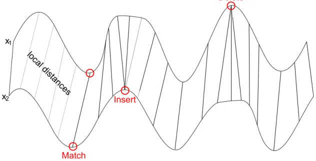
Dynamic Time Warping (DTW) is a dynamic programming algorithm used for speech recognition [MR81], because of its ability to cope with different speaking speeds and pauses. Requirements for gesture recognition are similar since different users perform the same gesture with different speeds. Therefore, DTW is able to match two input ges- ture data streams (e.g., of a camera) that may have different lengths and calculate their similarity; the so-calledDTW distance[LWZ+09]. As a distance function, theEuclidean distance is applied in an one dimensional space (cf. Figure 2.3). More precisely, the function calculates thelocal distancebetween two points of the input data streams. The DTW distance is the minimum of the sum of all local distances of each possible path.
Insert
Delete
x1
x2
Match local distan
ces
Figure 2.3: DTW Match ofx1 andx2.
1 double dtw(x1 [1..n], x2 [1..m]) {
2 // initialize Table
3 Table := [0..n, 0..m]
4 Table[0, 0] := 0
5
6 for i := 1 to n
7 Table[i, 0] := infinity
8 for i := 1 to m
9 Table[0, i] := infinity
10
11 // calculate DTW using the table
12 for i := 1 to n
13 for j := 1 to m
14 cost:= distance(x1[i], x2[j])
15 Table[i, j] := cost + minimum(
16 Table[i-1, j ], // insert rule
17 Table[i , j-1], // delete rule
18 Table[i-1, j-1] // match rule
19 )
20 return Table[n, m]
21 }
Listing 2.1: DTW Algorithm
The DTW calculation is done as follows (cf. Listing 2.1): It first initiates a table with the dimensions of the lengths of the input data streams (lines 3-4) and then calculates the DTW distance by using a distance, a minimum function, and three rules. First of all, the insert rule (line 16) that matches multiple points in the data streamx1 to one point inx2. Second, counterpart to insert, thedeleterule (line 17) used to match multiple points in x2 to one inx1. Finally,matchrule (line 18) matches one point ofx1 to one ofx2. After calculating all values in the table, the DTW distance is determined by the entry in the last row and column (line 20). The paths leading to theoptimal distance, the DTW distance, may be calculated via backtracking, if required. These paths represent the points that were matched and, therefore, contain the information about the similarities of the two data series.
In the use case of the gesture recognition, a gesture can be recognized by comparing it to a recorded gesture and calculating the DTW distance. If the gestures are very similar, the DTW distance has a low value via versa. A gesture is therefore recognized, when the DTW distance falls below a threshold.
3
REST Library
This section covers the basic structure of the «REST Library» and sheds light on how the communication with the proViewServer is done. Section 3.2 explains the communication protocol. Section 3.2 deals with getting process model updates from the proViewServer.
Section 3.4 explains how process model changes are handled. Section 3.5 showcases a communication example between «REST Library» and proViewServer.
3.1 Interface
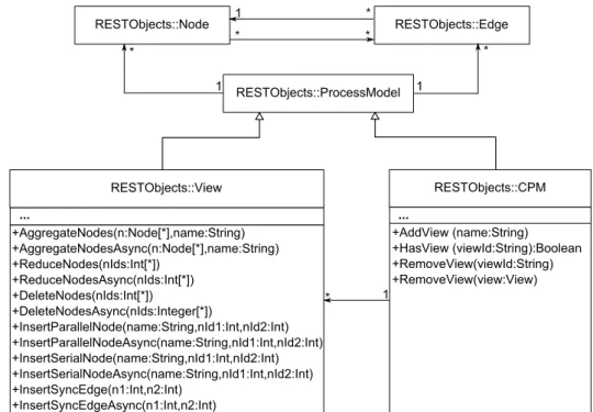
The intention of the «REST Library» is to encapsules the communication with the proViewServer and provide the user a list of Central Process Models (CPM), which is represented through aCPM class(cf. Figure 3.1). Remember, each CPM represents a whole business process and is the basis to create personalized process views. For
that reason CPM classes reference process view classes. Both, the CPM and the View classes extends themodel class. The model class contains elements required to represent a process model. The View classes provides all operations (e.g., Aggre- gateNodes, ReduceNodes, DeleteNodes, InsertSerialNode, InsertParallelNode, and InsertSyncEdge) to manipulate the View and their underlying CPM. Generally, users of the «REST Library» can handle processes as if they are stored locally; although they are stored remotely on the proViewServer.
RESTObjects::Node RESTObjects::Edge
RESTObjects::ProcessModel
RESTObjects::View
HAggregateNodes2n:Node[ ]vname:StringC HAggregateNodesAsync2n:Node[ ]vname:StringC HReduceNodes2nIds:Int[ ]C
HReduceNodesAsync2nIds:Int[ ]C HDeleteNodes2nIds:Int[ ]C
HDeleteNodesAsync2nIds:Integer[ ]C
HInsertParallelNode2name:StringvnId1:IntvnId2:IntC HInsertParallelNodeAsync2name:StringvnId1:IntvnId2:IntC HInsertSerialNode2name:StringvnId1:IntvnId2:IntC HInsertSerialNodeAsync2name:StringvnId1:IntvnId2:IntC HInsertSyncEdge2n1:Intvn2:IntC
HInsertSyncEdgeAsync2n1:Intvn2:IntC
RESTObjects::CPM
HAddView,2name:StringC HHasView,2viewId:StringC:Boolean HRemoveView2viewId:StringC HRemoveView2view:ViewC 1
1 1
1
... ...
Figure 3.1: «REST Library» Components.
3.2 Communication Protocol
In the following, the communication with the proViewServer usingREST messages is explained. At first the communication is illustrated by an example then the different types of requests and replies are explained.
3.2 Communication Protocol 3.2.1 Communication Example
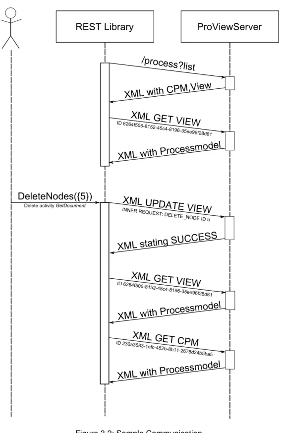
The UML sequence diagram in Figure 3.2 visualizes a communication sequence between the proViewServer and the «REST Library». At first, the «REST Library» needs to get a process view or CPM to display. Therefore, it requests theprocess list (cf. Section 3.2.2) from the proViewServer. The proViewServer replies with an XML file containing a list of CPMs and their process views (cf. Section 3.2.2). Then the «REST Library» selects a specific process view by its ID and sends a GET request containing the respective ID (cf. Section 3.2.3). The proViewServer replies to the request with the requested process model (cf. Section 3.2.4).
The process model may be used to be displayed to the user. In our example, the user deletes activity GetDocument with the ID "5". Therefore, the «REST Library»
sends an UPDATE activity request (cf. Section 3.2.3) providing the ID of the activity. In Figure 3.2, this request is successful and the server returns an XML that states this fact (cf. Section 3.2.4). Due to the successful delete request, the process view and the respective CPM are modified. Therefore, the «REST Library» sends GET requests to obtain the updated versions of the process models (cf. Section 3.2.3). The resulting process models are parsed by the «REST Library» and its observers are notified about the change.
Note that the requests in this example are all synchronous. The «REST Library» supports asynchronous requests as well (cf. Figure 3.1).
3.2.2 Acquire List of Process Models
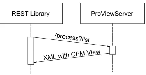
To get a list of available process models, one may simply invoke the address<ip of the proview server>:8182/process?listof the proViewServer using a HTTP GET request. The address varies depending on the configuration in the ProView.
properties settings file of the proViewServer.
The sequence diagram in Figure 3.3 demonstrates how the list is retrieved by using a synchronous request.
RESTWLibrary ProViewServer
Uprocess?l ist
XMLWwithWCPM3Vi ew XMLWGETWVIEW
IDWnQn_fOAnd
7NOQd_Oc_d7N(nd:Oee(nfQ7d7NW
XMLWwithWProcessm odel
XMLWUPDATEWVIEW
INNERWREQUEST{WDE
LETE_NODEWIDWOW DeleteWactivityWGetDocument
XMLWstating WSUCCESS XMLWGETWVIEW
IDWnQn_fOAnd
7NOQd_Oc_d7N(nd:Oee(nfQ7d7NW
XMLWwithWProcessm odel XMLWGETWCPM
IDWQ:Aa:O7
:dNefcd_OQbd7bNNdQng7dQ_bObaO
XMLWwithWProcessm odel DeleteNodes-{O}8
Figure 3.2: Sample Communication.
3.2 Communication Protocol
REST Library ProViewServer
/process?l ist XML with CPM,Vi ew
Figure 3.3: Acquire List of Process Models.
Response The proViewServer replies to the HTTP GET request with an XML file (cf. Listing 3.1) containing all available process models (i.e., CPMs and process views).
Therefore, the XML root element<models>contains a set of CPM. Each CPM has an ID (lines 3,7),name (lines 4,8), andversion number (lines 5,9). Furthermore a CPM model may comprise multiple process view models (lines 10-13). Each process view has its ownID,name, andversion(lines 10-12).
1 <?xml version="1.0" ?>
2 <models>
3 <cpm cpmID="0bf59cff-801f-4249-896b-4b9f8c50ac9a"
4 cpmName="CreditApplication"
5 cpmVersion="1"
6 />
. . .
7 <cpm cpmID="17d84280-adb3-4083-bb63-9bd9b525a94c"
8 cpmName="Complex Process"
9 cpmVersion="10">
10 <view viewID="3d548cc0-5413-41a5-928b-54b0f292d405"
11 viewName="first view"
12 viewVersion="15"/>
. . .
13 </cpm>
. . .
14 </models>
Listing 3.1: Response Containing CPM and Process Views
3.2.3 Request a Change on a Process View or CPM
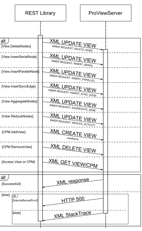
Requesting a process model based change on the list of CPM and corresponding process view, a HTTP POST request has to be sent to <ip of the proview server>:
8182/view/request(cf. Figure 3.4). Thereby, the XML payload describes the type of request and what has to be changed. The XML payload is divided into two parts.
Part 1: As shown in Listing 3.2, the first part (lines 2-6) describes what operation is requested (line 3) and which type of resource (i.e., whichCPM orVIEW) is addressed (line 6).
1 <?xml version="1.0" ?>
2 <Request>
3 <requestOperation>CREATE|DELETE|GET|UPDATE</requestOperation>
4 <resourceID>ID</resourceID>
5 <payloadFormat>XML</payloadFormat>
6 <resourceType>(CPM|VIEW)</resourceType>
7 [<query> ( viewName=name )|( Inner Request ) </query>]
8 </Request>
Listing 3.2: Update and Create Process View Requests
GET request operations is sent to the proViewServer to get the content of a process view or CPM (i.e., the actual process model). Therefore, theresourceIDof the respective process model has to be given.
CREATE and DELETE request operations are applied to add and remove process views from the proViewServer. Both the CREATE and DELETE operation require a resourceID(line 4). TheresourceIDin theDELETEoperation is used to identify the specific process view that shall be removed. In theCREATEoperation, however, it is used to define the CPM that shall serve as basis for the new process view. In addition to theresourceID, theCREATErequires aviewName(line 7) that provides the name of the process view.
3.2 Communication Protocol
REST:Library ProViewServer
XML:response alt XML:UPDATE:VIEWINNER:REQUEST::DE
LETE_NODE
[View/DeleteNodes]
[View/InsertSerialNode] XML:UPDATE:VIEWINNER:REQUEST::INSE
RT_SERIAL
[View/InsertParallelNode] XML:UPDATE:VIEWINNER:REQUEST::INSE
RT_PARALLEL
[View/InsertSyncEdge] INNER:REXML:UPDATE:VIEWQUEST::INSE
RT_SYNC_EDGE
[View/AggregateNodes] INNER:REXML:UPDATE:VIEWQUEST::AGGRE
GATE_SESE
[View/ReduceNodes] XML:UPDATE:VIEWINNER:REQUEST::RE DUCE_ACTIVITY
[CPM/AddView] XML:CREATE:VIEW
viewName
[CPM/RemoveView] XML:DELETE:VIEW
[Access:View:or:CPM] XML:GET:VIEWfCPM
alt
[Successfull]
[else] alt
[InternalServerError]
[else]
HTTP:5HH XML:StackTrace
Figure 3.4: Synchronous Method Invocations.
UPDATE request operations are used to perform changes to the schema of a process view. Therefore, theInner Requestspecifies the required update operation on the pro- cess view (line 7). Since theInner Requestis written in XML, thepayloadFormat has to be set respectively (line 5). Furthermore,resourceIDtells the proViewServer which process view to change.
Part 2: TheInner Request(cf. Listing 3.3), only used byUPDATEqueries is part of the change request and gets XML-escaped before being inserted into the outer request.
1 <?xml version="1.0" ?>
2 <de.uniulm.proView.api.entity.view.operationset.(
ViewUpdateOperation | ViewCreateOperation)>
3 <op class="de.uniulm.proView.api.entity.view.changeset.(
UpdateChangeOperation|CreateChangeOperation)">
4 (INSERT_SERIAL|INSERT_PARALLEL|INSERT_SYNC_EDGE|DELETE_NODE)|
5 (REDUCE_ACTIVITY|AGGREGATE_SESE)
6 </op>
7 [<optionSet>
8 <entry>
9 <string>nodeName</string>
10 <string>name</string>
11 </entry>
12 </optionSet>]
13 <nodeSet>
14 <int>id1</int>
. . .
15 <int>idn</int>
16 </nodeSet>
17 </de.uniulm.proView.api.entity.view.operationset.(
ViewUpdateOperation | ViewCreateOperation)>
Listing 3.3: Inner Request XML Format
Listing 3.3 shows theInner Requestand is categorized into two different types of op- erations,ViewCreateOperationandViewUpdateOperation, which are described below. Both types usenodeSet1to specify the activities affected by the change (line 13).
1set ofIntegerIDs that represent a set of activities
3.2 Communication Protocol ViewCreateOperation offers the support for ViewCreateOperation that are necessary to create a process view from a CPM (cf. Section 2.1.2) and is available by using the root elementde.uniulm.proView.api.entity.view.operationset.
ViewCreateOperation(line 2). The proViewServer expects the operation classde.
uniulm.proView.api.entity.view.changeset.CreateChangeOperationfor this request type (line 3). This operation enables all REDUCE_SESE and AGGRE- GATE_SESE operations whereasREDUCE_SESE performs a reduction andAGGRE- GATE_SESE an aggregation on the process view (cf. Section 2.1.2).
ViewUpdateOperation is used to make elementary update operations to a process view (and possibly changes to the underlying CPM). It can be accessed by using the root element de.uniulm.proView.api.entity.view.operationset.ViewUpdate Operation (line 2). The proViewServer expects the operation class de.uniulm.
proView.api.entity.view.changeset.UpdateChangeOperationfor this kind of update request (line 3). Several elementary view update operations are supported:
• INSERT_SERIALinserts a serial activity between two activities.
• INSERT_PARALLELinserts an activity in parallel to a set of activities represented by two activities. To achieve the parallel activity, theINSERT_PARALLELcommand uses anANDsplit and anANDjoingateway.
• INSERT_SYNC_EDGE inserts a synchronization edge between two activities on parallel branches.
• DELETE_NODE removes a set of activities.
3.2.4 The Reply to a Change View or CPM -Request
After the proViewServer processed the request, it replies with an XML file through a HTTP POST TCP tunnel that provides additional information depending on the type and the success of the response. The different reply types are induced by either successful or unsuccessfulCREATE,DELETE,UPDATE, andGETrequests.
Successful CREATE, DELETE and UPDATE requests If aCREATE,DELETE, and UPDATErequest succeeds, the proViewServer returns a simple XML file (cf. Listing 3.4) repeating the request (line 2), and stating that the operation was successful (line 9).
Additionally, it provides the computation time. Theresulttag is not significant.
1 <de.uniulm.proView.api.entity.rest.Response>
2 <request>
3 <requestOperation>CREATE|DELETE|UPDATE</requestOperation>
4 <resourceID>ID</resourceID>
5 <payloadFormat>XML</payloadFormat>
6 <resourceType>CPM|VIEW</resourceType>
7 <query>. . .</query>
8 </request>
9 <status>SUCCESSFUL</status>
10 <duration>0.0</duration>
11 <result>
. . .
12 </result>
13 </de.uniulm.proView.api.entity.rest.Response>
Listing 3.4: Successfull Response to CREATE,DELETE, and UPDATE operation.
Successful GET Request: Since theGETreply contains more information than the other replies, the XML file structure for this response is different. It is designed to specify a process model as described in Section 2.1.
1 <?xml version="1.0"?>
2 <template id="ID" version="16" xmlns:xsi=". . ." xsi:
schemaLocation=". . ." xmlns=". . .">
3 <name>CreditApplication</name>
. . .
4 <nodes>
5 <node id="n1">
6 <name>node name</name><description /><staffAssignmentRule/>
7 <autoStart>false</autoStart>
8 </node>
. . .
9 </nodes>
10
11 <dataElements>
12 <dataElement id="d0">
13 <type>(STRING|INTEGER|USERDEFINED)</type>
3.2 Communication Protocol
14 <name>element name</name><description/>
15 <identifierID>string</identifierID>
16 <isPublic>false</isPublic>
17 </dataElement>
. . .
18 </dataElements>
19
20 <edges>
21 <edge sourceNodeID="nb" destinationNodeID="na"
22 edgeType="(ET_CONTROL|ET_SYNC|ET_LOOP)">
23 <edgeType>(ET_CONTROL|ET_SYNC|ET_LOOP)</edgeType>
24 </edge>
. . .
25 </edges>
26
27 <dataEdges>
28 <dataEdge connectorID="0" dataElementID="nn" nodeID="dm"
29 dataEdgeType="(WRITE|READ)">
30 <dataEdgeType>(WRITE|READ)</dataEdgeType>
31 <isOptional>(true|false)</isOptional>
32 </dataEdge>
. . .
33 </dataEdges>
34
35 <startNode>ns</startNode>
36 <endNode>ne</endNode>
37
38 <structuralData>
39 <structuralNodeData nodeID="nm">
40 <type>(NT_NORMAL|NT_XOR_SPLIT|NT_XOR_JOIN|NT_AND_SPLIT
41 |NT_AND_JOIN|NT_STARTFLOW|NT_ENDFLOW|NT_XOR_SPLIT
42 |NT_ENDFLOW|NT_STARTLOOP|NT_ENDLOOP)</type>
43 <topologicalID>top id</topologicalID>
44 <branchID>branch id</branchID>
45 <correspondingBlockNodeID>ni</correspondingBlockNodeID>
46 </structuralNodeData>
. . .
47 </structuralData>
48 </template>
Listing 3.5: Successful Respond to GET Request
Listing 3.5 shows an example of an successful GET Request response. The response provides a list of nodes (lines 4-9), edges (line 20), dataElements (lines 11-18),
dataEdges(lines 27-33), andstructuralData (lines 38-47). The list ofnodesde- scribes how many nodes are in the process model and how they are labeled. The edgesET_CONTROLandET_LOOPare used to connect individual nodes of the process model to build an unidirectional graph. ET_SYNC edges are used between nodes of parallel branches to provide synchronization. StructuralData elements are used to further particularize nodes and providetype(line 40) information that specifies the exact node type. Unlike the process model definition in Section 2.1, the list ofnodes andedgesdo not contain anydata flowinformation. Instead, it is stored in the lists ofdataElementsanddataEdges.
Unsuccessful Request: When a request fails, the proViewServer either returns a HTTP 500 internal server error or an XML file containing the reason for the error (cf. Listing 3.6). The latter is parsed by the «REST Library» and a RestException object is created. Either way, the observers of the «REST Library» are notified of the exception and get either the unmodifiedWebExceptionor theRestException.
1 <de.uniulm.proView.api.entity.rest.Response>
2 <request>
3 <requestOperation>(CREATE|DELETE|UPDATE)</requestOperation>
4 <resourceID>ID</resourceID>
5 <payloadFormat>XML</payloadFormat>
6 <resourceType>(CPM|VIEW)</resourceType>
7 <query>
. . .
8 </query>
9 </request>
10 <status>FAILED</status>
11 <duration>0.0</duration>
12 <e class="java proViewServer exception class">
13 <stackTrace>
14 <trace>java stracktrace line</trace>
. . .
15 </stackTrace>
16 </e>
17 </de.uniulm.proView.api.entity.rest.Response>
Listing 3.6: Unsuccessful Request.
3.3 Receiving Process Model Changes The structure of cf. Listing 3.6 has similarities to the one of a successful request (cf. Section 3.2.4, Listing 3.4). However the status is different (line 10) as well as an additional tag is included (line 12). The latter encapsules a full Java stack trace.
3.3 Receiving Process Model Changes
Although the used REST communication protocol supports requesting process models (cf. Section 3.2.3), it does not support server side push notifications. This is essential when an external change on one of the process models occurs. Therefore, the «REST Library» has to rely on methods like polling or user initiated manual updates. These methods acquire the list of process models and compare the version numbers with the stored ones (cf. Section 3.2.2). The developers of the proViewServer might consider to add support for a notification via HTTP 1.1 Transfer-Encoding:chunked. With this, it would be possible to send short update notifications to the connected clients so that they can update their process models. TheProViewKinect (cf. Section 6) uses the
«REST Library» with a five second update interval to keep its process models up to date.
3.4 Parse Graph Changes
When a change was requested (cf. Section 3.2.3) or received (cf. Section 3.3), the
«REST Library» obtains the new process model from the proViewServer. The idea behind parsing this process model is to inform the observers of the «REST Library» not only about that a change occurred but also what has changed. Hence, the observers need only to update the modified parts of their process model representations.
As described, the changed process model is received by a successful GET request (cf. Section 3.2.4).
The «REST Library» uses three lists for this purpose. The first list contains the deleted nodes. The second is used to track the new nodes. The last contains the updated nodes at the end of the computation.
To fill the lists, the algorithm parses the XML file for the nodes (Listing 3.7). If a node exists in the list of old nodes, it is removed (line 12). If it was changed, it is copied into the list of updated nodes (line 19). If not, the algorithm creates a new node and stores it in the list for new nodes (line 23).
At the end, the first list contains all elements that existed in the old but not in the new graph, the deleted nodes. The second list contains all new nodes since all new nodes are added to it on creation. The third list contains all updated nodes since the nodes in this list were found in the list of old nodes but with different values. These three lists are then sent to the observers so that they can update their process models.
A modified version of this algorithm is used to track changes on the edges.
1 // contains all old nodes, at the end only the deleted nodes
2 Dictionary<int, Node> oldNodes = model.NodeDictionary;
3 // empty, will contain all new nodes
4 List<Node> addedNodes = new List<Node>();
5 // empty, will contain all reused nodes
6 List<Node> updatedNodes = new List<Node>();
7
8 foreach (XmlNode n in nodes){
9 if (oldNodes.ContainsKey(id)){
10 // reuse old node
11 node = oldNodes[id];
12 oldNodes.Remove(id);
13
14 // check if the node has changed
15 if (!node.Name.Equals(name) || node.Type != type ||
node.TopologicalId != topologicalId || ...){
16 // update values
17 node.UpdateValues(name, type, topologicalId, ...);
18 // add node to the updated node list
19 updatedNodes.Add(node);
20 }
21 }else{
22 // create new node
23 node = new Node(id, name, type, topologicalId, ...);
24 addedNodes.Add(node);
25 }
26 }
Listing 3.7: Parse node changes
3.5 Using the REST Library
3.5 Using the REST Library
Listing 3.8 shows an example on how the «REST Library» may be used.
1 class Program: IObserver<Event>
2 {
3 public Program(){
4 Rest r = Rest.Instance;
5
6 r.Subscribe(this);
7 r.SetUpdateTimer(5000);
8
9 foreach (Cpm cpm in r.CpmList)
10 {
11 Node[] n=cpm.Nodes;
12 foreach (var view in cpm.Views)
13 {
14 n = view.Nodes;
15 if(n.Count()>3)
16 view.DeleteNodesAsync(new[] {n[2], n[3]});
17 }
18 }
19
20 if (r.CpmList.Count() > 0)
21 r.CpmList[0].AddView("my new view");
22 }
23
24 public void OnNext(Event value)
25 {
26 Console.WriteLine("Event " + value);
27 }
28 public void OnError(Exception error)
29 {
30 Console.WriteLine("Exception " + error);
31 }
32
33 public void OnCompleted()
34 {
35 throw new NotImplementedException();
36 }
37 }
Listing 3.8: Example usage of the «REST Library».
To use the library, the user needs to subscribe to it (line 6). Therefore, the subscriber needs to implement the IObserver<Event> interface. The interface provides the methodsOnNext(Event),onError(Exception), andOnCompleted(), which are used by the «REST Library» to notify the subscriber about errors and changes on the process models. TheOnCompleted()is not used and may be ignored although it has to be implemented as part of the C#observer pattern.
TheSetUpdateTimercall (line 7) sets the «REST Library» to poll the server. This is necessary to receive any external modifications to the process models stored in the proViewServer (cf. Section 3.3).
Lines 9-18 iterate through all CPMs and their process views and tries to delete the second and third node from the process views. If the operation succeeds, theOnNext method (line 24) gets called with aGraphChangedEventholding the information on how the graph has been changed. If not, then theOnErrormethod (line 28) gets called containing the description why the operation has failed. There are two types of errors. A failed request where the proViewServer returns an XML file explaining the error or an unforeseen error (e.g., 500 internal server error). When the first case applies,OnError is called with a RestException. Otherwise, if an unforeseen error occurred, it is called with an ExceptionCapsule exception. TheExceptionCapsule exception encapsules the exception of the error and contains additional information.
Note that the invocation ofDeleteNodesAsynccan be replaced byDeleteNodes, if a synchronous (blocking) call is required. If the synchronous variant is used, it is important not to execute it from the GUI thread or the application may freeze for 10 seconds.
The «REST Library» supports the deletion and creation of process views. As example, line 21 adds a new process view to the first CPM in the CPM list. If the operation suc- ceeds,OnNextis called with aModelChangeEventandEventTypeset toCreated.
On fail, theOnErrormethod is called as described above.
4
Processing Process Models
After a process model is obtained by the «REST Library», it has to be processed before it can be displayed or interacted with. Therefore a displayable process model computed from a list of nodes and edges is required. For that reason, an algorithm is required that calculates the position and sizes of the process model elements (i.e., nodes and edges). This algorithm is divided into two parts. The first part, described in Section 4.1, separates the graph intoboxes. The second part, described in Section 4.2, calculates the actual positions for painting the process model. Section 4.3 deals with mapping the user input onto the process model.
4.1 Creation of Process Model Blocks
TheCalculateBlocksalgorithm is the first step to achieve a displayable and intractable process models.
The basic idea of the algorithm, used in the «Kinect Process Modeling» component (cf. Section 6.1), is to divide the graph into several cascading boxes called process blocks. Each time a path in the process splits into multiple other paths, a new block for each path is created which is closed when its path joins with another path. The result is shown in Figure 4.1.
The algorithm is a based on [Bür12], which also uses blocks to layout, but supports two different types of blocks as well as multiple methods to evaluate the different block types.
Activity
StartFlow EndFlow
Activity Activity
Activity Activity
Activity Activity
block
7 6
5 4
1
3 2
Figure 4.1: Result of Graph Parsing Algorithm
The algorithm that creates the cascaded process blocks is recursive. Figure 4.1 demon- strates the order (1-7) in which the blocks are calculated. Note that all inner blocks have to be calculated before their respective outer block. The blocks (2) and (3), for example, needs to be calculated before (4),(5), and (7) because their width and height is decisive for them.
Additionally to the blocks, the algorithm calculates the horizontal offset of every node in the process model relative to its parent block.
4.1 Creation of Process Model Blocks
1 private Block CalculateBlocks(Node currentNode,Block parent, int hBlockOffset){
2 int hUnitOffset = 0; //offset relative to the block horizontal offset
3 Block block = new Block(hBlockOffset, parent);
4 List<Block> allInnerBlocks = new List<Block>();
5
6 while (currentNode.Type != NodeTypes.join){
7 // create graph element and add it to the current block
8 GraphElement graphElement = NodeToGraphElement(currentNode, hUnitOffset);
9 block.addGraphElement(graphElement);
10 hUnitOffset += graphElement.UnitsWidth + Block.hUnitSpace;
11
12 List<Edge> edges = currentNode.ControlEdges;
13
14 if (edges.Count() == 0) break;
15 if (edges.Count() == 1){
16 currentNode = edges[0].To;
17 }else{
18 // recursively parse inner blocks
19 List<Block> innerBlocks = (from edge in edges select CalculateBlocks(edge.To, hUnitOffset + hBlockOffset, block)).ToList();
20
21 // add innerBlocks to the list of all inner blocks
22 allInnerBlocks = allInnerBlocks.Concat(innerBlocks).
ToList();
23
24 // add inner blocks sizes to the block
25 int totalUnitWidth = block.AddSizes(innerBlocks);
26 // add max inner block width to the horizontal offset
27 hUnitOffset += totalUnitWidth;
28
29 List<Edge> lastEdges = innerBlocks[0].LastNode.
ControlEdges;
30
31 // get the node after the end of the inner block
32 currentNode = lastEdges[0].To;
33 }
34 }
35 block.InnerBlocks = allInnerBlocks;
36 return block;
37 }
Listing 4.1: Caclulation of Process Model Blocks.
First theCalculateBlocksalgorithm initializes its variables (cf. Listing 4.1). Variable hUnitOffsetsis used to track the horizontal progress inside of a block in order to tell the individual nodes (line 8) and inner blocks (line 19) where they are located horizontally.
This offset begins at zero (line 2), because there are no nodes or inner blocks at the beginning. Then, the block object is created with thehBlockOffsetparameter (line 3).
This parameter, used to set the absolute horizontal offset of the block, is later required for the position calculation (cf. Section 4.2). Next,currentNodeparameter (line 1) that has to be set to the block’s start node, i.e., the first node of the block.
After initialization, the calculation starts in line 6 with a while loop, running until reaching the next join node since join nodes mark the end of a block. Inside of the loop, a GraphElementis created for the current node and added to the actual block (line 9).
Such aGraphElementencapsules the node as well as additional variables like hori- zontal offset, width, height, and location of the node. Then,hUnitOffsetis increased, because the next node needs to be positioned further to the right (line 10).
Further, the algorithm proceeds to the next process node. Three cases might occur:
First, the node has no outgoing edges. Then, the block is terminated (line 14). Second, exactly one outgoing edge exists and, therefore, one subsequent node. The node is then taken as the newcurrentNodeand is added to the block in the next loop iteration.
Third, currentNodehas multiple outgoing edges. Then, a new block is created for each path, i.e., the method is recursively called (line 19). The parameter of the call includes the edge of one path, the newhBlockOffset calculated from the old, the current hUnitOffset and the current block which serves as parent for the nested blocks. After the calculation of the inner blocks, they are gathered to a list (line 22). This list is held by the actual block to track nested blocks. Then, the algorithm adds the sum of the inner block heights and widths to the block by invokingAddSizesmethod (line 25).
This ensures that the block has enough space to hold the inner blocks. TheAddSizes method additionally returns the maximum of the inner block widths, which is required to increase the localhUnitOffset(i.e., the following nodes are not placed inside of one of the inner blocks, but after).
4.1 Creation of Process Model Blocks Last, the new currentNode is calculated, which represents the node that follows directly after a join node (i.e., the node after a block is the node after the last node of the block (line 32)).
Runtime Analysis: It is important that the algorithm (cf. Listing 4.1) is efficient to handle huge process models in an acceptable amount of time. Therefore we take a look at the complexity of the algorithm.
Definition 3(Nodes and Blocks). LetN be the nodes andB ⊆N a block andSthe set of all blocks then rule∀n∈N∃!B∈S:n∈B applies.
Note that Definition 3 ignores that it is possible that for B1 ∈ S, B2 ∈ S,|B1| < |B2| and B1 ∈ B2 thusn ∈ N, n ∈ B1 ⇒ n ∈ B2 (i.e., a node in cascading blocks is part of all parent blocks) because it has no effect on the computation compexity of the CalculateBlocksalgorithm.
Definition 4(Parallel Paths). Letni,n0j ∈N andp, p0 be two paths withp=n1, n2, . . . , ny−1, ny andp0 =n01, n02, . . . , n0z−1, n0z. Thenpis parallel top0 whenn1 andn01 are the same split gateways,ny andn0zthe same join gateways and the therm∀u∈ {2, . . . , y−1}
∀v ∈ {2, . . . , z−1}:nu 6=n0v applies. LetP P then be the set of all parallel paths in a process model.
The algorithm consists of just one loop. However it contains recursive calls that increases the complexity. To measure the complexity we, therefore, look at the nodes accessed since every loop iteration accesses exactly one node. Since every node is in one block (cf. Definition 3), the wrong conclusion, that computation complexity isO(|N|), can be made. However, the loops inspect the join nodes at the end of a block for each path. The amount of additional inspections is equal to the amount of parallel paths (cf. Definition 4) in a block. The complexity of the algorithm is therefore the amount of loop iterations added to the amount of additional inspections,O(|N|+|P P|).
4.2 Calculation of Node Positions
CalculatePositions (cf. Listing 4.2) is the second step to achieve a displayable and intractable process model.
The algorithm calculates x- and y-positions of the nodes. Therefore, it iterates through every block and assigns node positions based on theunitsToPixelvariable that is used to scale the resulting graph of a process model.
1 private void CalculatePositions(Block block, double unitsToPixel)
2 {
3 // set bounds and position of block
4 block.X = (int)(block.AbsoluteHUnitOffse * unitsToPixel);
5 block.Y = (int)(block.AbsoluteVUnitOffset * unitsToPixel);
6 block.Width = (int)(block.UnitWidth * unitsToPixel);
7 block.Height = (int)(block.UnitHeight * unitsToPixel);
8
9 int yUnitMiddle = block.YUnitStart;
10 int xUnitStart = block.AbsoluteHUnitOffset;
11
12 foreach (GraphElement graphElement in block.Elements)
13 {
14 // sets position of the graph element
15 graphElement.SetPos((int)((xUnitStart + graphElement.
HUnitOffset) * unitsToPixel),
16 (int)((yUnitMiddle - graphElement.
UnitsHeight / 2) * unitsToPixel));
17
18 // calculate size
19 graphElement.SetSize((int)(graphElement.UnitsWidth * unitsToPixel), (int)(graphElement.UnitsHeight * unitsToPixel));
20 }
21
22 // recursively calculate positions of inner blocks
23 foreach (Block b in block.InnerBlocks)
24 {
25 CalculatePositions(b, unitsToPixel);
26 }
27 }
Listing 4.2: Calculation of Node Positions in a Process Model.
4.3 Collision Detection The Algorithm has two input parameters (line 1). First, parameter "block" tells the algorithm which block to work with and is set to the inner blocks when called recursively.
Second, parameter "unitsToPixel" which is used to scale the graph.
The algorithm starts with the calculation of constants representing the actual pixel position and size of the blocks (lines 4-7). These constants are later required to map user inputs onto the nodes (cf. Section 4.3).
Next, the vertical center (line 9) and horizontal start point (line 10) of the block are calculated. The following node positions are based on these values ensuring that the nodes are positioned vertically centered in their respective blocks.
The loop, starting in line 12, iterates through all nodes of the block and sets their positions (line 16) as well as their sizes (line 19). The position calculated is based on the start position of a block and the nodes offset. The nodes sizes are based on the unit size of the nodes converted to pixels.
Finally, the algorithm recursively calls itself to calculate the positions of all inner blocks (lines 23-26).
Runtime Analysis: To handle huge process models, the runtime complexity of the algorithm is essential. The algorithm CalculatePositions has similarities to the one presented in Section 4.1. The main difference is that it does not have the additional requirement to take care of the join nodes and, thus, the runtime isO(|N|).
4.3 Collision Detection
The algorithms in Section 4.1 and 4.2 enables us to paint the process models on the GUI but they do not support handling user interaction. Therefore another algorithm is required that maps user input onto the displayed process model.
TheCollisionDetectionalgorithm uses the x- and y-coordinate of the user input (e.g., mouse click, gesture input) and calculates the node on which the input is performed.
The naive way to get the node would be to cycle through all nodes of the process model
and check if the coordinate is within a node. However, worst-case complexity with this method is O(|N|), where |N|is the set of all nodes (cf. Definition 3). This is not acceptable for large business models.
1 private GraphElement CollisionDetection(int x, int y, Block block){
2 foreach (Block innerBlock in block.InnerBlocks)
3 if (innerBlock.ContainsPoint(x, y, UnitsToPixel))
4 {
5 return CollisionDetection(x, y, innerBlock);
6 }
7 foreach (GraphElement graphElement in block.Elements)
8 if (graphElement.ContainsPoint(x, y))
9 {
10 return graphElement;
11 }
12 return null;
13 }
Listing 4.3: The C#algorithm checks if the x and y parameter are on a graph element.
AlgorithmCollisionDetectionpresented in Listing 4.3 iterates through all blocks and recursively looks if it contains the searched node. If the node was not found in one of the inner blocks, it is searched in the block itself.
The algorithm starts with the root block, i.e., the block that has no parent block. It first tests the inner blocks whether they contain the respective coordinate (lines 2-6). If yes, the algorithm recursively calls itself with the block containing this coordinate. Otherwise, it checks the nodes of the actual block (lines 7-11) and returns the node that contains the coordinate. If no node is found, it is assumed that there is no node that matches the coordinate (line 12).
Generally the algorithm uses the advantage that nodes and blocks are aligned as a tree, in which nodes are leafs and blocks are inner nodes. The algorithm uses a Depth-first search to find a path from the root to one leaf. If no fitting node exists, the search gets stuck at one inner node where it can not find a fitting leaf.
Worst-case complexity of the algorithm isO(|B|)whereB is the set of all blocks. Since
|B| is usually smaller than |N| in process models, the recursive algorithm is to be preferred over the naive algorithm.
5
Kinect Library
The «Kinect Library» is the third component of the architecture. It abstracts the commu- nication with theKinect SDK and offers a user interface to enable gesture-based user input. To achieve this, it relies on theCandescent NUI(cf. Section 5.3) library that offers hand and finger recognition [Ste13] and uses algorithms like DTW (cf. Section 2.3) to parse gestures from finger data.
Section 5.1 explains the structure of the «Kinect Library». Section 5.3 explains a library that is used to detect the users hand and its fingers. Section 5.4 describes how the detected fingers are processed to reduce fuzziness of the input. Section 5.4.2 describes how the finger data is processed in order to use the users fingers as a pointing device.
Section 5.5 describes how finger data is processed in order to calculate gestures for process model manipulation.
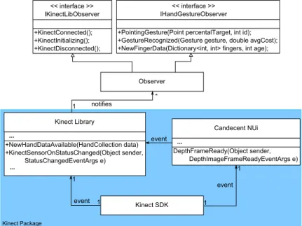
5.1 Structure
TheKinect Packageconsists of three components (cf. Figure 5.1). First, Kinect SDK [Win13b], providing a depth data stream and status information of the Kinect hardware.
Second, Candescent NUI library [Ste13], offering hand and finger position information.
Third, the observable «Kinect Library», providing gesture recognition and a three dimen- sional finger-based input system.
KinectGSDK
<<GinterfaceG>>
IKinectLibObserver 1KinectConnectedwF;
1KinectInitializingwF;
1KinectDisconnectedwF;
<<GinterfaceG>>
IHandGestureObserver 1PointingGesturewPointGpercentalTarget*GintGidF;
1GestureRecognizedwGestureGgesture*GdoubleGavgCostF;
1NewFingerDatawDictionary<int*Gint>Gfingers*GintGageF;
Observer
U U
y
event
event notifies
KinectGLibrary
1NewHandDataAvailablewHandCollectionGdataF 1KinectSensorOnStatusChangedwObjectGsender*
GGGGGGGGGGGStatusChangedEventArgsGeF ...
CandecentGNUi
DepthFrameReadywObjectGsender*G GGGGGGGGGDepthImageFrameReadyEventArgsGeF
...
...
U
U U
event
KinectGPackage
Figure 5.1: «Kinect Library» Components
Kinect SDK is used to get the Kinect sensor’s status information. On change, the Kinect SDK sends an event to the «Kinect Library» which notifies its observers by calling the corresponding method (i.e., KinectConnected, KinectInitializing or Kinect Disconnected). Further, Kinect SDK calls the Candescent NUI’sDepthFrameReady method and informs it about new depth information from sensors of the Kinect. The Candescent NUI library then calculates the hand information (i.e., hand and finger position and vectors) and supplies it to the «Kinect Library». The «Kinect Library»
calculates the gestures and finger information from the consecutive hand information and informs the observers of the «Kinect Library» about the recognized gestures, the amount of fingers on each hand, and where the user is pointing with his finger.
5.2 Microsoft Kinect
5.2 Microsoft Kinect
The Kinect was developed as a toy by Microsoft and was released in 2010. The Kinect has a depth sensor consisting of an infrared projector and an active infra red sensor obtaining depth information regardless of the ambient lighting. Additionally, it has a RGB camera and an array of microphones. The combination of the RGB and the depth camera is called RGB-D camera. The resolution of it is limited to 640x480 with afield of view (FOV) of 43◦vertical and 57◦horizontal. Technically a resolution of 1280x960 with the same FOV is possible but at the cost of frame rate [Win13a]. There are two versions of the Kinect. First,Kinect for Xbox, mainly used for gaming. Second,Kinect for Windows, used for development and supportingnear mode. Near mode is a setting for the depth sensors to focus on tracking closer objects enabling a detection between 0.4 and 0.8m (cf. Figure 5.3) [Cra13]. The area covered in this range is about 90x85x50cm small.
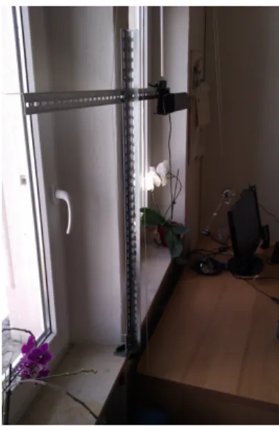
In our use case the Kinect is mounted upside down at a height of about 1 meter so that its cameras point downwards (cf. Figure 5.2). This was done so that the user can brace his elbows on the working surface.
Figure 5.2: Kinect Mounted Upside Down.
5.3 Candescent NUI
TheCandescent NUI (CCT NUI) library is used to calculate the 3D hand information from a raw Kinect depth footage obtained from theMicrosoft KinectSDK [Ste13, Win13b].
Since hand detection requires a high resolution [MPC12] and the library uses the limited resolution of 640x480 pixel, fingers can only be tracked at a range up to 1m. Therefore, Kinect hardware must support the near mode (c.f. Section 5.2, Figure 5.3).
Near M Default ode
0.4 0.8
1
3
4 distance (meters)
regular detection
regular detection
Kinect for Windows
Hand Detection
Figure 5.3: Default vs. Near Mode Hand Detection
To calculate the hand information the CCT NUI library applies a clustering algorithm generating clusters in the depth image. A limited depth range is used preventing cluster detections outside of the working area. After the clustering is done, CCT NUI searches hand and finger patterns in the cluster matrix. Using this method, CCT NUI can not
5.4 Hand Tracking distinguish between a hand and any hand-like objects and, therefore, false positives are possible.
The main advantage of the CCT NUI to other Kinect hand tracking libraries is that the CCT NUI does not require a coping process (i.e., the user does not have to hold his fingers in a certain position until they are detected) so that it can be used on-the-fly.
Further more it does not require any additional hardware (e.g., a CUDA ready NVIDIA graphic card for GPU acceleration) other than the Kinect.
As disadvantage, the library is susceptible to noise and requires a lot of computation power (up to 3.4 GHz) running the clustering algorithm on every depth frame provided by the Kinect RGB-D camera.
5.4 Hand Tracking
This section addresses how the hand data offered by the CCT NUI library is processed in order to obtain viable finger count, position, and direction information.
5.4.1 Finger Count
The CCT NUI library offers finger count information (i.e., how many fingers are visible at a time). However, this information may be very inaccurate depending on several factors like the hands angle, sunlight nuisance and speed of the users hand. Even a slight movement of the tracked hand may result in different amount of fingers detected.
Three steps have been undertaken to improve this detection issue.
Step 1: Fix detection based on the coordinate: Sometimes there are wrong detec- tions in the area below 15 pixels on the y-axis. In Figure 5.4, four fingers (F1-F4) are correctly detected, the fifth finger (F5) is a bad detection. These false detections occur when the user’s arm enters the picture at a certain angle and is partly recognized as a finger. However, it is possible that a recognition in this area is valid, i.e., the user has his