Technische Universität München Fakultät für Informatik
System Development Project (SEP)
Framework and Editor for Malleable Systems
Yuxiang Liang Chuan Tao
Assigner: Prof. Bernd Brügge Ph. D.
Tutor: Korbinian Herrmann
Delivery Date: June 30, 2005
Index of Contents
Part I Introduction
1. Introduction 1.1 General vision 1.2 Domain
1.2.1 General Domain 1.2.2 Asteroids
1.3 Objects, success criteria of the project 2. Existing System
2.1 Visual Programming 2.2 Development environment 2.2.1 Skeleton
2.2.2 HANDS
2.3 Rule-based systems
Part II Requirements on Framework and Editor 3. Proposed System
3.1 Overview
3.2 Functional Requirements 3.2.1 Heterogeneity of Users 3.2.2 Partitions of Users
3.3.3 Corresponding requirements for differentiate user groups 3.3 Pseudo Requirements
4. System Models 4.1 Scenarios
4.2 Use case / Application 4.3 Object Models
4.4 Dynamic Models
Part III System Design and Implement 5 Design Goals and Activities 5.1 Design Goals
5.2 Mapping Subsystem to Processors Components 5.3 Providing Access Control
6. Refactoring and Services
6.1 Refactoring of Asteroids 6.2 Dynamic Models 6.3 Specification of Objects
Part IV Evaluation and Future Work 7. Case Study
8. Future Work
Part V Appendix
A. Acronyms and Abbreviations B. Bibliography
C. Figures index D. Tables index
Part I Introduction
1. Introduction
1.1 General Vision
A frequent criticism on today’s software system is that user are not enough supported when working with the system. The reasons are manifold: on the one hand, sometimes the systems are unusable for end users because of the surplus supplies of functionalities which are not clear arranged. On the other hand, necessary functionalities for users are inadequate. Different approaches attempt to solve it through configuration, macros or script languages.
In order to make applications changeable and customizable, a novel method will be here presented. A malleable system can be dynamically customized and changed after having been deployed. Not only the changes for user interface, e.g. “look and feels”, but also the sequence of the programming, that is the programming logic and fundamental model of application without real programming. Thereby experienced end users or experts are enabled to advance applications individually.
Malleable systems will be applied in the area of mobile computing, for instance: the original functions of mobile phone are now only a minor fraction what mobile phones have nowadays: call. Now man can film, play game, administer appointments and send pictures as message. With the constantly declining hardware price and increasing performance, the trend that always more and more unnecessary functions are integrated into mobile phone. Malleable systems enable the functions to be limited to a minimum once again.
1.2 Domain
1.2.1 General Domain
The work presents a theory with which new application will be developed which are malleable. It focuses on developing new applications which is malleable from the view of users. Users can change, modify and approve functionalities as they desired without too much professional knowledge and know-how in computer science.
1.2.2 Asteroids
Our pilot project is based on existing game Asteroids, so here it is necessary to introduce the game.
The following is the initial interface of the game Asteroids:
Fig.1: Game panorama
Asteroids is a computer-supported game with the above-mentioned user interfaces which include a game board and some functional button which serve as starting points of the modification of the system functionalities to ensure the malleability of the system. The Button is used to start a new game. The button “Edit” on the almost top left corner is the central button to start to change so functions at this system.
On the left side of the picture, you can see the game board including one shuttle and some solid bodies (the number of solid bodies can be accommodated as user desires) after being started which can be smashed into some smaller scraps after being shot.
Some “white fleck” on the background are stars or particles, however they will be
not turned into “solid bodies” in any case, so they will not be the shooting targets of our game player.
On the right side of the interface is some controlling functions, such as left, right, fire rocket, speed up, slow down. And for collision there are not only one options for you, you can choose desired collision strategy which is best suitable for you playing skills and technique and personality or the desire for differentiate variable difficulty levels. “Speed” indicates the current speed of your shuttle which is very important to not only avoid but also shoot solid bodies in the game board. As an option you can also get a new window for games.
1.3 Objects, success criteria of the project
Object is to develop a framework and a tool for manipulation by users: software which is developed using the framework can be acclimatized using of tools by end user.
It should be emphasized, how an application is devised and designed and therewith remains modifiable and extensible dynamically at the runtime. Therefore, the framework presents a real general framework and the editor uses the frameworks classes..
Our work is processed on top of a game named Asteroids which has been taken as an example for supporting and testing the to-be-developed framework and editor which on the one hand bring the game Asteroids into a configurable, modifiable and customizable game, and on the other hand at the same time has been generalized for other systems, such as player etc.
2. Existing System
2.1 Visual Programming
Visual C# . NET
„Visual C# .NET is the modern, innovative programming language and tool for building .NET-connected software for Microsoft Windows®, the Web, and a wide range of devices. With syntax that resembles C++, a flexible integrated development environment (IDE), and the capability to build solutions across a variety of platforms and devices, Visual C# .NET significantly eases the development of .NET-connected software. [1]
Microsoft Visual C# .NET is the comprehensive toolset for creating XML Web services and Microsoft .NET—connected applications for Microsoft Windows® and the Web. [1]
This robust development package, which uses the component-oriented C#
development language, offers beginning and intermediate developers with C++ or Java experience a modern language and environment for creating next-generation software. Visual C# .NET delivers superior functionality for streamlining business processes, including:
• Rapid design, development, and deployment support for creating and consuming Web services.
• Form designers and visual controls for creating rich Windows-based applications.
• Authoring tools and services for building powerful Microsoft .NET server-based solutions.
• Migration tools for converting Java-based projects to the Microsoft .NET development environment.
With Visual C# .NET , developers can build solutions for the broadest range of clients, including Windows, the Web, and mobile or embedded devices. Using this elegant programming language and tool, developers can leverage their existing C++
and Java-language skills and knowledge to be successful in the .NET environment.
“[1]
2.2 Development Environment 2.2.1 Skeleton
“Skeleton is a visual scripting environment as an extension of Squeak etoy [2] with Connectors [3] system to make mathematical and physical simulation for non professional computer user. Squeak etoy system is a unique attempt to provide effective way of programming for children in learning environment. Skeleton makes logical relationships among graphical objects in the etoy system with spreadsheets-style interface, and users can describe object’s behavior in declarative representation.
Concreteness is one of the key words of end user scripting. Direct manipulation of objects on the screen is helpful to understand what happened in your computer.
Skeleton’s spreadsheets style interface realizes this concreteness to show any input and output data same time.
Sometime user scripting system like etoy has a problem of modularity. This aspect is important as a basis of reusing, thus Skeleton has some features for reusing. Tree structured naming system like ECMAScipt [4] is used to access to Skeleton object by name. And modularity is realized by sheet-card mechanism that is possible to reuse a behavior of objects in another context in Skeleton.
User interface:
This section is described about user interface of Skeleton using a geometric example borrowed from ThingLab [5]. This example is to demonstrate a geometric theorem, which states given an arbitrary quadrilateral, if one bisects each of the sides and draws lines between the adjacent midpoints, the new lines form a parallelogram.
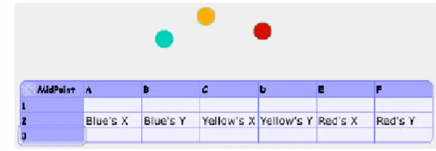
Fig. 2: Skeleton sheets and morphic points
Morphic is basic graphical object system in Squeak. User can manipulate morphs by mouse operation directly, or by tile scripts with slots of the morph. Skeleton has capability dealing with these morphic slots. Now we pick up a Skeleton sheet and three points on the screen from “supply flap”. Then we write object’s name on the sheet as labels like “Blue’s X, Blue’s Y …”
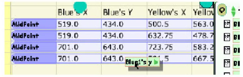
Fig. 3: drop a slot of morph to cell
Fig. 4 Attached cells
Using drag-and-drop, a slot of morph can be connected with a sheet’s cell. We attach each x-y coordinate of point into cells.
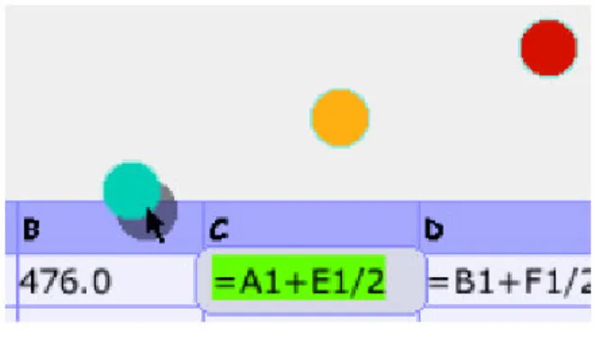
Fig. 5: formula keeps midpoint
When we put a formula in an attached cell, related morph is moved by the formula.
In this case, “= A1 + E1 / 2” means “yellow’s x = (blue’s x + red’s x) / 2” (in Smalltalk syntax, all binary operators have same priority). The formula is used to calculate coordinate of midpoint of blue and red. As ordinary spreadsheets, first character ‘=’ in cell is indicated as formula.
Fig. 6: card made from sheet
Formulas on top row of the sheet have special meaning. These formulas can be reused on other sheets as card. A card is made by dragging change-size halo to become the sheet small.
Fig. 7: embedded card in other sheet
Card can be embedded any sheet. Four copies of the card are made and put into new sheet named “QTheorem”.
Fig.7: attaching other slot to card
After all cards are assigned with more morphic objects and joining by Connectors’ [3]
line. The project can show a quadrilateral theorem.
Fig. 8: demonstrate theorem Basic feature:
Skeleton has basic functions of spreadsheet. Like commercial spreadsheets, it has matrix includes cells with formulas. To describe a formula, Skeleton uses mix syntax of Excel-like expression and normal Smalltalk expression. Each cell is pointed as
‘A1’ style position or user defined string name. Any numbers, strings or Smalltalk objects are stored in cells. Additionally, etoy’s slots can be attached with cells, and any morphs are controlled by Skeleton.
Relative reference and listing reference of cells is not supported. For this purpose, card mechanism is used for reusing formula. After user makes a formula in a spreadsheet, the user can reuse the formula to make its card from the spreadsheet.
The relationship among card and spreadsheets (sheet) is similar to instance and class in object oriented concepts.
Some predefined library cards are provided. They include mathematical function like sum and average. Name is used for specifying these library cards. User defined named cells, sheet, and library cards are in same name space, and the system bounds their name using same mechanism. A formula can use the name with tree structured path to search these names.
Architecture:
One of the most important requirements of Skeleton was flexibility. Skeleton is not stand-alone system, yet it needs to connect to existing etoy’s base system, and needs various kind of ability to make interesting application. So Skeleton consists of several parts for this requirement.
Kernel and library:
Kernel provides basic services include handling spreadsheets-style interface and naming protocol. But any concrete data storage and computation is not included.
Kernel defines just how an object shows and what name is the object. Therefore any different data structure and
updating strategy can be mixed. This is because to suppose to be written various logical primitive library as building block for specific demand. Skeleton’s standard spreadsheet
SkSheet is just one of the libraries.
Programming Style:
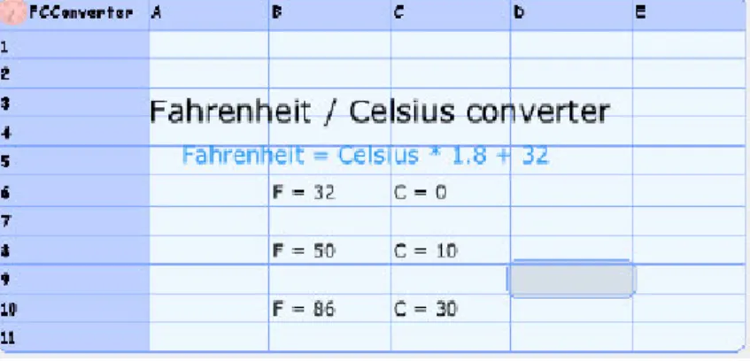
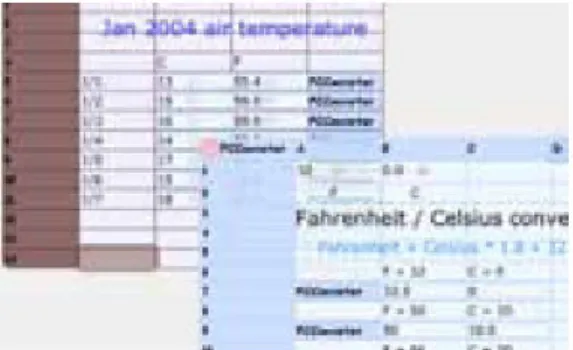
Code reading is regarded as an important issue. Once a program is written, the code comes out and is read by other people widely. Despite reading code is harder than writing code, much effort must be gone for maintenance code after developed. The concrete oriented scripting style of Skeleton helps writing code as readable documentation. Using common example of “Fahrenheit / Celsius unit converter” that is also in ThingLab, we describe a typical programming style for example in Skeleton.
Fig. 9: Describe specification
First, to make sure what the code is, some documentation and examples are written the sheet. These examples show how the code does in concrete form.
Fig. 10: writing code the top of sheet
Along the specification, we write codes on top row of the sheet.
Fig. 11: embed card into itself
When the code is complete, we can make a card of the sheet, and embed the card into original sheet itself. The card is used to test if the code satisfies given specification, and used as live documentation for someone or yourself in future.
Fig. 12: using on other sheet
The Skeleton system provides simple and flexible extension of Squeak etoy system.
It controls any etoy’s object with easy spreadsheet style interface. The spreadsheet has abundant ability to use dynamic nature of Smalltalk directly, and has modularity with card system.
2.2.2 HANDS
HANDS, a new programming system for children that focuses on usability, where HCI knowledge, principles, and methods guided all design decisions. The features of HANDS are presented along with their motivations from prior empirical research on programmers and new studies conducted by the authors. HANDS is an event-based language that features a concrete model for computation, provides operators that match the way non-programmers express problem solutions, and includes domain-specific features for the creation of interactive animations and simulations.
In user tests, children using HANDS performed significantly better than children using a reduced-feature version of the system where more traditional methods were required to solve tasks.
The programming environment comprises the tools for viewing, editing, debugging and running the program. Many programming languages are designed independently from the environment, but the HANDS language was not. We designed the environment to work in tandem with the language to address some important usability issues. For example, editing support can relieve many of the problems that people have with writing programs in a textual language. The environment’s components play critical roles in the overall usability of the HANDS system.
One of the first decisions we faced was whether the language should be textual or
visual. In visual languages, graphics replace some or all of the text in specifying programs. Proponents of visual programming languages often argue that reducing or eliminating the text in programming will improve usability [6]. However, much of the underlying rationale for this expectation is suspect [7]. User studies have shown mixed results on the superiority of visual languages over text (e.g. [8]), and the advantage of visual languages tends to diminish on larger tasks.
The participants usually drew pictures describing the layout of the program, and then used text to describe the behaviors and actions. HANDS supports this hybrid approach, and relies on the programming environment to alleviate some of the difficulties of textual languages. During program entry, context-sensitive menus make it easier to know what choices are available and to enter the program correctly.
This support could be augmented with a tile-based editor, as seen in Squeak [9] and other systems. Also, the system could provide visual representations for textual elements that are difficult. One example is Boolean expressions, as discussed below.
Representation of the program:
The von Neumann computational model is an obstacle for beginners because it is unfamiliar and has no real-world counterpart [10]. Beginners must learn, for example, that the program follows special rules of control flow for procedure calls and returns.
Usability could be improved by providing a different model for the computation that is concrete and familiar [6].
Most languages also have complex rules that govern the lifetimes of variables and their scopes. Variables may not exist at all when the program is not running, and during execution they are usually invisible, forcing the programmer to use print statements or debuggers to inspect them. This violates the principle of visibility, and contributes to a general problem of memory overload [11]. The programming system should make information visible or readily accessible any time it is relevant.
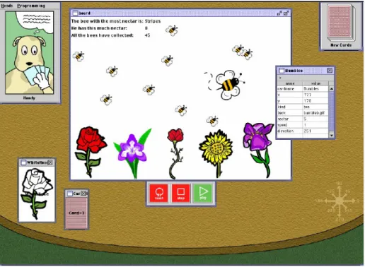
The HANDS system addresses these problems with a new model of computation that is concrete, uses familiar concepts, and has high visibility. In HANDS, an agent named Handy sits at a table, manipulating information on cards (see Figure 1). All of the data in the system is stored on these cards, which are global, persistent and visible on the table. Each card must have a unique name, which is not case sensitive.
There are no local variables, although a temporary naming mechanism is available
(see Section 4.12).
Fig. 13: User Interface
The HANDS system portrays the components of a program on a round table. All data is stored on cards, which can be drawn from the pile at the top right and dragged into position. At the lower left, two cards are shown face-down on the table. One has a generic card back and the other has been given a picture by the programmer. In the center of the table is a board, where the cards are displayed in a special way where only the contents of the back are displayed. Each picture, string, and number on the board is a card. At the right, one of the cards has been flipped face-up, where its properties can be viewed and edited. The programmer inserts code into Handy’s thought bubble, by clicking on Handy’s picture in the upper left corner. When the play button is pressed, Handy begins responding to events by manipulating cards according to the instructions in the thought bubble. The stop button halts the program, and the reset button will restore all cards to their state at the time the play button was last pressed. For reference, a compass is embossed on the table at the lower right.
Programming style and model of execution:
HANDS is event-based, to match the style of programming that we observed in our studies. A program is a collection of event handlers that are automatically called by
the system when a matching event occurs. Inside an event handler, the programmer inserts one or more imperative statements to execute in response to the event. After these statements have executed, control returns to the system, where the next event is dispatched. Event handlers can be triggered by the following kinds of events: the program starting to run or stopping; an object appearing, disappearing, or changing;
objects colliding; objects being clicked by the user; keystrokes; nothing happening (the idle loop); or something happening (any event). If an event is generated and there is no handler for it, the system continues on to the next event in the queue.
Figure 2 shows the browser for event handlers.”[15]
2.3 Rule-based Systems
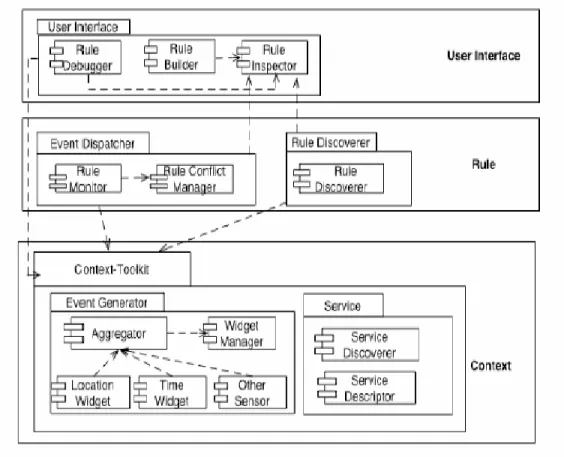
Tao Zhang has advised a three-tier architecture for rule-based system which is concerned with end-user programming and modification of context-aware application behavior using a rule-based approach to building context-aware applications, which separates context collection, distribution from rule-based inference that controls application behavior [12].
While the software developers are primarily responsible for the context layer and rule layer, end-users use a graphical user interface to modify and control the (almost) overall system behavior. [12]
Fig. 14: Three-tier architecture for context-aware systems
“In the architecture shown in figure 14, the context-toolkit is selected, a framework developed by Dey [13], which separates the acquisition and representation of context from the delivery and reaction to sensor context by a context-aware application, as our low-level communication infrastructure.”[12]
“To evaluate the approach, different prototypes have been realized such as the component of the rule tier responsible for rule conflict management, as well as the user interface responsible for defining rules.
- Use JESS for the Rule Layer
- User Interface Prototypes for defining personal rules” [12]
Advantages:
- differentiate context collection, distribution from rule-based inference controling application behaviour
- differentiate the acquisition and representation of context from the delivery and
reaction to sensor context - Use JESS for the Rule Layer
“The advantages of JESS are the following:
(1) JESS consists of a rule specification language that can be used to define ECA rules.
(2) JESS works well with the context-toolkit, since both are implemented in Java.
(3) Low-level rule conflict resolution strategies are by default integrated in JESS.
While the end-users define the priority of the rules, JESS is responsible for triggering rules in the right order at runtime.” [12]
Disadvantages:
- Evaluation work with non-computer scientists is not finished and no result to be interpreted
Part II Requirements on Framework and
Editor
3. Proposed System
3.1 Overview
By means of the framework and tools an end user can execute changes of an application built with the aid of the framework. This could be extended on the one hand to the exterior appearance and on the other hand to the control flow and the behavior. Furthermore the underlying model of an application should be adaptable.
3.2 Functional Requirements 3.2.1 Heterogeneity of users
As we know, neither do all users have identical understanding, knowledge, know-how, and competence nor do they function in the same way. So when the functional requirements are taken into account, it must be admitted that the heterogeneity of their behaviors of taking advantage of the malleable system have to be deliberated carefully. In this case, users are to be grouped into several different categories.
In order to explain the special application concepts to the end users, the system developer prepares materials to support them to execute modifications. In doing so, they can resort to the library of general display formats which can be used for modification.
3.2.2 Partitions of users
- Layman, who has been educated/trained to be neither programmer nor a specialist in the relevant area or just with very limited knowledge.
- Expert, who has been normally educated in the relevant area, however does not have so much know-how in programming.
- Programmer, who has been trained to be a professional in programming, nevertheless not a specialist in the relevant area.
3.2.3 Corresponding requirements for differentiate user groups
Important is, during the program development, the implementation programmer determines which parts are modifiable by which layman, expert and programmer.
Doing this could not only prevent security-critical or especially complex parts from being modified, but also grant old systems to integrate.
Different users have different understanding of the system, namely different level of mastering the modification of the system. In this context, modifications are differentiated between application and structure.
Here you can take a look of the following table which describes the situation for each user group.
In the table:
- „Application“ means color, music, control keys, number, speed or something like that. According to this point it is to be decided whether applications can be changed by different users which is rather primary purpose of this system. In this case, all uses are allowed to change applications in accordance with predefined structures.
- “Structure” - changing structure means not just modifying some “superficial”
things about the system, but some radical and in-depth framework, formation, design and structuring on which applications are established. Here, only programmer is supposed to have the capability to conduct changes on system structure without too much mistakes or side effect, while other two user groups, namely, layman and expert are usually not encouraged to take these actions.
- “Details” means how much details should be offered to each user groups. In order to protect the layman from too many details, the program context should be used as far as possible. This means that, the context should be determined at the time of the change in an edit mode – concretely, only instructions or results which are just available in the actual state of the program should be presented. Reversely, knowing details would be pretty positive for programmer who not only wants to conduct their desired modifications more smoothly but also sometimes can discover new
technological progress and advancement with being given instantaneous inspiration which can be applied at the system itself and some other projects which is one of the most important factors to let computer science continuously get ahead as a snowball in any case. In the middle of layman and programmer is expert. Although they have much knowledge about their specialty, they usually have not so much programming know-how, particular in technological details, whereas some of them are programmer or “semiprogrammer”. For this users group, whether they should be provided details depends on their programming skills.
- For the “visibility” of the user interface: general visibility is also one of the main purpose of a malleable system, however for programmers it is allowed there are some “invisible” interface which would not be great barrier for programmer who pursue technological details and improvement.
Application Structure Many details Visibility
Layman yes No no yes
Expert yes No Yes / no yes
Programmer yes yes yes Not necessary
Tab.1: Corresponding situation for differentiated user groups
Corresponding requirements for differentiate user groups [14]
- Usability is “the ease with which a user can learn to operate, prepare inputs for, and interpret outputs of a system or component. Usability requirements include, for example, conventions adopted by the user interface, the scope of online help, and the level of user documentation. Often, clients address usability issues by requiring the developer to follow user interface guidelines on color schemes, logos, and fonts.” [14]
At a malleable system the usability is “involuntary” optimized with self-explanatory functional button and edit interface, therefore usability is high.
- Reliability is “the ability of a system or component to perform its required functions under stated conditions for a specified period of time. Reliability requirements include, for example, an acceptable mean time to failure and the
A malleable system and its component can perform predefined functionalities within specified period of time, therefore reliability is high.
- Performance requirements are “concerned with quantifiable attributes of the system such as response time(how quickly the system reacts to a user input), throughput(how much work the system can accomplish within a specified amount of time), availability(the degree to which a system or component is operational and accessible when required for use) and accuracy.” [14]
As a malleable system without other specification, the performance is not especially high.
- Supportability requirements are “concerned with the case of changes to the system after deployment, including for example, adaptability (the ability to change the system to deal with additional application domain concepts), maintainability (the ability to change the system to deal with new technology or to fix defects), and internationalization (the ability to change the system to deal with additional international conventions, such as languages, units and number formats). The ISO 9126 standard on software quality [ISO Std. 9126], similar to the FURPS+ (Functional, Usability, Reliability, Performance, and Supportability) model, replaces this category with two categories: maintainability and portability (the ease with which a system or component can be transformed from one hardware or software environment to another).” [14]
The chapter 5 follows from this.
3.3 Pseudo Requirement
“The FURPS+ model provides additional categories of requirements typically also included under the general label of nonfunctional requirements:
- Programming language has to be chosen very carefully, because it is related with reliability, performance, adaptability and maintainability, some of which are
not improvable after a programming language is chosen. Some programming languages are independent on platform, that is to say, with these language, a system can be developed and improved on any platform without too much endeavour of caring the differentiation and mistakes occurred by “transportation”
from one platform to another.”[14]
Our malleable system is developed with Java which is a platform-free programming language and it easy usability have been coming to light since many years.
- Interface requirements are “constraints imposed by external systems, including legacy systems and interchange formats. “[14]
The programming language which is used at our malleable system is Java which with perfect interface which can be easily connected with external system including legacy and interchange implications.
4 System Models
4.1 Scenarios
Name: Asteroids: ControlKeyChange
Participants: initiated by Fred
Flow of events: 3. Fred clicks the edit button 4. The „Key“ – event shows up
5. Fred chooses the presentation “Change”
6. The system provides Fred with different kinds of presentations.
7. Fred chooses key presentation
8. Fred chooses certain keys-combination for the presentation 9. Fred chooses “Complete”
10. The system saves the changes.
Exceptions: - Particular requirements: -
Name: Asteroids: SolidBodySizeChange
Participants: initiated by Fred
Flow of events: 3. Fred clicks the edit button
4. The „SolidBody “ – event shows up 5. Fred chooses the presentation “Change”
6. The system provides Fred with different kinds of presentations
7. Fred chooses SolidBodySize presentation
8. Fred chooses new sizes (diameter in centimetre)of solid
bodies for the presentation 11. Fred chooses “Complete”
12. The system saves the changes.
Exceptions: -
Particular requirements: -
Name: Asteroids: SolidbodySpeedChange
Participants: initiated by Fred
Flow of events: 3. Fred clicks the edit button 4. The „Speed “ – event shows up
5. Fred chooses the presentation “Change”
6. The system provides Fred with different kinds of presentations
7. Fred chooses Speed or Acceleration presentation
8. Fred chooses new parameters of the speed or acceleration of solid bodies for presentation
9. Fred chooses “Complete”
10. The system saves the changes.
Exceptions: -
Particular requirements: -
Name: Asteroids: SolidbodyNumberChange Participants: initiated by Fred
Flow of events: 3. Fred clicks the edit button
4. The „ SolidBody“ – event shows up 5. Fred chooses the presentation “Change”
6. The system provides Fred with different kinds of presentations
7. Fred chooses SolidBodyNumber presentation 8. Fred chooses the number of solid bodies for the
presentation
9. Fred chooses “Complete”
10. The system saves the changes.
Exceptions: -
Name: Asteroids: YouLostDialogChange
Participants: initiated by Fred
Flow of events: 3. Fred clicks the edit button
4. The „You Lost“ – event shows up
5. Fred chooses the presentation “Change”
6. The system provides Fred with different kinds of presentations.
7. Fred chooses sound presentation
8. Fred chooses certain sound for the presentation 9. Fred chooses “Complete”
10. The system saves the changes.
Exceptions: -
Particular requirements: -
Name: Asteroids: GameMusicChange
Participants: initiated by Fred
Flow of events: 3. Fred clicks the edit button 4. The „ Music“ – event shows up
5. Fred chooses the presentation “Change”
6. The system provides Fred with different kinds of presentations
7. Fred chooses GameMusic presentation 8. Fred chooses certain music for the presentation 9. Fred chooses “Complete”
10. The system saves the changes.
Exceptions: -
Particular requirements: -
Name: Asteroids: Start
Participants: initiated by Fred
Flow of events: 3. Fred clicks the edit button 4. All events shows up
5. Fred chooses the presentation “YouLost” and “Change”
6. Fred chooses adding commands 7. Fred chooses the command “Start”
8. Fred chooses “Complete”
9. The system saves the changes.
Exceptions: -
Particular requirements: -
Name: Asteroids: Stop
Participants: initiated by Fred
Flow of events: 3. Fred clicks the edit button 4. All events shows up
5. Fred chooses the presentation “YouLost” and “Change”
6. Fred chooses adding commands 7. Fred chooses the command “Stop”
8. Fred chooses “Complete”
9. The system saves the changes.
Exceptions: -
Particular requirements: -
4.2 Use case / Application
Name: ControlKeyChange
Participants: initiated by Player
Entry condition: 1. Before Fred plays Asteroids or when Fred is playing Asteroids, the Control keys can be reconfigured 2. Asteroids is developed as a malleable system.
Flow of events: 1. Player clicks the edit button
2. System presents “Key”- Event 3. Player chooses the presentation “Change”
4. System provides Player with different kinds
of Player with different kinds of
presentations.
5. Player chooses Key presentation
6. System provides all kinds of Key presentations.
7. Player chooses certain keys-combination for the presentation and chooses complete
8. System saves the changes.
Exit condition: when Fred starts a new game or continues one game, the chosen key-combination can be brought into usage.
Particular requirements: -
Name: SolidBodySizeChange
Participants: initiated by Player
Entry condition: 1. Before Fred plays Asteroids, the size of solid bodies can be changed.
2. Asteroids is developed as a malleable system.
Flow of events: 1. Player clicks the edit button
2. System presents “SolidBody” event.
3. Player chooses the presentation “Change”
4. System provides Player with all kinds of presentation
5. Player chooses SolidBodySize presentation
6. System provides all kinds of presentations 7. Player chooses certain sizes and click “Complete”
8. System saves the changes.
Exit condition: After Fred loses the next play, the chosen sound is played. The
next play
can be started by clicking the “Start” button.
Particular requirements: -
Name: SolidbodySpeedChange
Participants: initiated by Player
Entry condition: 1. Before Fred plays Asteroids or when Fred is playing Asteroids, the speed and the acceleration of solid bodies can be changed.
2. Asteroids is developed as a malleable system.
Flow of events: 1. Player clicks the edit button
2. System presents “Speed” event 3. Player chooses the presentation “Change”
4. System provides Player with different kinds of presentations
5. Player chooses Speed or Acceleration presentation 6. System presents all kinds of presentations 7. Player chooses new parameters of the speed or
acceleration of solid bodies for presentation and chooses
“Complete”
8. The system saves the changes.
Exit condition: After changing the speed or acceleration, Fred can play the game with new speed or acceleration as specified.
Particular requirements: -
Name: Asteroids: GameMusicChange
Participants: initiated by Player
Entry condition: 1. Fred is playing Asteroids, at the same time the game music can be Changed or selected.
2. Asteroids is developed as a malleable system.
Flow of events: 1. Player clicks the edit button
2. Systempresents „Music“ event 3. Player chooses the presentation “Change”
4. System provides Player with different kinds of presentations
5. Player chooses GameMusic presentation
6. System provides all kinds of presentations 7. Player chooses certain music for the presentation and
“Complete”
8. The system saves the changes.
Exit condition: After Fred loses the next play, the chosen sound is played. The next play can be started by clicking the “Start” button.
Particular requirements: -
4.3 Object Models
Presentations for Events: Every event can have one or more form(s) of presentation.
A command can be alternatively applied for the presentation of a event, for example, command: PlayMusic. This results in that, very many commands must be created and applied.
Presentations are description for certain elements and it must not be graphical.
Example for presentation are IconView for presenting icon, sound presentation for text output, JavaView for showing source text or noView which presents nothing. It
must be specified where the presentations should appear.
Application state: Differences can be changes at model, behaviors and user interfaces. It must be kept in mind that the changes do not apply for all thinkable states of a task. Crtain presentation forms are only visible in some states, e.g. just after an arrival of an event. Similarly, the number of available commands depends on the state.
Events: For the existing system events, information about time or the click on a key, application domain application are imported which indicate important points in the application. An example for application domain events is Asteroids.
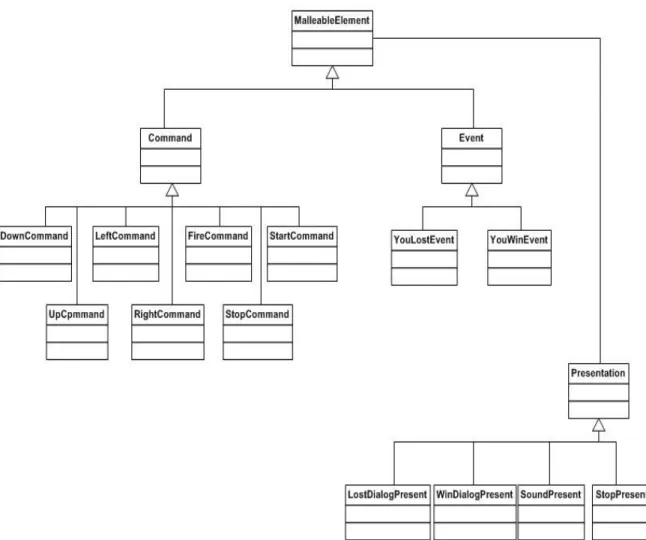
Class diagram of Framework:
Fig. 15: Class diagram of Framework
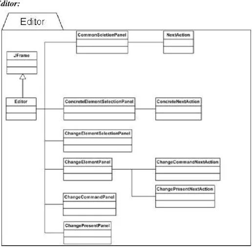
Class diagram of Editor:
Fig. 16: Class diagram of Editor
An Example imposing the inherent conducting situation between the editor and framework is here introduced with using three diagrams:
The example focuses on the changing presentation after failure. Before changes there is a dialog window which indicates that the player fails and after changes there is a sound instead of dialog window.
Fig.: 17: before changes after failures
Fig.18: Procedures for changes
Fig. 19: after changes
Part III System Design and Implementation
5. System Design
5.1 Design Goals
The definitions of design goals are differentiated and so it is very important to project development. In light of Prof. Brügge’s definition:
“It identifies the qualities that our system should focus on, Many designs can be inferred from the nonfunctional requirements or from the application domain. Others will have to be elicited from the client.” [14]
Our project should focus on the malleability and hereon related objects. For example, our project have to have high modifiability, adaptability, readability, traceability of requirements, utility and usability and therefore low deployment cost, upgrade cost, maintenance cost and administration cost. However the performance of our project should not be exacted to high throughput or huge memory. As to reliability, security and safety, although our project does not emphasizes it extremely, the three criteria are always suitable for each software project.
5.2 Mapping Subsystem to Processors and Components
“Many Systems run on more than one computer and depend on access to an intranet or to the Internet. The use of multiple computers can address high-performance needs and interconnect multiple distribute users. Consequently, we need to examine carefully the allocation of subsystems to computers and the design of the infrastructure for supporting communication between subsystems. These computers are modeled as nodes in UML deployment diagrams. Because the hardware mapping activity has significant impact on the performance and complexity of the system, we perform it early in system design. “[14]
In this chapter will be demonstrated:
Deployment Diagram for the system:
Here, dashed arrows represent the dependences between components, such as, Editor, Framework, Presentation and Malleable elements.
Fig.20: Deployment diagram for the system Framework:
Fig.21: Framework
Editor:
Fig.22: Editor
Editor – Framework:
Fig. 23: Editor and Framework
For the aspects of hardware, there should be no problem, because all development and implementation are conducted on the same computer.
5.3 Providing Access Control
“In multi-user systems, different actors have access to different functionality and data.
For example, an everyday actor may only access the data it creates, whereas a system administrator actor my have unlimited access to system data and to other users’
data.” [14]
In the case of our project, there is no differentiated/discriminated types of access, there is only one, i.e. every user may play the game, conduct the behavior in their convenience with their desired mode allowed by the functionality. However there are suggestions which could be suitable for which users, e.g. layman users are not exhibited from reading technological details, but are suggested not doing so without external help from professionals.
6 Refactoring and Services
6.1 Refactoring of Asteroids
The old Asteroids put many commands, such as, speedDown, speedUp, turnLeft, turnRight and fireRocket in the same file SpaceShuttleController, while startCommand and stopCommand are put into the file ToolBar. The two events YouLost, YouWin and Presentation are put into the file Referee.
The old Asteroids have to be reconstructed, because:
On the one hand, the structure of the old program is not clear at a glance to some extend which can mistake somebody else. On the other hand, the old structure prevent people from changing, modifying and improving the system as they desire.
The easily-realizable malleability is absolutely our main purpose for the project to implement and our project serves as a pilot project in this meaning.
Thus, in the new developed framework, all commands, events and presentation are separated into three different sub-packages which belong together to a father-package, namely org.globalse.malleable.framework. After doing so, the malleable of new system is radically improved. In org.globalse.malleable.framework there are Command.java, Event.java and Presentation.java which are correspondingly the frameworks of org.globalse.oose.asteroids.control.command, org.globalse.oose.
asteroids.control.events and org.globalse.oose.presentations in which files are responsible for realizing and implementing the functionalities and requirements.
Fig.24: class diagram for Asteroids
6.2 Dynamic Models
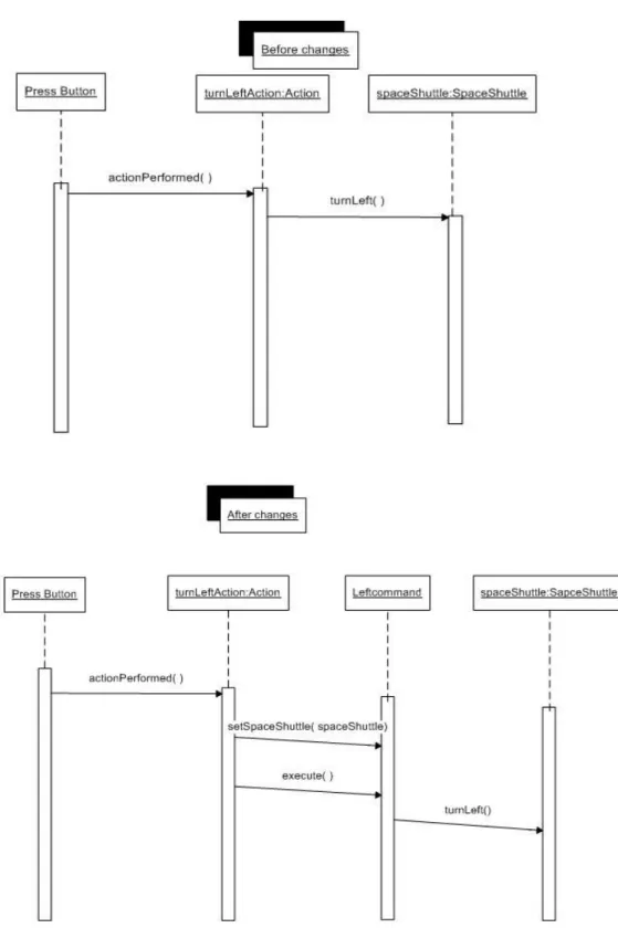
TurnLeft:
Fig. 25: Sequence diagram for „TurnLeft“
After changes, turning left does not function with out setSpaceShuttle(spaceshuttle)
TurnRight:
Fig.26: Sequence diagram for „TurnRight“
After changes, turning right does not carry out, unless setSpaceShullte(spaceShuttle) and execute() function at first.
SpeedUp:
Fig.27: Sequence diagram for „SpeedUp“
After changes, the function IncrementSpeed can not realized without
SpeedDown:
Fig. 28: Sequence diagram for „SpeedDown“
After changes, the method decredmentSpeed can not realized without setSpaceShuttle(spaceShuttle) and execute() through Downcommand.
Fire:
Fig. 29: Sequence diagram for „Fire“
After changes, firing does not function directly any more, but through FireCommand
YouLost:
Fig.30: Sequence diagram for „YouLost“
After changes, instead of JOptionPane, YouLostEvent, Presentation and DialogPresent are used to support the new implementation together with show() and showMessageDialog.
YouWin:
Fig.31:: Sequence diagram for „YouWin“
After changes, instead of JoptionPane, YouLostEvent, Presentation and dialogPresent are taken together with Present(), show() and showMessageDialog().
6.3 Specification of Objects
Package:
Class:
Method:
Package:
Class:
Method:
Class:
Method:
Class: !
Method: !
!
" !
# $ "
Class:
Method: "
Package:
Class:
Method: # $
Package:
Class: !
Method: !
!
!
" !
Class:
Method:
%
Class: !
Method: !
!
!
& " !
Class: !
Method: !
!
" !
# $
Package:
Class:
Method:
%
Class: !
Method: !
!
" !
# $
Class: &
Method: '(
&
Package:
Class:
Method: # $
Package:
Class: ) $
Method: ) $
$ "
Part IV Evaluation and Future Work
7. Case Study
YouWin case Study:
Fig. 32: You-win (with dialogue)
When a player wins, then the you-win dialogue with the time how long the game lasts will show up automatically. Here “win” means all the solid bodies and their possible scraps have been shot and disappeared before the shuttle is collided with any of them.
When a player do not want to see the You-win dialogue after each triumph from visual and even motivational reasons, instead, he can hear music which can be selected from predefined music-repository by the developer. For this purpose, he should at first click the Edit button, then the edit dialogue is showed as follows:
Fig. 33: Editor
With Editor, predefined options of both Event and Command are showed at the right pane in the dialogue.
Fig. 34: Editor, after an „Event“ being selected
For the change of music, “Event” should be here selected and then “next” turns up.
Then you can continue your modification at the next steps by clicking the button
“next”.
Fig. 35: list of possible events
In order to change the presentation, you have to choose a concrete event from the list of events at first.
Fig. 36: An Event is selected
Here YouWinEvent is selected and clicking the button “Next” leads to next step.
Fig. 37: Change presentation and Append command
There are two options: change presentation and append command. For our specified purpose, change presentation is selected.
Fig.38: List of presentations At this Step, one certain presentation is to be selected.
Fig. 39: A predefined presentation of the presentation list is chosen.
The presentation “SoundPresent” is selected
Fig.40: Save the change
After the presentation has been selected, system saves the change.
Fig.41: Music instead of „You-win“ dialogue
Now after winning the game, you do not see the You-win dialogue any more, instead of this, a selected music will accompany you for a short period of time.
8. Future Work
When we take a future-oriented view for malleable system and related research, development and applications in our to each other increasingly nearing and networked Earth-components which could be countries, regions, universities, persons and hereon based derivatives, it is not difficult to find that the improvement and applications of malleable technologies and related and hereon-developed is realizable which match a higher level of usage in life, working, communication little by little which is considered the basis of a so-called “holistic” information society for the first time of the history of human being as we know.
The further development and application can be extended to following domains:
8.1 Manufacturing
At first, the domain of manufacturing is emphasized in the future objectives of malleable systems. For example, company A bought modern product line with embedded IT-based control system which not only serves as for the current production but also for new productions in the future from company B.
On the one hand the manufacturing flows including many predefined flow-components can be reconstructed in order to form semi-new or brand-new flows contributing to an end-product or semi-product. This process can be conducted by company A by themselves after the initial buying which is different from the next case.
On the other hand, in the relatively far future, not only applications f the embedded control system are reconstructive, but the structures of the system can also be modifiable, improvable and even creatable which is adaptable to the new situation of holistically production. However at the level of structure changing, company A would have to buy new components from company B – much better than buy a fire-new production system from the view of reducing manufacturing floor area, saving costs for intruding new equipment, sparing familiarization time and environment-friendship.
8.2 Smart house
Smart house is a relatively new conceptualization as a result of the increasingly developed information technologies and the more extended pursues after modern life at home. In this case, all kinds of embedded administrating system which are installed in different house equipments arise at a certain percent of families. In the meaning, malleable system is the best option, because in most case, a family cannot foresee all possible equipment on which embedded control system should be installed. Malleable system can be extended component-wise, so it is the best option for the families.
As for traffic control system and finance and accounting services there are similar synergy from malleable systems and the corresponding domains.
Part V Appendix
A. Acronyms and abbreviations
FURPS+: Functional, Usability, Reliability, Performance, and
Supportability. The + indicates the additional subcategories.
B. Bibliography
[1] www.microsoft.com [2] http://www.squeakland.org
[3] Connectors http://nedkonz.dhs.org:8080/Ned/8
[4] http://www.ecma-international.org/publications/standards/Ecma-262.htm
[5] D. Ingalls, S. Wallace, Yu-Ying Chow, F. Ludolph and K. Doyle,“`Fabrik: a visual programming environment” 1988
[6] D. C. Smith, A. Cypher, and J. Spohrer, "KidSim: Programming Agents Without a Programming Language,"
Communications of the ACM , vol. 37, pp. 54-67, 1994.
[7] A. F. Blackwell, "Metacognitive Theories of Visual Programming: What Do We Think We Are Doing?," in Proceedings of the VL'96 IEEE Symposium on Visual Languages . Boulder, CO: IEEE Computer Society Press, 1996, pp.
240-246.
[8] T. R. G. Green and M. Petre, "When Visual Programs are Harder to Read than Textual Programs," in Human-Computer Interaction: Tasks and Organisation, Proceedings of ECCE- 6 (6th European Conference on Cognitive Ergonomics), G. C. van der Veer, M. J. Tauber, S. Bagnarola, and M. Antavolits, Eds. Rome:
CUD, 1992.
[9] J. Steinmetz, "Computers and Squeak as Environments for Learning," in Squeak:
Open Personal Computing and Multimedia , M. Guzdial and K. Rose, Eds.:
Prentice Hall, 2001, pp. 453-482.
[10] K. Kahn, "ToonTalk: An Animated Programming Environment for Children,"
Journal of Visual Languages and Computing , vol. 7, pp. 197-217, 1996.
[11] A. Repenning and T. Sumner, "Agentsheets: A Medium for Creating Domain-Oriented Visual Languages," Computer , vol. 28, pp. 17-25, 1995.
[12] Zhang, T., An Architecture for Building Customizable Context-Aware Applications by End-Users, Pervasive 2004 Doctoral colloquium.
[13] Dey, A.K. et al. A conceptual framework and a toolkit for supporting the rapid prototyping of context-aware applications. HCI Journal 16(2-4), 2001, 97-166.
[14] B. Brügge and D. Allen. H, „Object-Oriented software Engineering – Using UML, Patterns, and Java“, Pearso Education International, 2nd edition, 2004 [15] T. Yamamiya, Skeleton-2004-01-02, 2004
C. Figures index
Fig.1: Game panorama
Fig. 2: Skeleton sheets and morphic points Fig. 3: drop a slot of morph to cell
Fig. 4 Attached cells
Fig. 5: formula keeps midpoint Fig. 6: card made from sheet Fig. 7: attaching other slot to card Fig. 8: demonstrate theorem Fig. 9: Describe specification
Fig. 10: writing code the top of sheet Fig. 11: embed card into itself Fig. 12: using on other sheet Fig. 13: User Interface
Fig. 14: Three-tier architecture for context-aware systems Fig. 15: Class diagram of Framework
Fig. 16: Class diagram of Editor Fig.: 17: before changes after failures Fig.18: Procedures for changes Fig. 19: after changes
Fig.20: Deployment diagram for the system Fig.21: Framework
Fig.22: Editor
Fig. 23: Editor and Framework Fig.24: Class diagram for Asteroids Fig. 25: Sequence diagram for „TurnLeft“
Fig.26: Sequence diagram for „TurnRight“
Fig.27: Sequence diagram for „SpeedUp“
Fig. 28: Sequence diagram for „SpeedDown“
Fig. 29: Sequence diagram for „Fire“
Fig.30: Sequence diagram for „YouLost“
Fig.31:: Sequence diagram for „YouWin“
Fig. 32: You-win (with dialogue) Fig. 33: Editor
Fig. 34: Editor, after an „Event“ being selected Fig. 35: list of possible events
Fig. 36: An Event is selected
Fig. 37: Change presentation and Append command Fig.38: List of presentations
Fig. 39: A predefined presentation of the presentation list is chosen.
Fig.40: Save the change
Fig.41: Music instead of „You-win“ dialogue
D. Tables Index
Tab.1: Corresponding situation for differentiated user groups