DISS. ETH NO. 26514
A Computational Method for the Synthesis of Rigid Origami Crease Patterns
A thesis submitted to attain the degree of DOCTOR OF SCIENCES of ETH ZÜRICH
(Dr. sc. ETH Zürich)
Presented by LUCA ZIMMERMANN
Master of Science ETH, ETH Zürich Bachelor of Science ETH, ETH Zürich
Born on 04.02.1991 Citizen of Zürich, Switzerland
Accepted on the recommendation of Prof. Dr. Kristina Shea
Dr. Tino Stanković Prof. Dr. Evgueni Filipov
2020
i Abstract
While origami is an ancient art form, its application in engineering science has only been popularized in recent decades when the scientific community recognized its numerous benefits. The benefits and the widespread applicability of origami are accompanied by a set of geometric and kinematic challenges involving rigid foldability, an exponential number of Rigid Body Modes (RBMs), as well as complex relations between the kinematic determinacy, the number of Degrees-Of-Freedom (DOF), and symmetry. These challenges complicate the adoption of origami principles for scientific purposes, which led to the development of various computational methods in related works that support the application of origami in engineering design tasks. However, most of these methods isolate and address specific challenges and focus on the adaptation of existing crease patterns rather than the design of novel crease patterns, leading to today’s design process that is tedious, time-consuming, and limited to a handful of experienced scientists. This gap motivates the present thesis and defines its objective as the development of a computational method for the synthesis of rigidly foldable crease patterns to support the application of origami in engineering design tasks. The first approach to the computational method is a numerical approach that introduces a new kinematic simulation method with which a manually adapted flasher pattern is analyzed. This analysis contributes by visualizing the search space and by revealing the existence of rigidly foldable regions in the search space of rigid foldability, based on which the flasher pattern is optimized using a stochastic search method. While successful for a single crease pattern topology, the numerical approach is too time-intensive to be scaled, leading to a deeper investigation into analytical kinematics. This investigation yields the Principle of Three Units (PTU) stating that the kinematic behavior of a single vertex is only dependent on its vertex triangle. By applying the triangle inequality, the PTU results in the conditions for the rigid and flat foldability of single degree-𝑛 vertices. The corresponding kinematic model enables the assessment of different RBMs and offers an active selection of RBMs to be modeled. In addition, the PTU leads to two guidelines for the generation of kinematically determinate and acyclic crease pattern graphs. The guidelines and conditions arising from the PTU are then embedded within a graph grammar whose rule set consists of two rules. The rule application is automated, leading to a new approach for the computational method that enables the enumeration of the vast search space of origami, the synthesis of novel crease patterns including grippers and robotic arms, and yields the potential to apply the origami principle to yet uncharted territories in engineering design.
ii Zusammenfassung
Origami, das Falten eines quadratischen Blatt Papiers, ist eine alte Kunstform deren Anwendung in Ingenieurwissenschaften erst in den letzten Jahrzehnten einen starken Zuwachs an Forschung erlebte nachdem man ihre unzähligen Vorteile erkannte. Diese Vorteile sind von kinematischen Herausforderungen begleitet wie die starre Faltbarkeit, eine exponentielle Anzahl von Starrkörpermodi, und komplexe Relationen zwischen der kinematischen Bestimmtheit, der Anzahl an Freiheitsgraden, und der Symmetrie. Diese Herausforderungen erschweren die Anwendung des Prinzips Origami, was zur Entwicklung von verschiedensten Computermethoden und Algorithmen führte, die die geometrischen Herausforderungen aber nur isoliert betrachten und sich vor allem auf existierende Faltmuster beschränken. Deswegen ist der heutige Designprozess mühsam, langwierig, und wird nur von erfahrenen Wissenschaftlern ausgeführt. Diese Lücke motiviert die vorliegende Arbeit und definiert ihr Ziel als die Entwicklung einer Computermethode für die Synthese von starr faltenden Faltmustern für Ingenieurzwecke. Der erste Anlauf zur Erreichung des Ziels basiert auf einer numerischen Simulation mit der ein manuell adaptierter Flasher zunächst visuell analysiert wird, was dreidimensionale Regionen starrer Faltbarkeit offenbart. Dann wird der Flasher mit einer stochastischen Methode optimiert, was zwar erfolgreich aber nicht effektiv genug ist um auf viele verschiedene Faltmuster angewendet zu werden. Dies führt zu einer grundlegenderen Betrachtung der analytischen Kinematik von Origami und zum Prinzip der Drei Einheiten (PDE), das besagt, dass sich ein einzelner Faltpunkt auf dem starren Papier genauso verhält wie ein einziges zugrundeliegendes sphärisches Dreieck. Durch die Anwendung der Dreieckungleichung ist es dem PDE möglich, die Bedingung für die starre und die flache Faltbarkeit eines Faltpunkts mit 𝑛 angrenzenden Faltlinien auszudrücken. Das dazugehörige kinematische Modell ermöglicht die Betrachtung verschiedener Starrkörpermodi und bietet deren aktive Modellierung. Weiterhin führt das PDE zu zwei Richtlinien zur Generierung kinematisch bestimmter und azyklischen Faltmustern. Diese Richtlinien werden dann zusammen mit der Bedingung für die starre Faltbarkeit in einer Graph-grammatik eingebettet, die ein Regelsystem mit zwei Regeln enthält. Die Anwendung dieser Regeln ist automatisiert, was es der Computermethode ermöglicht den Suchraum verschiedenster Faltmuster zu durchsuchen und gleichzeitig das Optimierungsmodell zu erstellen und die Optimierung durchzuführen. Dies führt zum Erreichen des Ziels dieser Arbeit, die ihren Nutzen in der Synthese von neuartigen Faltmustern wie Origami Greifern und Roboterarmen beweist und auf deren Grundlage das Prinzip Origami auf noch unerforschte Wissenschaftsbereiche ausgedehnt werden kann.
iii Acknowledgements
Writing a doctoral thesis is a journey that took me four years. In many aspects, these last four years symbolize my personal development that is also paralleled in the thesis. In short, this development involves Search (Section 3), Discovery (Section 4), and Implementation (Section 5), the repetition of which I perceive as the natural cycle of Learning. Today, I consider Learning as the most important pursuit in (my) life, with the only exception of Love, and Love I have received in abundance from the people that accompanied me on this wonderful journey. Here is a good place to return some of it.
Family, you reside at the deepest bottom of my heart, at depths I can hardly express in words without writing another thesis, but let me try: Nina, Mischa, you have always been the most important co-adventurers in uncovering the secrets of the universe, you have kept me in check when I got sidetracked, and you have anchored me when the sea was in storm. Thank you for the memories. Mami, you inspired me with your enthusiasm for invention and instilled me with your analytical thinking, but perhaps most of all, you taught me the value of integrity. Päpä, you inspired me with your unrelenting support and equipped me with your lighthearted manner, but perhaps most of all, you taught me the value of fairness. I thank you all deeply.
Sarah, my wind, you have swept into my life leaving a swath of unpredictability (the good kind) and beautiful Love (the romantic one). Thank you for being patient whenever I worked until deep in the night and for being my most wonderful distraction whenever I was able to spend a day without working.
Fortunately, I can call many people my friends; unfortunately, that does not make for a good acknowledgment since I cannot name all of you personally. Let me express my gratitude in this poor manner and let me make up for it twice in real life, which is made rich by all of you. However, special thanks go to my lab friends with whom I shared the same dreams, anxieties, and (most importantly) the funnest times. Thanks, peops.
Evgueni, thank you for supporting me at all my conferences, for inviting me to your student dinners, and for traveling a long way to my defense: I enjoyed your company at all of these happenings.
Kristi, you suggested origami to me, a topic that has brought me immense pleasure and a much deeper understanding of processes otherwise hidden in our natural environment. Thank you for teaching me to apply structure and purpose to my work and for letting me develop my own ideas.
Tino, you contributed most to this thesis and earn my biggest gratitude. We share the same excitement for fundamental research, and I always knew that an idea is good as soon as (and only when) I was able to excite you too. In all these years, I learned many things from you and still never felt a subordinate, but a friend. You are a great mentor!
iv Table of Contents
Abstract ...i
Zusammenfassung ... ii
Acknowledgements ... iii
List of Symbols... vi
1 Introduction ... 1
1.1 Scope of the Thesis ... 4
1.2 Approach ... 5
1.3 Expected Contributions ... 7
1.4 Structure of the Thesis... 8
2 Background ... 11
2.1 Rigid and Flat Foldability ... 11
2.2 Mountain-Valley Assignment and Rigid Body Modes ... 12
2.3 Simulation of the Folding Process ... 14
2.4 Analysis of Crease Patterns ... 15
2.5 Generation of Crease Patterns ... 15
2.6 Discussion ... 16
3 Numerical Approach to the Computational Method ... 19
3.1 Representation... 20
3.2 Evaluation ... 20
3.2.1 Input to the Simulation ... 21
3.2.2 Constraints and Solving Procedure ... 21
3.2.3 Rigidity Error ... 22
3.2.4 Self-Intersection ... 22
3.2.5 Output of the Simulation ... 23
3.3 Generation: Manual Adaptation of a Flasher Pattern ... 23
3.4 Design Task ... 24
3.5 Sensitivity ... 25
3.5.1 Sector Angles around 𝑣 ... 26
3.5.2 Influence of 𝐱( ) on the Behavior of the First Layer ... 27
3.5.3 Influence of 𝐱( ) on the Behavior of the Entire Pattern ... 29
3.6 Guidance ... 32
3.7 Results ... 34
3.8 Discussion ... 35
4 Analytical Kinematics of Origami ... 39
4.1 Degree-4 Vertex ... 39
4.1.1 Preliminaries ... 40
4.1.2 Derivation of the Necessary and Sufficient Condition ... 43
v
4.1.3 Rigid and Flat Foldability in Degree-Four Vertices ... 44
4.2 Degree-n Vertex ... 49
4.2.1 The Principle of Three Units ... 49
4.2.2 The Principle of Three Units in Relation to Origami Phenomena ... 50
4.2.3 Kinematic Model of the Principle of Three Units ... 52
4.2.4 Implications for Single Vertices... 56
4.2.5 Implications for Crease Patterns ... 60
4.3 Manual Application and Results ... 63
4.3.1 Flasher Revisited ... 63
4.3.2 Rigid Body Modes ... 65
4.3.3 Target Shape and Symmetry ... 67
4.4 Discussion ... 69
5 Analytical Approach to the Computational Method ... 73
5.1 Representation... 74
5.2 Generation ... 75
5.2.1 Rule 𝑟: Extend Vertex ... 76
5.2.2 Rule 𝑟: Combine Vertices ... 85
5.2.3 Automated Graph Generation and Filtering ... 87
5.3 Guidance ... 89
5.4 Evaluation ... 90
5.4.1 Optimization ... 90
5.4.2 Intersection ... 91
5.5 Design Tasks and Application of the Method ... 91
5.5.1 Input ... 92
5.5.2 Generation: Additional Filters ... 93
5.5.3 Optimization ... 94
5.6 Results ... 95
5.7 Discussion ... 98
6 Discussion ... 103
6.1 Objective ... 103
6.2 Research Question 1, Part 1 ... 106
6.3 Research Question 1, Part 2 ... 106
6.4 Research Question 2 ... 109
6.5 Research Question 3 ... 110
6.6 Research Question 4 ... 114
6.7 Limitations and Future Work ... 115
7 Summary and Conclusion ... 117
References ... 121
vi List of Symbols
𝐴 Projected area
A-E Two-dimensional regions
𝛼 Sector angle
𝛽 Start angle
𝑐 Crease line
𝐜 Crease line vector
𝛤 Rigidity error
𝛾 Side of spherical triangle 𝐝 Normalized direction vector 𝛿 Distortion, or end angle
𝐸 Set of edges
𝑒 Edge
𝜀 Error
𝐹 , 𝐹 Facet label left and right, respectively
𝐅 Folded state
𝑓 Facet
𝑓 Function expressing local rotation matrices
𝐺 Graph
𝒢 Set of graphs
𝐺𝐺 Graph grammar
𝛩 Measure for self-intersection 𝜃 Polar angle, or internal angle 𝜗 Azimuth angle, or target criteria
𝑖 Enumeration
𝐽 Number of iterations
𝑗 Current iteration, or enumeration
𝐿 Vertex label
𝐿, Edge label
𝐿 , 𝐿 Set of vertex and edge labels, respectively
𝑙 Crease line length
ℒ Language
𝐿𝐻𝑆 Left-hand side
𝑀 Rigid body mode
𝐌 Mountain crease
𝑀↑, 𝑀↓ Rigid body mode up and down, respectively
ℳ Match
𝑁 Number of internal vertices
𝑛 Degree of a vertex
vii 𝑛 , 𝑛 Number of mountain and valley creases, respectively
𝑂 Origin
𝑃 Point location, or predecessor of a vertex
𝑞 Number of constraints
𝑅 Three-dimensional region, or set of global rotation matrices
𝐑 Rotation matrix
ℛ Set of rules
𝑟 Rule
𝑅𝐻𝑆 Right-hand side
𝜌 Dihedral angle
𝑆 Set
𝛴 Map
𝑇 Type of a vertex
𝑡 Time, or simulation step
𝑈 Unit angle
𝐔 Unfolded state
𝑢 Unit
𝑉 Set of vertices
𝐕 Valley crease
𝑣 Vertex
𝜑 Unknown dihedral angle
𝑤 Weight
𝛷 Set of optimization variables
𝑋 Set of three-dimensional coordinates 𝐗 Extended in-plane coordinates 𝑥 Set of in-plane coordinates
𝐱 Vertex coordinates
𝜒 Symbol for extendable vertex 𝑥, 𝑦, 𝑧 Euclidean coordinates
𝜓 Set of optimization constraints
𝛺 Spatial feasibility, or objective function
⨄ Disjoint union of sets
∅ Empty symbol, or terminal symbol
1 1 Introduction
Folding is a universal principle observed throughout nature from micro to macro scale. Proteins self-assemble into three-dimensional folded structures to interact with their biological environment [1], insect wings fold into carapaces for stowage and deploy for flying [2, 3], the human cortex convolutes during the rapid development within the skull [4], plants fold in a circadian rhythm [5], and some theories hint at the folded structure of the universe itself [6].
The human adoption of this natural principle is closely related to the introduction and availability of paper and dates back centuries to millennia [7]. The first man-made paper folding was targeted at packaging, art, and ceremonial artifacts [8], but all early paper models exhibited low complexity [7].
These simplistic models remained the only artificially folded structures until the early twentieth century when Akira Yoshizawa introduced a plethora of new fold patterns together with a visual representation that documented the individual folding steps [9]. These advances sparked a renewed interest in paper folding and coined the term origami.
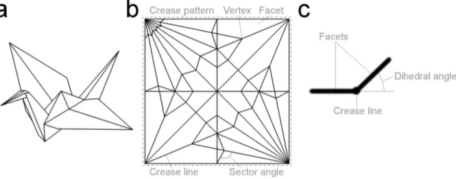
Origami in its original art form connotes the folding of a quadratic, flat piece of paper without cutting or gluing. An origami (Fig. 1a) is usually represented as a crease pattern (Fig. 1b) that depicts the location and distribution of the crease lines in the unfolded state. A vertex is a point at which a minimum of two crease lines intersect, and the angle between two intersecting crease lines is called a sector angle. The polygons between the crease lines are called facets, and the rotational angle between two facets is called a dihedral angle (Fig. 1c) that is zero radians in the unfolded, and ±π radians in the fully folded state.
Fig. 1: (a) Origami crane, (b) crease pattern of the origami crane with vertices, crease lines, facets, and sector angles, and (c) the dihedral angle of a crease line between two facets
2 In addition to popularizing the term origami, which has become the umbrella term for any type of folding independent of shape, material, or scientific field, Yoshizawa’s work led to a renaissance of folding when mathematicians, engineers, and artists recognized the benefits of origami. These benefits are numerous: origami is scale-independent [10] since the kinematics of folding depend on the sector angle relations that are preserved when scaled. The kinematics further allow for a compact or flat stowage in the unfolded state and complex three-dimensional motion during deployment [11]. The deployment can be achieved by a low number of Degrees-Of-Freedom (DOF), which minimizes the amount of resources required to actuate the folding motion and enables a reliable control [12]. The facilitated actuation and the complex motion then enable programmable structures that can change mechanical properties, shape, and function on demand [13, 14]. In addition, origami can be produced in the flat state and by additive manufacturing techniques [15], which enhances realization possibilities and simultaneously reduces the manufacturing cost and the assembly time.
Due to its benefits, the principle of origami offers potential for various scientific fields that pose different engineering design tasks. The transformation of origami into engineering applications includes an entire spectrum of more abstract to more direct implementations. The abstract end of the spectrum corresponds to so-called origami-inspired products [16] that fold and exhibit origami-like geometry but otherwise show little resemblance to origami. More closely related to traditional origami are origami- adapted mechanisms [17] that are based on origami crease patterns but use non-paperlike materials and accommodate for finite thickness. Finally, origami-applied systems [16] use paperlike material and exhibit little to no alteration of the underlying crease pattern. Together, these categories constitute the entire spectrum of origami-based design [18], which finds applications in mathematics [19], material science [20, 21], DNA [22] and biomedical research [23], mechanical engineering [24], robotics [14, 25- 28], consumer goods [29], architecture [30], and space [18, 31-33].
In recent decades, the widespread applicability of origami-based design has caused a wealth of research: while the year 2000 recorded about five hundred new scientific papers containing the word
“origami”, the number of publications per year has since increased by more than tenfold, resulting in a current total of almost one hundred thousand scientific works related to origami [34]. This substantial increase was accompanied by the adaptation and introduction of various computational methods and tools to facilitate the application of origami in engineering design tasks. A number of methods simulate the folding motion through various approaches including bar-and-hinge models [35-37], finite element
3 methods [38, 39], and simulators that assess the closure constraint of the surface [40]. Other computational algorithms target the generation of crease patterns [41-46] or adjust the geometry of existing ones [47, 48], plan the folding motion [49], analyze the mobility [50-52], and approximate surfaces [46, 53].
Despite the trend toward computer-aided design processes, today most crease patterns employed in technical applications are still designed manually or selected from a handful of well-known origami principles [11]. The most prominent of these principles is the Miura-ori pattern [54] that finds application in the packaging of large membrane structures [55], the design of tubes [56] and cylinders [57], surface approximation [53], and metamaterials [10, 20, 21, 58]. Other famous patterns include the Yoshimura [59] and Resch [48] tessellations, the Huffman grid [60], and many more [61]. Since all of these crease patterns have the potential to serve numerous engineering purposes, a large part of origami research focuses on the adaptation of these existing principles instead of searching for novel crease patterns. Computational algorithms that are capable of generating novel crease patterns are either targeted at artistic origami [44], limited to quadrilateral creased paper [45], result in patterns that are not rigidly foldable [46], or utilize ground structures that only allow for regular sector angle configurations and thus offer limited design freedom [41-43].
The lack of computational methods for the generative design of novel crease patterns targeted at engineering applications arises from a multitude of geometric complexities intrinsic to origami. First, many engineering applications require an origami to fold rigidly for the incorporation of rigid materials or electronics. Rigid foldability is the property of an origami that folds continuously from an unfolded to a folded state without deformation in its facets, which results in complicated geometric conditions for the sector and dihedral angles. Although extensively researched, there exist no such generic conditions for rigid foldability even for the simplest origami crease patterns. Second, each internal vertex in a crease pattern exhibits two Rigid Body Modes (RBMs) that allow for both “upward” and “downward” motion [62, 63], which results in an exponential number of possible motions with respect to the number of vertices involved. The RBMs are closely related to the assignment of mountain and valley crease lines determining the signs of all dihedral angles within a crease pattern, which has been proven to be NP- hard [64]. Third, because of the flat initial state and the multiplicity of closed kinematic chains, origami crease patterns represent complex multibody systems whose mobility cannot be assessed accurately by most conventional methods [65]. The mobility of an origami is influenced by both the topology and
4 the geometry of a crease pattern, which denote the number and distribution of crease lines between vertices and the location of these vertices, respectively. In particular, the topology and the geometry define the relations between the kinematic determinacy, the number of DOF, and the symmetry of a crease pattern, but the exact nature of these relations is still largely unexplored. Fourth, real-world applications do not allow for self-intersection, for which there still exist no intrinsic conditions. Finally, converting infinitely thin crease patterns into realizations with finitely thick materials imposes problems on both crease pattern and hinge design [66].
These complexities explain the challenges involved in the generation of novel crease patterns:
while many computational support tools isolate and tackle specific geometric problems, the synthesis of novel crease patterns encompasses all of the above complexities and thus represents the pinnacle of origami design. This pinnacle has not been reached by any related work, and today the design of novel origami crease patterns for engineering applications is tedious, time-consuming, and limited to a handful of experienced scientists [11]. This gap stipulates the need for a computational method capable of generating origami crease patterns to capitalize on the numerous benefits, the vast design space [67], and the widespread applicability of scientific origami.
1.1 Scope of the Thesis
Objective: The objective of this thesis is to develop a computational method for the synthesis of rigidly foldable crease patterns to support the application of origami in engineering design tasks.
The broad formulation of the objective requires two definitions to delineate the scope of this work, the first of which corresponds to the exact nature of the crease patterns analyzed and generated.
This thesis targets the synthesis of origami crease patterns that lie between origami-applied and origami- adapted structures [11]. The focus lies on unaltered crease patterns with zero thickness, pertaining to origami-applied mechanisms. Conversely, all crease patterns are required to fold rigidly, corresponding to non-paperlike materials and thus to origami-adapted structures. The rigidly foldable crease patterns are not restricted to conform to a quadratic shape in the unfolded state and neither cutting nor gluing is considered. If possible, the crease patterns in focus are developable, meaning that they can be folded from a flat surface [47]. In addition, the focus lies on crease patterns that exhibit a low number of DOF to facilitate a realization with the least possible amount of resources. A low number of actuators further enables a reliable control [12] that is beneficial especially for remote or hardly accessible environments for which origami engineering applications are often designed [42].
5 The second definition explains the nature of the engineering design tasks considered in this thesis. Since origami offers the realization of technical solutions for various scientific fields, the range of engineering design tasks to which the origami principle can be applied is broad, and can involve, e.g., forces [68], electromagnetic properties [69], or material characteristics [70]. Independent of their purpose, however, all design tasks realized by origami require crease patterns that exhibit an appropriate kinematic behavior. Hence, this thesis focuses on purely kinematic aspects of the engineering design tasks to explore the geometric capabilities of origami as a basis for the synthesis of new technical solutions.
To achieve the objective, this work addresses the following four research questions (RQs) that are closely related to the geometric challenges of origami:
RQ1: What are the characteristics of the search space of rigid foldability and what are the conditions for an origami to fold rigidly?
RQ2: How can the exponential number of RBMs be modeled kinematically?
RQ3: What are the relations between the kinematic determinacy, the number of DOF, and the symmetry of an origami crease pattern?
RQ4: How can the answers to RQ1-RQ3 be embedded within an automated, generative method to synthesize origami crease patterns?
1.2 Approach
To answer the RQs and achieve the objective, the approach taken in this work to developing a computational method targets the integration of six parts that constitute a Computational Design Synthesis (CDS) method, which is defined as the “algorithmic creation of designs; the organized, methodological modeling, implementation and execution of design creation on a computer” [71]. These six parts involve an input, the representation, evaluation, and generation of designs, the guidance through the design space, as well as an output, all of which are detailed in the following paragraphs.
Input: The input involves the definition of engineering design tasks that focus on the kinematic capabilities of origami. Such design tasks are usually expressed by a folded state for stowage and a deployed state for a specific purpose, or vice versa, and by the transition between these two states, i.e.
the actuation of the folding motion. The input considered in this work should thus incorporate an initial
6 crease pattern together with its actuation, a target shape or function, as well as possible spatial constraints, so that crease patterns can be tailored to their environment and the available resources.
Throughout this thesis, the exact definition of the input changes according to the current approach and will be explained in more detail in Sections 3, 4, and 5.
Representation: In general, the representation of designs within a CDS method defines the focus of the computational search and determines the exact approach taken by the method [71]. As such, the representation defines the means through which the designs are generated and evaluated, which is why choosing a suitable representation is a core task in the development of a CDS method. The representation of an origami should include both the topology and the geometry of the underlying crease pattern, for which there exist various ways in literature such as connectivity matrices [50, 51], diagrams [72], as well as undirected [73] and directed graphs [74]. The representation also involves the choice of suitable coordinates that define the mathematical framework. Related works include natural and relative coordinates [75] modeled by vertex locations as well as sector and dihedral angles, respectively, both of which are utilized in this thesis depending on the specific purpose.
Generation: Automatically generating design alternatives through computational methods is instrumental for the creation of novel designs. In complex design tasks with large search spaces, human designers may suffer from confirmation bias [76] and design fixation [77], the latter of which is expressed in origami research by the focus on existing crease patterns as explained above. The generation of origami crease patterns is mainly engaged with the challenges involved in the creation of crease pattern topologies, and related existing methods are presented in Section 2.6.
Evaluation: The evaluation of generated design alternatives usually represents the most time-intensive step in the conceptual design for engineering tasks [71]. Computationally automating the evaluation has the potential to speed up the design process and reduce the problems associated with the human- oriented selection process in growing search spaces [78]. Since origami exhibits vast search spaces [67] and complex three-dimensional motion, an efficient computational evaluation of the folding process is paramount. Due to the nature of the considered design tasks, in this thesis the evaluation of crease patterns focuses on the assessment of the kinematic behavior that involves rigid foldability, spatial configurations of folded and unfolded states, as well as intersection. A description of the related background is given in Sections 2.4 and 2.5.
7 Guidance: To replace the human selection process [79] and fully capitalize on the advantages offered by the computational generation and evaluation of design alternatives, a CDS method requires a suitable strategy to guide the exploration of the search space. In general, the guidance strategy makes decisions based on the outcome of previous evaluations and determines the following steps taken to adjust designs or generate new ones. Due to the few implementations of computational methods for the synthesis of crease patterns, guidance strategies in origami are understudied and often replaced by direct computational algorithms that implicitly incorporate the design of crease patterns, such as in [44].
The guidance strategies employed in this thesis are detailed in Sections 3 and 5.
Output: As soon as the termination criteria are met, a CDS method outputs the feasible design alternatives that in this thesis equate to rigid origami concept(s) that satisfy the prescribed engineering tasks. The term “concept” is used here to clarify that this work addresses all of the above-mentioned geometric complexities, i.e. rigid foldability, RBMs, mobility, and intersection, except the problem of finite thickness [66]. Although certain measures can be taken to conform crease patterns to the challenges of finite thickness, the origami concepts developed in this work still require adaptation to finite thickness after the application of the proposed methods.
1.3 Expected Contributions
The expected contributions are tied to the answers of the RQs and the achievement of the objective of this thesis:
RQ1: Since this work focuses on purely kinematic design tasks, large parts of the thesis are targeted at uncovering the mathematical underpinnings of rigid foldability. Although many related works are directed toward rigid foldability, a generic intrinsic condition for rigid foldability is missing even for the simplest origami crease patterns. Discovering such a condition and exploring the characteristics of the corresponding search space is expected to influence origami research on a fundamental level.
RQ2: The exponential number of RBMs exhibited by crease patterns plays an important role in the complexity of origami and the size of the vast design space. As further detailed in Section 2, kinematically modeling different RBMs through existing approaches is a cumbersome process, which is why the development of a reliable kinematic model to both discover RBMs and assess the corresponding kinematic behavior is a significant contribution to origami research.
RQ3: The relations between kinematic determinacy, the number of DOF, and the symmetry of crease patterns determine the mobility of origami mechanisms. Understanding these relations is expected to
8 contribute by offering an approach to generating kinematically determinate, rigidly foldable crease patterns whose folding motion is driven by the prescribed number of DOF.
RQ4: Addressing RQ1-RQ3 should provide solutions to the geometric challenges of origami. However, the discoveries made still have to be embedded within an automated method whose integration then contributes by combining the knowledge of origami design into one concise resource and by enabling the objective of this work.
Objective: In comparison to today’s manual-oriented design of origami crease patterns performed by specialists, automating the synthesis of origami crease patterns offers an improved approach to incorporating origami principles as a base for the development of novel technical solutions. Such a computational method contributes by generating and evaluating many more crease patterns than possibly assessed by human designers, by reducing the time-consumption and the tedium of human designers, and by creating novel origami crease patterns that expand the range of engineering design tasks realized by the application of origami.
1.4 Structure of the Thesis
The thesis is structured according to Fig. 2. Section 2 elaborates the important related works and presents the state-of-the-art in origami research, which highlights the gaps and the implications for this work. Section 3 presents a numerical approach to the computational method that specifically targets and partially answers RQ1 and RQ2 by introducing a kinematic simulation method that enables both the analysis of the search space of rigid foldability and the assessment of RBMs. The findings and shortcomings of the numerical approach then direct the work performed in Section 4, which completes the answers to RQ1 and RQ2 and provides an answer to RQ3 by investigating the analytical kinematics of origami. This investigation reveals deep insight into the mathematics of folding and builds a strong basis for an analytical approach to the computational method. This analytical approach is presented in Section 5 that combines the knowledge gathered by embedding the answers to RQ1-RQ3 within an automated computational synthesis (RQ4) to achieve the objective of this thesis. Section 6 discusses the findings and contributions with respect to the objective and the RQs and outlines the limitations and respective future paths. Finally, Section 7 summarizes the thesis and lists the major contributions of this work.
9 Fig. 2: Structure of the thesis
10
11 2 Background
This section covers the related background in rigid and flat foldability, mountain-valley assignments and RBMs, the simulation of the folding process, as well as the analysis and the generation of crease patterns. The section concludes by reiterating the research gaps that lead to the objective and the research questions of this thesis.
2.1 Rigid and Flat Foldability
Rigid foldability is the notion of a continuous folding process throughout which the facets of an origami stay undeformed, which requires all sector angles to remain constant. The entire folding motion then arises solely from rotations around the crease lines whose folded state is described by the dihedral angles. When an origami is rigidly foldable, its complex folding motion can be realized using exclusively stiff materials whose implementation is advantageous for, e.g., the embedding of electronics [80, 81] or the protection against the environment [33, 82, 83]. Although an onset of compliant origami mechanisms [84] has been taking place in recent years, rigid foldability still represents an important prerequisite for many technical applications, explaining the wealth of research directed toward rigid foldability and making it one of the most discussed topics in origami science.
Part of the research on rigid foldability focuses on the analysis of single vertices. The kinematics of a single vertex depend on the degree of the vertex, which denotes the number of incident crease lines. Miura proved that degree-1, degree-2, and degree-3 vertices cannot fold rigidly without collinear crease lines [85], and collinear crease lines are infeasible in rigid origami since all sector angles 𝛼 are constrained to be non-zero and strictly smaller than π, 𝛼 ∈ (0, π). Degree-4 vertices are the simplest rigidly foldable vertices and exhibit a single DOF [21, 74], meaning that the input of one dihedral angle determines the remaining dihedral angles and thus the complete folded state of the vertex [86]. Huffman [60] was one of the first to research single vertices of degree four to derive relations between sector and dihedral angles using the concept of Gaussian curvature. The same concept was used by Lang et al.
[87] to prove compatibility conditions between opposite pairs of dihedral angles. In addition, the kinematic behavior of all possible sector angle configurations of degree-four vertices are catalogued by Waitukaitis and van Hecke [88]. Since each additional crease line added to a vertex brings an additional DOF that increases the level of geometric complexity, much less is known about the rigid foldability of higher order vertices. Although there exists an approach to determining symbolic equations for the unknown dihedral angles [89], known conditions for rigid foldability usually apply only to specific types
12 of crease patterns [59, 90-94], and there is no generic approach capable of determining analytical conditions for the rigid foldability of degree-𝑛 vertices. The limits of the rigid motion of generic degree-𝑛 vertices with 𝑛 ≥ 4 can only be assessed using a diagram method [72] or approaches that numerically assess the closure constraint of a vertex, which is satisfied if the multiplication of all rotation matrices on a closed path around a vertex results in the identity matrix [74].
The closure constraint approach also enables the assessment of multi-vertex crease patterns when all the closed paths around the vertices within a crease pattern are examined [95]. Other approaches to judging the rigid foldability of multi-vertex crease patterns are the afore-mentioned diagram method [72], adapted mobility rules for patterns exhibiting symmetry [50, 51], and the fold angle multipliers [91] that are based on findings for flat foldability.
Flat foldability determines whether a rigid origami can fold from the initial flat state into a final folded state that is also completely flat [96]. This second flat state enables efficient packaging desired in many engineering applications [54], which renders flat foldability the second most discussed mathematical notion in origami after rigid foldability.
The most prominent condition for flat foldability is the Kawasaki-Justin condition [97, 98] that states that the sum of all even sector angles is equal to the sum of all odd sector angles:
𝛼 − 𝛼 + 𝛼 − 𝛼 + ⋯ − 𝛼 = 0 (1)
This condition is derived from the two-colorability of a single vertex and is thus only valid for vertices of even degree, whereas an equivalent condition for vertices of odd degree does not exist.
A special set of conditions applies to flat foldable degree-4 vertices, for which Tachi [30, 99]
identified that the ratio of half-angle tangents between all fold pairs in a developable and flat foldable quadrilateral mesh is constant, independent of the folded state. Based on these findings, Evans et al.
[91] presented the above-mentioned fold angle multipliers to analyze rigidly foldable origami twists.
Since the fold angle multipliers are based on relations for rigid foldability, they can be used as conditions for the rigid foldability of quadrilateral creased paper [99]. In addition, they are the only evidence that the conditions for rigid and flat foldability could be related.
2.2 Mountain-Valley Assignment and Rigid Body Modes
The initial flat state of an origami crease pattern is a singular state [100, 101] that allows for many different branches of motion arising from both positive and negative values of dihedral angles. A
13 mountain-valley (MV) assignment of a crease pattern determines for each crease line if it folds down (mountain) or up (valley). Bern and Hayes proved that such an MV assignment for an arbitrary crease pattern is NP-hard [64]. With respect to flat foldable and even-degree vertices, Maekawa’s condition states that the number of mountain creases 𝑛 and the number of valley creases 𝑛 differ by two, 𝑛 − 𝑛 = 2, or vice versa. The extension of Maekawa’s condition to degree-𝑛 vertices stems from Abel et al.
[62] who proved that any rigidly foldable vertex requires either a bird’s foot or a cross, both of which are specific MV assignments that prescribe the parity of certain subsets of crease lines.
Closely related to the MV assignment are the RBMs of a vertex that determine if a vertex on the interior of a crease pattern [62] folds up or downward. Fig. 3 [102] shows the example of a crease pattern that corresponds to one side of a six-sided flasher pattern [17]. The crease pattern consists of 𝑁 = 2 internal vertices and thus results in 2 [63], or 4 RBMs shown from left to right.
Fig. 3: Four RBMs from left to right of one side of a six-sided flasher pattern folding from top to bottom All four RBMs exhibit different motions and final folded states, all of which might satisfy or dissatisfy spatial requirements or constraints pertaining to a given engineering design task. To determine the fitness of a crease pattern with respect to a design task, this considerable difference in kinematic behavior exhibited by all crease patterns requires special attention within a computational method that must incorporate the assessment of different RBMs.
14 2.3 Simulation of the Folding Process
Approaches to simulating the origami folding process involve bar-and-hinge models, Finite Element (FE) analyses, and the Rigid Origami Simulator by Tachi [40]. The latter tries to satisfy the closure constraint of the surface on all paths around vertices by solving the pseudo-inverse of the Jacobian matrix to determine the unknown dihedral angles at each time step. This approach requires a valid MV assignment and thus some prior knowledge about the underlying crease pattern. However, the generation of novel crease patterns does not provide any information about valid MV assignments, rendering the Rigid Origami Simulator inapplicable to the automated evaluation of generated crease patterns.
FE analyses [38, 39] discretize the surface of the origami and make use of mathematics derived from plate structures. These works focus more on the practical implementation of origami rather than the strictly kinematic behavior since they model the elastic behavior of materials and allow for bending and stretching.
Filipov et al. [35] present a combination of FE analyses and bar-and-hinge models. Instead of discretizing the surface into small elements, this approach models quadrilateral facets by introducing fewer nodes per facet and by only then applying FE principles, which enables a more efficient structural analysis of origami mechanisms compared to conventional FE methods. However, generalizing the approach for facets with more than four sides might involve considerable future work since the results are dependent on the exact amount and placement of the introduced nodes.
Purely kinematic bar-and-hinge models are presented by Cai [37] et al. and Diaz [36]. In both works, the sides and diagonals of all facets are replaced by bars that correspond to a length constraint between two vertices 𝑣 and 𝑣 in the form
𝑥 − 𝑥 + 𝑦 − 𝑦 + 𝑧 − 𝑧 − 𝑙 = 0 (2)
where 𝑥, 𝑦, and 𝑧 are the coordinates in the Euclidean coordinate system and 𝑙 is the initial distance between the two vertices. Diaz [36] then minimizes the difference in length of all bars to determine the vertex locations, while Cai et al. [37] solve the Jacobian matrix of the constraint system at each time step of the folding process. In relation to an automated approach for origami design, these bar-and- hinge models are promising since they offer a simple, scalable, and time-efficient way to simulate the kinematic behavior of an origami crease pattern, but their implementation in related works lack the search for different RBMs.
15 Preliminary work [102] by the author introduced a bar-and-hinge simulator that detects RBMs by perturbing all vertices slightly in different directions. However, the Jacobian of the constraint system is solved by using the Newton-Raphson scheme [75], which is prone to divergence if the underlying crease pattern is not rigidly foldable. Since arbitrarily generated crease patterns are not generally rigidly foldable, the approach provides only a binary result for rigid foldability without any feedback to determine the adjustment of the geometry required for rigid foldability.
2.4 Analysis of Crease Patterns
The analysis of a crease pattern is mainly concerned with the assessment of the crease pattern topology to determine if the underlying graph is kinematically determinate. Kinematic determinacy expresses the notion that the number of existing mechanisms within a structure is equal to the respective number of DOF [103], which is the prerequisite for a well-defined motion.
The kinematic determinacy of an origami can in general be analyzed by calculating the rank of the Jacobian matrix and by comparing the result to the number of unknowns [37]. If these numbers match, a crease pattern can fold rigidly with the respective actuation. If the matrix rank is smaller than the number of unknowns, the system is underconstrained and requires a more rigorous control to fold in a determinate way. In contrast, overconstrained structures play a significant role in origami [99], a phenomenon well studied for quadrilateral creased paper [93] by the introduction of the fold angle multipliers [91]. For crease patterns including higher order vertices, overconstrained but rigidly foldable mechanisms are not reported in origami literature but could in general be analyzed by adapted mobility rules [50, 51] or other related methods [65].
2.5 Generation of Crease Patterns
A long-standing tradition in the generation of origami crease patterns is the adaptation of fold patterns that appear in nature. Examples are the Miura-ori pattern that copies corrugated metal tubes and flower leaf surfaces [104], patterns found on insect wings [3], pinecones, and many more [105].
Lang’s Treemaker [44] represents the sate-of-the-art for the generation of artistic crease patterns. This computational algorithm optimizes the distribution of circles within the quadratic piece of paper and creates the required number of flaps that can then be folded into intricate origami models by experienced origami design practitioners. Another generative algorithm for artistic origami is the Origamizer [46] that approximates polyhedral surfaces by creating detailed crease patterns involving advanced crimp folds. However, neither of these approaches guarantees rigid foldability.
16 An approach that does guarantee rigid foldability is based on the fold angle multipliers that can also be introduced as design features instead of checks for rigid foldability. This reversed usage of fold angle multipliers enables the generation of quadrilateral creased paper [45] by designing all vertices so that they satisfy a set of conditions for flat foldability. The fully determinate algorithm then generates quadrilateral, flat foldable, and overconstrained crease patterns that fold rigidly. The approach, however, is limited to fold angle multipliers and thus to degree-4 vertices, and no related condition has been reported for higher order vertices.
The last class of generative approaches [41-43] relates to structural topology optimization and is based on a discretized ground structure. By representing this ground structure as a genotype, each element can be switched on or off and the resulting patterns are optimized using Genetic Algorithms.
This procedure requires vast amounts of objective function evaluations, which demands a coarse ground structure in which all sector angles are radians or multiples thereof. Such regular sector angle configurations restrict the design freedom and lead to crease patterns with limited functionality.
2.6 Discussion
Rigid foldability is well researched with respect to degree-4 vertices, but angle relations for higher order vertices are understudied or completely missing. No method is currently able to determine the analytical conditions for the rigid foldability of degree-𝑛 vertices, and the limits of the rigid motion of these vertices can only be assessed using numerical approaches. In addition, analytical conditions for flat foldability only exist for even-degree vertices. These findings drive RQ1.
The available numerical simulators are resourceful, but they either require valid MV assignments, include forces and material properties, or do not focus on the discovery of RBMs. Since each crease pattern exhibits an exponential number of RBMs, being able to kinematically model different RBMs is paramount for an efficient search through the vast design space of origami, as targeted by RQ2.
Methods for assessing the mobility of origami crease patterns exist, but they either require elaborate Jacobian matrix rank calculations or focus on the analysis of the kinematic behavior rather than the generation of crease patterns. To enable a reliable method for the generative design of origami crease patterns, the mobility of origami mechanisms must be better understood, as expressed by RQ3.
17 The existing generative methods either focus on the manual adaptation of natural crease patterns, generate artistic origami without guaranteeing rigid foldability, are limited to quadrilateral creased paper, or rely on ground structures that limit the design freedom. These methods do not sufficiently leverage the benefits offered by origami for the realization of novel technical solutions, which is why the objective of this work is the development of a new generative method for the synthesis of crease patterns to support the application of origami in engineering design tasks.
18
19 3 Numerical Approach to the Computational Method
The content of Section 3 has been published as: [106] Zimmermann, L., Shea, K., and Stanković, T.,
“Origami Sensitivity – On the Influence of Vertex Geometry,” in Proceedings of Origami7: Seventh International Meeting of Origami Science, Mathematics and Education, 2018, p. 1087-1102.
This section presents the first approach (Fig. 4) to achieving the objective of the thesis. As described in the last section, establishing such an approach first requires more knowledge about rigid foldability (RQ1) as well as the evaluation of the folding motion and the RBMs (RQ2). The approach presented here simultaneously addresses RQ1 and RQ2 by introducing a new kinematic simulation method that enables the examination of the search space of rigid foldability and the assessment of RBMs. At this point, advanced analytical conditions for rigid foldability are missing, which is why the new kinematic simulation and thus the overall approach are realized through purely numerical means. Due to the absence of generative methods that satisfy the given requirements, the automated generation step of the planned CDS method is substituted in this section by the manual adaptation (Fig. 4) of an existing crease pattern, similar to the generation approach in related works.
Fig. 4: Workflow of the numerical approach to the computational method
The section first presents the representation of crease patterns and introduces the kinematic simulation. Then, a flasher pattern is manually adapted to fold rigidly and, based on this pattern, an engineering design task is presented. Subsequently, a sensitivity analysis is performed to investigate
20 the search space of rigid foldability (RQ1) and to assess the kinematic behavior with respect to the RBMs (RQ2). Following the sensitivity analysis, a suitable method is selected to guide the optimization of the flasher pattern within an automated loop as shown in Fig. 4. Finally, the section presents the resulting origami concept and discusses the findings.
3.1 Representation
Crease patterns are implicitly represented as undirected graphs 𝐺 = (𝑉, 𝐸) where 𝑉 is a non- empty set of vertices 𝑣 and 𝐸 is a non-empty set of edges 𝑒. Explicitly, crease patterns are represented as a bar-and-hinge model since such models are scalable, simple to implement, and lead to sparse constraint matrices that can be solved by fast algorithms. The constraints are formulated according to Eq. (2) using vertex coordinates 𝐱 represented by both natural and relative coordinates [75] in both Cartesian and spherical coordinates depending on the task at hand. The geometric distribution and locations of all vertices within a crease pattern will be collectively called the vertex geometry.
3.2 Evaluation
Since arbitrary generated vertex geometries do not generally lead to rigid foldability, the simulation method needs to be able to evaluate both rigidly and non-rigidly foldable crease patterns in order to be applicable within a computational synthesis of crease patterns.
By representing an origami through the locations of vertices, rigid foldability equates to constant Euclidean distances between all vertices that belong to the same facet. In contrast, facets in non-rigidly foldable patterns experience bending and stretching, and the Euclidean distances between vertices of the same facet change. In bar-and-hinge models, the folding motion of a crease pattern is usually driven by a set of parametric vertex trajectories. Fig. 5 depicts the schematic example of a single bar between two vertices 𝑣 and 𝑣 that is “folded” from an initial vertical into a horizontal position by three different trajectories from left to right in 𝐽 = 2 total iterations. The trajectory in the middle (black, dashed) of Fig.
5 is a perfect quarter circle, which is why the initial Euclidean distance, called the target length 𝑙, between the initial vertex locations 𝐱( ) and 𝐱( ) is equal to the actual length 𝑙( ) in all iterations 𝑗. If all Euclidean distances in a crease pattern behave in the same way, the crease pattern is rigidly foldable.
However, the trajectories on the left and right-hand side of Fig. 5 shorten and elongate the bar, respectively, and the actual lengths 𝑙( ) and 𝑙( ) are not equal to the target length 𝑙. This length change leads to a motion that is not rigidly foldable, as characterized by the errors 𝜀( ) and 𝜀( ).
21 Fig. 5: The same vertical bar is “folded” from an initial vertical into a horizontal position by three different trajectories. While the bar folds rigidly for the case in the middle, it shortens and elongates on the left and the right side, respectively.
The basic idea of the simulation method is to allow these errors but to minimize the difference between the actual and the target Euclidean distance between vertices to obtain a measure for the total distortion of the crease pattern. Instead of imposing explicit conditions for rigid foldability, the distortion is presented as an error that can then be guided towards zero by optimizing the vertex geometry.
3.2.1 Input to the Simulation
The input to the simulation is a crease pattern with vertices and edges, the initial locations of the vertices, boundary conditions such as fixed vertices or facets, and one or multiple vertex trajectories that drive the motion of the origami in a desired number of iterations 𝐽.
3.2.2 Constraints and Solving Procedure
First, the simulation method obtains all target lengths 𝐥 from the initial crease pattern provided by the input. The number of target lengths 𝑞 corresponds to the Euclidean distances of the sides and diagonals of all facets in the crease pattern according to Diaz [36]. Because the actual lengths 𝐥( ) may shorten or elongate in each iteration 𝑗, the constraint system is composed of the absolute of the difference between 𝐥( ) and 𝐥, which is kept lower or equal to small and strictly positive values in the error vector 𝛆( ). This is formulated as two sets of constraints bounded by – 𝛆( ) and 𝛆( ) from below and above, respectively. The errors are then summed over all 𝑞 constraints and presented as the distortion 𝛿( ) that is minimized in each iteration 𝑗 with respect to the errors 𝛆 and the vertex locations 𝐱. This procedure is stated as a constrained nonlinear optimization problem in Eq. (3) that is solved using the function FindMinimum in Mathematica 10 with default settings. FindMinimum uses the Interior Point
22 method [107] that requires a starting point for the optimization, here defined as the vertex locations in the previous iteration 𝑗 − 1 for the search of vertex locations in the current iteration 𝑗.
min𝛆,𝐱 𝛿( )= 𝜀( )| − 𝜀( )≤ 𝐥( )− 𝐥( )≤ 𝜀( ) (3) 3.2.3 Rigidity Error
If the distortion satisfies 𝛿( )≤ 10 in each iteration 𝑗 (Section 3.5.2 will show how this boundary is defined), all folding steps exhibit numerical rigid foldability and the crease pattern is globally rigidly foldable for the given actuation with a reasonably high number of iterations 𝐽. To obtain a single measure for each simulation, a rigidity error 𝛤 is defined as the averaged sum of the distortions 𝛿( ) over all iterations 𝐽:
𝛤 =1
𝐽 𝛿( ) (4)
3.2.4 Self-Intersection
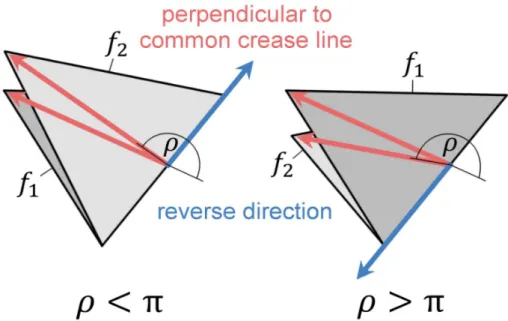
All facets are decomposed into triangles and subjected to a triangle-triangle intersection check by Möller [108] in each iteration 𝑗. This check, however, does not necessarily detect dihedral angles that exceed the allowed range of ±π and may thus neglect the intersection of two adjacent facets. Hence, the intersection check is extended by calculating two vectors for all pairs of adjacent facets, each vector lying in the respective facet plane and pointing away perpendicularly from the common crease line. Fig.
6 shows these vectors in red for two adjacent facets 𝑓 and 𝑓 angled at a dihedral angle 𝜌 that is smaller than π on the left and greater than π on the right.
Fig. 6: Two adjacent facets angled at dihedral angles 𝜌 that are smaller (left) and greater (right) than π.
The vectors perpendicular to the common crease line are shown in red, and the cross product vector that reverses its direction is shown in blue.
23 Once 𝜌 approaches the boundary of its allowed range, the cross product of the vectors perpendicular to the common crease line is compared for successive iterations, and an intersection is detected if the resulting vector reverses its direction, as illustrated in Fig. 6 by the blue vectors.
The measure for self-intersection 𝛩 provided by the simulation method is defined as the number of iterations in which self-intersection occurs, averaged over all iterations 𝐽.
3.2.5 Output of the Simulation
The output for each simulation of a folding motion is the rigidity error 𝛤 and all distortions 𝛿( ), the measure for self-intersection 𝛩, as well as the locations of all vertices in the last iteration 𝑗 = 𝐽 to assess the shape of the folded origami.
3.3 Generation: Manual Adaptation of a Flasher Pattern
To address RQ1 and RQ2, the simulation method needs to be applied to a crease pattern that offers a suitable topology for the investigation of the kinematic search space. An origami flasher (Fig. 7 left) is a pattern first introduced by Palmer and Shafer [109] and represents the principle of wrapping a piece of paper around its vertical axis. In technical applications, flashers are employed, e.g., for solar panels [17] since the pattern can be folded into an enclosed space of a launch vehicle and, once deployed, exhibits a large surface area that enables the collection of solar energy. Flashers exhibit a low number of DOF (one per side), which facilitates the actuation of the folding process through a low number of actuators.
Currently, existing flasher patterns do not fold rigidly because they are overconstrained, and the only way flashers have been shown to fold rigidly is by introducing cuts [87]. However, Zirbel et al. [17]
hint at the possibility of rigidly foldable flashers if more crease lines were introduced along the diagonals within some of the quadrilateral facets. Indeed, folding a paper model of a four-sided flasher reveals these crease lines around which the quadrilateral facets 𝑓 and 𝑓 bend (Fig. 7).
Fig. 7: Existing four-sided flasher pattern (left) and adapted flasher pattern (right) that folds rigidly because of the additional crease lines
24 Introducing these crease lines leads to a novel flasher pattern (Fig. 7 right), here called the adapted flasher, whose kinematic determinacy can be analyzed by subjecting it to various methods listed in Section 2.5. Here, the matrix rank method by Cai et al. [37] is applied, which yields a Jacobian matrix rank of fifteen for fifteen unknowns (five vertices in motion, each with three coordinates 𝑥, 𝑦, and 𝑧), confirming that the pattern is kinematically determinate. In addition, the rigid foldability is assessed by simulating the adapted flasher with the simulation method introduced in Section 3.2. To fold the adapted flasher, the central facet 𝑓 in Fig. 7 (left) is fixed in space and 𝑓 as well as its symmetric equivalents are folded around the shared crease lines by − radians. Fig. 8 depicts the folding motion of the adapted flasher from left to right, resulting in a rigidity error 𝛤 = 1.6 ∗ 10 and distortions 𝛿( )≤ 10 ∀𝑗, which numerically demonstrates that the adapted flasher is indeed rigidly foldable.
Fig. 8: Adapted flasher pattern folding rigidly from left to right
While the adapted flasher is rigidly foldable, a problem arises with respect to its folded shape:
flashers are supposed to fold completely into a vertical cuboid shape, similar to a downward extrusion of the central facet. As depicted in Fig. 8 on the right, however, the adapted flasher is still partly unfolded after the above-described actuation, and an additional actuation of the outer layers would have to be introduced to completely fold the pattern into a cuboid. This sequential folding demands more actuators and complicates the control of the adapted flasher, which renders the adapted flasher less attractive for practical applications and leads to the formulation of the design task.
3.4 Design Task
To mimic the behavior of non-rigidly foldable flashers in a solar panel scenario, the goal of the design task for the remainder of Section 3 is to optimize the vertex geometry of the adapted flasher such that it folds into the red cuboid illustrated in Fig. 9b while maintaining a maximally large surface area for the collection of solar energy. The crease pattern in focus is the truncated flasher pattern depicted in Fig. 9a, which shows the allocation of vertices for one side of the four-sided pattern. The input to the kinematic simulation is a total number of iterations 𝐽 = 30 and the crease pattern in Fig. 9a with vertices
25 and edges. The center of facet 𝑓 is fixed at the origin 𝑂 and no rotation is allowed. The vertex 𝑣 is located at 𝐱 ( )= (1, 1, 0), which defines the enclosing volume as a cuboid (Fig. 9b) of the dimensions
−1 ≤ 𝑥 ≤ 1, −1 ≤ 𝑦 ≤ 1, −4 ≤ 𝑧 < 0. Note that the strict inequality for the upper boundary of 𝑧 prevents self-intersection with the facet 𝑓. The locations of the remaining vertices 𝑣 are not determined yet and have to be adjusted to satisfy the design task.
Fig. 9: (a) Rigidly foldable four-sided flasher pattern whose folded state should eventually fit into the depicted cuboid (b)
3.5 Sensitivity
In this section, the adapted flasher pattern is subjected to a sensitivity analysis to examine the influence of the vertex geometry on the kinematic behavior of the pattern. The focus of the analysis lies on the visualization of the kinematic search space characteristics to precipitate a better understanding of the kinematic behavior, in particular of the rigid foldability (RQ1) and the RBMs (RQ2).
The pattern in Fig. 9a can be perceived as being composed of ring-wise layers. The 0 layer consists of the central facet 𝑓, the first layer is bounded by vertices 𝑣 , 𝑣 and their rotations, and the second layer is bounded by vertices 𝑣 , 𝑣 and their rotations (such as 𝑣 ). The sensitivity analysis of the adapted flasher is structured layer-wise from inside to outside. First, the sector angles of 𝑣 are examined in relation to rigid foldability in order to fix a starting location for 𝑣 that then remains constant throughout the sensitivity analysis. This step also determines the trajectory of 𝑣 and thus the actuation that is required as an input to the simulation. Subsequently, the effects of the starting location of 𝑣 on the kinematic behavior of the first layer are analyzed, after which the influence of the starting location of 𝑣 on the behavior of the entire crease pattern is demonstrated.
26 3.5.1 Sector Angles around 𝑣
Vertex 𝑣 of the adapted flasher is a degree-5 vertex and thus perfectly suited for an analysis of rigid foldability since there exists little data on the rigid foldability of degree-𝑛 vertices for 𝑛 > 4. To do so, the outermost layer of the adapted flasher is ignored for now and the kinematic properties of 𝑣 are visualized by the rigidity error 𝛤 over two sector angles.
To parametrize 𝑣 with two sector angles, three of its five sector angles need to be eliminated.
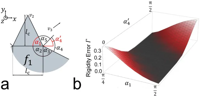
Vertex 𝑣 in Fig. 10a is developable, which eliminates 𝛼 = 2π − ∑ 𝛼. As defined by the starting location of 𝑣 , the facet 𝑓 is a square, and 𝛼 = . To conform the motion of the adapted flasher to the conventional flasher design [87], the 𝑦-axis component of the starting location of 𝑣 is constrained to 𝑦( )= 1 + 𝑙 = 3, where 𝑙 is the side length of the central facet 𝑓 (Fig. 10a). This constraint then leads to 𝛼 = , which leaves the two remaining parameters 𝛼 and 𝛼 . To decouple these parameters, instead of 𝛼 the sensitivity is performed with the sector angle 𝛼 (Fig. 10a) that starts from the stationary axis 𝑦 = 1.
Fig. 10: Parametrization of sector angles around 𝑣 (a) and the rigidity error 𝛤 for ≤ 𝛼 ≤ and 0 <
𝛼 < , revealing a “rigid foldability valley” (b).
Fig. 10b shows the result of the rigidity error 𝛤 for ≤ 𝛼 ≤ and 0 < 𝛼 < and reveals a smooth surface that exhibits the shape of a valley. The valley is constituted by both a flat bottom of constant width that runs linearly across the search space and by slopes that rise monotonically on either side. The sector angle configurations in the valley correspond to rigidly foldable vertex geometries satisfying 𝛿( )≤ 10 ∀𝑗, whereas the configurations on the slope of the valley are not rigidly foldable.