Nanowire-based thermoelectric ratchet in the hopping regime
Riccardo Bosisio,1,2Genevi`eve Fleury,3,*Jean-Louis Pichard,3and Cosimo Gorini4
1SPIN-CNR, Via Dodecaneso 33, 16146 Genova, Italy
2NEST, Instituto Nanoscienze-CNR and Scuola Normale Superiore, I-56127 Pisa, Italy
3SPEC, CEA, CNRS, Universit´e Paris-Saclay, CEA Saclay 91191 Gif-sur-Yvette Cedex, France
4Institut f¨ur Theoretische Physik, Universit¨at Regensburg, D-93040 Regensburg, Germany (Received 22 October 2015; published 4 April 2016)
We study a thermoelectric ratchet consisting of an array of disordered nanowires arranged in parallel on top of an insulating substrate and contacted asymmetrically to two electrodes. Transport is investigated in the Mott hopping regime, when localized electrons can propagate through the nanowires via thermally assisted hops. When the electronic temperature in the nanowires is different from the phononic one in the substrate, we show that a finite electrical current is generated even in the absence of driving forces between the electrodes. We discuss the device performance both as an energy harvester, when an excess heat from the substrate is converted into useful power, and as a refrigerator, when an external power is supplied to cool down the substrate.
DOI:10.1103/PhysRevB.93.165404
I. INTRODUCTION
The first golden age of thermoelectricity dates back to Ioffe’s suggestion in the 1950s of using semiconductors in thermoelectric modules [1]. In spite of sustained efforts, it only led to thermoelectric devices limited by their poor efficiency to niche applications. Interest in thermoelectricity was revived in the 1990s by nanostructuration and the appealing perspectives of enhanced efficiency it offers [2,3]. Nowadays the idea of exploiting multiterminal thermoelectric setups is driving the field through a new season of very intense activity [4–35].
In contrast with conventional two-terminal thermoelectrics, multiterminal thermoelectrics aims at studying a conductor connected, in addition to the two reservoirs at its ends, to (at least) one other reservoir, be it a mere probe [4–8,21], a normal electronic reservoir [9–11], a superconducting lead [11–14], or a reservoir of fermionic [15–17,21,22] or bosonic [23–34,36] nature that can only exchange energy with the system. Investigations carried out so far have shown that the multiterminal geometry has generally a positive impact on the performance of the thermoelectric devices [7,9,13,21,30], compared to their two-terminal counterparts. It also opens up new perspectives, such as the possibility of implementing a magnetic thermal switch [10] or of separating and controlling heat and charge flows independently [13].
In the following we focus on three-terminal thermoelec- tric harvesters, which can be also viewed as three-terminal thermoelectric ratchets using excess heat coming from the environment to generate a directed electrical current through the conductor. The dual cooling effect, enabling us to cool down the third terminal by investing work from voltage applied across the conductor, is also studied. One of the first proposed realizations of three-terminal thermoelectric harvester was a Coulomb-blockaded quantum dot [15] exchanging thermal energy with a thirdelectronicbath, capacitively coupled. Its feasibility has been recently confirmed experimentally [18,19], though the output power turns out to be too small for practical purposes. Since then, other quantum-dot- or quantum-well-
*genevieve.fleury@cea.fr
based devices have been put forward [16,17] with the hope of overcoming the problem. On the other hand, various devices running on energy exchanges with a thirdbosonicreservoir have been discussed. In particular, phonon-driven mechanisms have been considered at a theoretical level in two-levels systems or chains of localized states along nanowires (NWs) in the context of phonon-assisted hopping transport [31,32,37].
More generally, NW-based devices have been at the heart of experimental studies on future thermoelectrics for over a decade [38,39]. Two critical advantages of such setups are nanostructuration [3,40,41] and scalability [42–46], the latter being a crucial requirement for substantial output power.
Furthermore, NWs are core products of the semiconductor industry, commonly fabricated up to large scales and used in a broad range of applications, from thermoelectrics to photovoltaics [47,48] or biosensing [49].
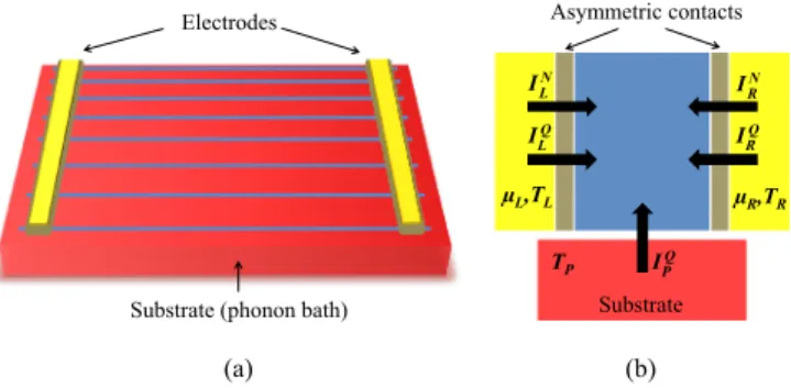
In light of the above, the energy harvester/cooler we pro- pose is a NW-based three-terminal thermoelectric ratchet, as sketched in Fig.1. A set of disordered (doped) semiconductor NWs is connected in parallel to two electronic reservoirs and deposited on a substrate. The electronic states in the NWs are localized by disorder, but transport is possible thanks to phonons from the substrate, which allow activated hops between the localized states [50,51]. In two recent works [33,34] we showed that similar setups exhibit remarkable local(two-terminal) thermoelectric properties. This is mainly because in the hopping regime the transport energy window around the Fermi level is much larger than the thermal energy, i.e., the one of conventional band transport, making it possible to exploit particle-hole asymmetry across a wide energy range.
Therefore the thermopower which is a direct measure of the
“degree” of particle/hole asymmetry can possibly reach large values, somehow compensating—regarding thermoelectric performance—the smallness of the electrical conductance in the hopping regime.
In the present paper, we explore the potential of our device in the phonon-assisted activated regime fornon-local thermoelectric conversion (the core idea behind multiterminal thermoelectrics). More precisely, we are mainly interested in harvesting waste heat from a hot substrate (the third terminal) to generate an electric current between the two
ILN ILQ
INR IRQ
IPQ Substrate (phonon bath)
Electrodes
Substrate TP
µL,TL µR,TR Asymmetric contacts
(a) (b)
FIG. 1. (a) Sketch of the NW-based ratchet studied in this paper.
A large array of parallel disordered NWs (in blue) is deposited onto an insulating substrate (in red) acting as a phonon bath. The NWs are attached to metallic electrodes (yellow) via asymmetric contacts. (b) Schematic of the three-terminal transport. Electrons inside the NWs are localized within their impurity band (blue) and can exchange phonons with the substrate (held at temperatureTP). Under condition of asymmetric couplings (gray strips) to the electrodes (yellow), this can generate net currents flowing through the NWs. The particle and heat currents between the NWs and the three reservoirs are represented by the arrows, assuming they are positive when they enter the system.
electronic reservoirs, thus supplying a load. The process requires to define ratchet pawls forcing charge carriers to escape the NWs preferably on one side. Quite generally, this can be achieved by breaking spatial mirror symmetry (see, e.g., Refs. [52–54]). Particle-hole symmetry need be broken as well, which is the basic requirement for any thermoelectric device. Both symmetry-breaking conditions are implemented by inserting different energy filters at the left and right metal-semiconductor contacts. Two simple models of energy filter mimicking a Schottky barrier and an open quantum dot are discussed in detail. The thermoelectric ratchet power factor Q, characterizing its output power in the heat engine configuration, and the electronic figure of meritZT, controlling its efficiency in the absence of parasitic phonon contribution, depend on the choice of contact type and the degree of asymmetry. Remarkably, both quantities reach max- imum values in the same range of parameters, i.e., large values ZT 1 at high (scalable) output powersQcan be obtained.
In all respects, the three-terminal nonlocal thermoelectric converter is found to be much more performant that the corresponding local, two-terminal one. Besides waste heat harvesting, we also briefly study the refrigerator configuration, in which a current flowing in the NWs can be used to cool down the phonon bath.
The outline is as follows. In Sec.II, we describe the model and the (numerical) method used to calculate the currents and the thermoelectric coefficients. In Sec.III, we discuss different implementations of ratchet pawls at the metal-semiconductor contacts and show the ratchet effect, i.e., the conversion of excess heat from the substrate into a directed electrical current. Sec.IVis dedicated to the estimation of the device performance. We conclude in Sec. V. Two appendices are added to discuss additional results.
II. MODEL AND METHOD
Phonon-activated transport through the NW-based ratchet [Fig.1(a)] is described in linear response, and thus character- ized by a three-terminal Onsager matrix. The latter is defined in Sec.II A. The way it is computed, by solving the random resistor network problem, is briefly reviewed in Sec.II B.
A. Onsager formalism for the three-terminal thermoelectric device
We consider a conducting region connected to two elec- tronic reservoirs L and R at equilibrium, characterized by electrochemical potentialsμL,μR, and temperaturesTL,TR, and to a bosonic reservoirP at temperatureTP[see Fig.1(b)].
Heat and particles can be exchanged withLandR, but only heat withP. The particle currentsILN,IRN, and the heat currents ILQ,IRQ,IPQare defined positive when entering the conducting region from the reservoirα=L,R,P. The right terminalRis chosen as reference (μR≡μandTR ≡T) and we set
δμ=μL−μR, δT =TL−TR,andδTP =TP−TR. (1) In linear response the independent currentsILN,ILQ, andIPQare expressed `a la Onsager in terms of the corresponding driving forces
⎛
⎜⎝ ILN ILQ IPQ
⎞
⎟⎠=
⎛
⎝L11 L12 L13 L12 L22 L23 L13 L23 L33
⎞
⎠
⎛
⎝ δμ/T δT /T2 δTP/T2
⎞
⎠. (2)
In writing the above we have exploited the Casimir-Onsager relations [55] Lij =Lj i for i=j, valid in the absence of time-reversal symmetry breaking.
In the following we focus on the specific caseδT =0, that is, the system and the electronic reservoirs share the same temperatureT. On the other hand, we considerδμ,δTP =0 and discuss several possibilities offered by this setup in terms of energy harvesting (when the heat provided by the phonon bath is exploited to produce electrical work) and cooling (when an external work is invested to cool down the phonon bath).
B. Nanowire array in the phonon-assisted activated regime The device [see Fig.1(a)] is realized by depositing a set ofMdisordered NWs in parallel onto an insulating substrate (which plays the role of a phonon bath) and connecting them asymmetrically to two metallic electrodes (acting as electron reservoirs). The electrodes are assumed to be thermally isolated from the substrate (not highlighted in Fig.1) such that the electron and phonon reservoirs can be held at different temperatures. Each NW is modeled as a one-dimensional wire of lengthL=N a, withathe average nearest-neighbor distance (set equal to one from here on). Disorder localizes the N electronic states, assumed uniformly distributed in space and energy within an impurity band [−2,2] (is the energy unit) with constant density of statesν=1/(4) and constant localization length ξ. In each NW no site can be doubly occupied due to Coulomb repulsion, but we otherwise neglect interactions. Also, we assume the NWs to be independent, i.e.
nointerwire hopping is considered. This setup was extensively discussed in our previous works [33–35], to which we refer
for more details. Note that in Refs. [33–35] the contacts were symmetric, and bothν andξ were chosen energy dependent to infer band-edge properties [56].
Electrons tunnel between reservoir α=R,L and the ith localized state in a given NW at the rate (Fermi golden rule)
iα =γiα(Ei)fi[1−fα(Ei)], (3) where fi is the occupation probability of state i and fα(E)=[exp((E−μα)/kBTα)+1]−1the Fermi distribution in reservoirα. Stateiis coupled to reservoirαviaγiα(Ei)= γeα(Ei) exp(−2xiα/ξ), withγeα andxiα respectively its cou- pling with and distance to the latter. Propagation through the NW takes place via (inelastic) phonon-assisted hops [31,33,34,37]. The transition rate between statesi andj, at energiesEiandEj, is
ij =γijfi(1−fj)[Nij+ (Ej −Ei)], (4) whereNij =[exp(|Ej −Ei|/kBTP)−1]−1is the probability of having a phonon with energy|Ej−Ei|, is the Heaviside function,γij =γepexp(−2xij/ξ),xij = |xi−xj|, andγep is the electron-phonon coupling.
The particle and heat currents through the kth NW are computed in linear response by solving the random resistor network problem [51,57] (for recent reviews within the frame- work of thermoelectric transport, see, e.g., Refs. [33,37]).
The method yields the nonequilibrium steady-state occupation probabilitiesfi, and thus the transition rates (3) and (4). The particle currents between stateiin NWkand reservoirα, and between each pair of localized statesi,j, read
Iij(k) =ij(k)−j i(k),
(5) Iiα(k) =iα(k)−αi(k),
whereas the total particle and heat currents through NWkare IαN(k)=
i
Iαi(k),
IαQ(k)=
i
Iαi(k) Ei(k)−μα
,
IPQ(k)= 1 2
i=j
Iij(k) Ej(k)−E(k)i
. (6)
The total currents flowing through the whole device are given by summing over allMNWs in the array:
IαN=
k
IαN(k), IαQ=
k
IαQ(k), IPQ=
k
IPQ(k). (7) Charge and energy conservation respectively implies
ILN= −IRN, (8) ILQ+IRQ+IPQ= −δμ ILN, (9) where−δμ ILN is the dissipated (Joule) heat. Notice that, by virtue of Eq. (2), calculating the currents by imposing only one driving force and setting the other to zero allows us to compute one column of the Onsager matrix. Upon iterating this procedure for δμ,δT, and δTP, the full matrix can be built up.
C. Parameters setting
To get rid of the disorder-induced fluctuations of IαN(k), IαQ(k) [see Eq. (6)], and IPQ(k), we take a sufficiently large numberM=104 of parallel NWs [and up toM=2.105 for data in Fig. 2(a)]. Thereby, all quantities plotted in figures hereafter self-average. Moreover, throughout the paper, we set the NW length to N =100 and the localization length toξ =4. The temperature is also fixed to kBT =0.5, so as to be in the activated regime [58]. For completeness, temperature effects are discussed in Appendix A. For this set of parameters, the Mott hopping energy, i.e., the range of energy states effectively contributing to transport, is [33]
√
2kBT /(ξ ν)=. Having fixed a specific size is no limitation: As we discussed in a recent work [34] the transport coefficients are basically independent of the NW size in the activated regime. Also, sinceγepis weakly dependent on the Ei’s andxij’s compared to the exponential factors in Eq. (4), we take it constant. Since the variablesfiare only functions of the couple (γeL/γep,γeR/γep) and not of the three parametersγeL, γeR, andγep, we chooseγep=/without loss of generality.
III. HEAT TO CHARGE CONVERSION
In this section we discuss how to exploit the temperature differenceδTP between NW electrons and substrate phonons to generate a net particle (charge) current in the absence of any voltage bias (δμ=0). To convert heat coming from the substrate to charge current, two requirements are needed:
(i) broken left↔right inversion symmetry (here due to different left and right contacts);
(ii) broken electron-hole symmetry.
In the original Feynman’s brownian ratchet [59], condition (i) is guaranteed by the presence of pawls attached to the paddle wheel preventing one rotation direction of the wheel.
In our paper, condition (i) ensures that electron- and hole- excitations—created around μ within each NW when the system is driven out of equilibrium byδTP—preferably escape on one side. Condition (ii) is required as well since here the investigated ratchet effect relies on a thermoelectric effect.
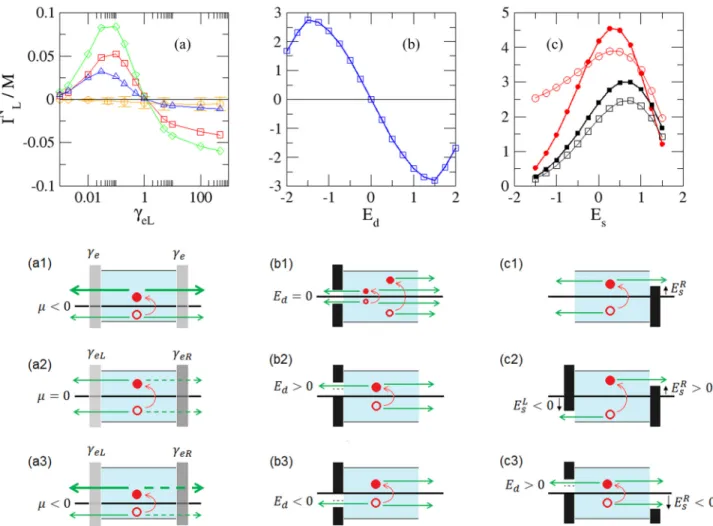
Indeed, if (i) is satisfied but not (ii), the contribution of the electronlike particles above μ and the contribution of the holelike particles below μ compensate each other on average, though each contribution taken separately is nonzero by virtue of (i). Hereafter, we discuss different implemen- tations of conditions (i) and (ii) and show evidence of the thermoelectric three-terminal ratchet effect in our setup. The effect is illustrated in Fig.2for different kinds of asymmetric contacts.
A. Asymmetric contacts as ratchet pawls
Condition (i) is implemented by inserting different contacts at the left and right NW extremities. Within the theoretical framework reviewed above, the contact between the NWs and the reservoirαis characterized by the couplingγeα. We focus on some specific choices for this metal-semiconductor contact:
(a) γeα(E)=γeα independent of the energy. This model, implemented via energy-independent tunnel barriers between NWs and electrodes, does not break electron-hole symmetry
FIG. 2. Illustration of the ratchet effect powered byδTP >0, for various types of contacts. The total particle currentILN [see Eq. (7)], obtained withδTp=10−3andδμ=0, is plotted (in units of 105/and divided byM) in top panels (a-c) for different configurations shown below (a1-c3) and listed at the end of Sec. III A. (Left) Energy-independent tunnel barriers. If the contacts are symmetric (a1) or ifμ=0 (a2),ILN =0 on average. If both symmetries are broken (a3) a net current is generated. (a)ILN/M as a function ofγeL (in units of/) for fixedγeR=/and various positions ofμ[μ/=0 (◦),−0.5 (),−1 ( ) and−2.5 ()]. (Middle) Energy filter. WhenEd=0 electron-hole symmetry makes the total current vanish (b1), whereasEd>0 (b2) andEd <0 (b3) correspond to negative and positive current, respectively.
(b)ILN/M atμ=0, for constantγeR=/on the right and an energy filter on the left withγe=/, opening=, and tunableEd (in units of). (Right) (c1) Single barrier configuration. The Schottky barrier prevents electron- and hole-like excitations with energy belowERs to escape to the right contact. (c2) Double barrier configuration. A low energy filter is added at the left contact, forbidding electron- and hole-like excitations with energy aboveEsLto tunnel leftward. (c3) Hybrid configuration. A Schottky barrier on the right is combined with an energy filter on the left. (c)ILN/Matμ=0, as a function of the barrier heightEs(in units of), withγe=/, for the single barrier (,Es≡EsR), double barrier (•,Es≡EsR= −EsL), and hybrid cases (Es ≡ERs) withEd=0 () andEd = −(◦).
[condition (ii)]. However, this can be easily done by putting the device in a field effect transistor configuration [33–35], so as to haveμ=0 (see Fig.2, left column).
(b) γeα(E)=γeα (E−Eαs), with the Heaviside (step) function. This is the simplest model for a Schottky barrier at the NW-reservoirαinterface, acting as anhigh energy filter—only charge carriers with energyEi above a certain thresholdEsα can flow [see Fig.2(c1)]. The barrier guarantees that condition (ii) is fulfilled.
(c) γeα(E)=γeα[1− (E−Esα)], i.e., a simple model for alow energy filter—only charge carriers with energyEibelow a certain thresholdEsαcan flow [see Fig.2(c2)]. Despite being more difficult to implement in practice, it offers an instructive toy model. Just as in the previous case, the barrier ensures that condition (ii) is satisfied.
(d) γeα(E)=γeαifE∈[Ed−/2,Ed+/2] and 0 else- where. This is a simple model for anenergy filter, allowing only charge carriers with energiesEinside a windowaround Ed to flow into/out of the NWs (see Fig.2, middle column).
In practice, it could be realized by embedding a single level quantum dot in each NW close to electrode α; would represent the dot opening, andEdits energy level, easy tunable with an external gate [40]. Even forμ=0 at the band center, this model fulfills condition (ii) if Ed =0. Moreover, for a large opening of the dot and a proper tuning of Ed, this model can mimic a low energy filter.
To fulfill requirement (i), it is necessary to introduce different coupling functions γeL(E)=γeR(E) to the left and right reservoirs. Hereafter, we consider the following asymmetric configurations:
(1) “Asymmetric tunnel contacts”: this is implemented by fabricating different energy-independent contacts γeL=γeR
[Fig.2(a3)].
(2) “Single filter”: an energy filter—withγeα(E)=γe if E∈[Ed−/2,Ed+/2] and 0 elsewhere—is placed on the left, and an energy-independent tunnel barrierγeR(E)=γeon the right [Figs.2(b2)and2(b3)].
(3) “Single barrier”: we consider an energy-independent tunnel barrier on the leftγeL(E)=γeand a Schottky barrier between the NWs and the right contact,γeR(E)=γe (E− EsR) [Fig.2(c1)].
(4) “Double barrier”: we consider a low energy filter on the left,γeL(E)=γe[1− (E−ELs)], and a Schottky barrier on the right,γeR(E)=γe (E−EsR) [Fig.2(c2)].
(5) “Hybrid configuration”: as the previous one, but with the left low energy filter replaced by an energy filter (an embedded quantum dot), with γeL(E)=γe if E∈[Ed− /2,Ed+/2] and 0 elsewhere [Fig.2(c3)]. This model is introduced as a refinement of the double barrier one, easier to implement experimentally.
B. Ratchet-induced charge current
Once the phonon bath is heated up (δTP >0), the NW electrons are driven out of equilibrium and electron-hole excitations are created around μ (see the corresponding sketches in Fig. 2). Knowing that the couplings γiα(Ei)= γeα(Ei) exp(−2xiα/ξ) and that the electronic states are uni- formly distributed along the NWs, we focus for simplicity on a single excitation at the NW center and discuss the phenomenology leading to a finite charge current generation in the different situations shown in Fig.2(the same reasoning can be extended on statistical grounds to the set ofNstates inside each NW). Our qualitative predictions (based on the simplified pictures sketched in the bottom panels of Fig.2) are confirmed by the numerical simulations which take all excitations into account (top panels of Fig.2).
The first column refers to the case of energy independent coupling factorsγeLandγeR. If they are equal (γeL=γeR) both electron- and holelike excitations have the same probability to tunnel out to the left/right reservoir, and no net current flows [Fig. 2(a1)]. Breaking this symmetry induces a preferential direction for tunneling out of the NW, thus fulfilling condition (i) [Fig. 2(a2)]. However, without electron-hole symmetry breaking [condition (ii)], the number of holelike excitations with energyμ−Eequals on average [60] that of electronlike ones with energy μ+E, resulting again in a vanishing current. This second symmetry can be broken by shifting the electrochemical potential μ within the NWs impurity band via a top/back gate [33,61] leading to μ=0. In this case, and providedγeL=γeR, a net current flows through the NW array [Fig.2(a3)]. The total particle current per NWILN/Mis shown in panel (a) as a function of the left couplingγeLfor fixedγeR and different positions of μin the impurity band.
Our qualitative analysis is confirmed: the current vanishes for μ=0 at the band center (at least within the error bars [62]), whereas it is nonzero forμ=0 onceγeL=γeR. The sign of ILN (taken positive when the flow of electrons goes from left to right) is given by the sign ofμ(γeL/γeR−1).
The middle column describes the effect of an energy filter of widthand couplingγe, centered atEd, and placed between the NWs and the left reservoir. In this caseμ=0 is fixed at the impurity band center, and at the right contactγeR(E)=γe. From the sketch we see that condition (i) is straightforwardly satisfied, whereas condition (ii) is fulfilled only if Ed =0.
Interestingly, it is possible to control the direction of the current by simply adjusting the position ofEd: ifEd >0 [Fig.2(b2)]
the electronlike excitation created above μ (within ) can tunnel left or right with equal probability, whereas the holelike one (within ) can only escape to the right. Other electron and hole excitations beyond the energy rangearoundμare equally coupled to the electrodes and do not contribute to the current. A net electric current is thus expected to flow leftward (ILN<0). By the same token, whenEd <0 [Fig.2(b3)] the holelike excitation (within ) does not contribute, whereas the electronlike one can tunnel right: We thus expect a finite current flowing rightward (ILN >0). All these predictions are confirmed in panel (b), in which we see that the average particle current exhibits asymmetric behavior with respect toEd.
Finally, the third column shows the effect of a single and a double barrier whenμ=0 is fixed. Let us begin with a single Schottky barrier on the right [Fig. 2(c1)]: The electron and hole excitations can tunnel out to the right only if their energy is higher than the barrier. Since holes are more blocked than electrons by the low energy filter whatever the value ofEsR, the current is expected to flow rightward (ILN >0). Moreover, recalling that the tunneling rates between the localized states and the electronic reservoirsL andR are given by Eq. (3), we infer that the dominant contributions to the current come from energy excitations roughly withinkBT aroundμ. As a consequence the net electric current is expected to increase until the barrier heightEs kBT aboveμ: This is confirmed by looking at the corresponding current plot (c). Fig. 2(c2) illustrates the double barrier case, focusing on the situation EsR = −EsL≡Es. The high energy filter acts on the left way out as the low energy filter acts on the right way out, upon inverting the role of electrons and holes. Since holes flowing leftward are equivalent to electrons going rightward, this results in an enhanced ratchet effect and thus a larger current, as shown in Fig.2(c). As in the single barrier case, the maximum current is expected and indeed found atEs kBT. The double barrier configuration ensures high performances, but is of difficult implementation. In Fig. 2(c3) we thus discuss the hybrid case, with an energy filter on the left, e.g., an embedded quantum dot close to the interface, and a single Schottky barrier on the right. Raising the barrier height increases the current, but now the filter position (Ed) plays a role in determining its value. The Ed=0 case is similar to the single barrier one, because we have assumed= > kBT, i.e., almost all relevant excitations are within, and hence coupled to the left reservoir as if there was no barrier at all. By similar arguments, the results for theEd= −case are closer to the double barrier one: in this case the states aboveEd+/2 are blocked as if there was a low energy filter.
The current plots in Fig.2show the ratchet effect to be much less pronounced for asymmetric tunnel contactsγeL=γeR. For this reason, when discussing the device performance we will focus on the other cases only.
-2 -1 0 1 2 Es 0
2 4 6
S
-2 -1 0 1 2
Es 0.001
0.01 0.1 1 10 100
ZT
-2 -1 0 1 2
Es 0
0.1 0.2
Q / M
FIG. 3. (Top) Nonlocal thermopower S (in units of kB/e), electronic figure of meritZT, and power factorQ(in units ofkB2/) in the single barrier (black line), double barrier (red line) and hybrid [withEd =0 () andEd = −(
◦
)] configurations. Data are plotted as functions of the (right) barrier height EsR≡Es (in units of).For the double barrier case,EsR= −EsL. For the hybrid one,=. (Bottom) S,ZT, andQ/M in the double barrier configuration as functions of the left and right barrier heightsEsLandERs (in units of ). In all panels,γe=/andμ=0.
IV. DEVICE PERFORMANCE FOR ENERGY HARVESTING AND COOLING
A. Nonlocal thermopower, figure of merit, and power factor We define a nonlocal thermopower [9] quantifying the voltage (δμ/e,e <0 electron charge) between the electronic reservoirsL andR due to the temperature difference (δTP) with the phonon bathP, in the absence of a temperature bias between the two electrodes (δT =0):
S= −δμ/e δTP
ILN=0= 1 e T
L13
L11. (10) Similarly, the nonlocal electronic [63] figure of meritZT and power factorQread
ZT =GlS2
(P)l T = L213 L11L33−L213,
(11) Q=GlS2= 1
T3 L213 L11,
where Gl=[eILN/(δμ/e)]|δT ,δTP=0=e2L11/T and (P)l = [IPQ/δTP]|IN
L=0=(L11L33−L213)/(T2L11) are local electrical and (electronic) thermal conductances [64]. Recall that the figure of merit ZT is enough to fully characterize the performance of a thermoelectric device in the linear response regime [55,65]: The maximum efficiency and the efficiency at maximum power (energy harvesting) and the coefficient of performance (cooling) can be expressed in terms ofZTand the Carnot efficiencyηC. The power factorQis instead a measure of the maximum output power that can be delivered by the device when it works as a thermal machine.
In Sec.IIIthree situations were discussed: the single barrier, the double barrier, and the hybrid case. Figure3, top panels,
show the nonlocal coefficients S, ZT, and Q in the three configurations, as functions of the right Schottky barrier height EsR ≡Es(a comparison with the local coefficients is provided in AppendixB). For the double barrier case, we have assumed EsR = −EsL, whereas for the hybrid case different choices for the centerEdof the left filter are specified in the figure. In all cases, the nonlocal thermopower increases monotonically with Es. Interestingly, the double barrier curve is exactly twice the single barrier one [66]. This can be understood by noticing that the two barriers at the right and left interfaces play the same role in filtering electrons and holes, respectively, and their effects add up. This idealized configuration offers the largest thermopower at largeEs. As a possible practical realization, we consider the hybrid configuration with a large openingof the dot and a proper tuning of the levelEd. WithEd = −, we find that the thermopower in the hybrid case reaches values (red circles in the top left panel) significantly larger than the single barrier one. However, even if at smallEs 0 this configuration is better than the ideal double barrier, it is not as performant at higherEs. On the other hand, we note that theEd =0 case is equivalent to the single barrier one [see Fig.2(b2)and related discussion].
The nonlocal electronic figure of merit increases very rapidly withEs. In particular, for the hybrid case it reaches substantial values, up toZT 10, halfway between the single barrier case (ZT 0.1) and the (ideal) double barrier one (ZT 102). Remarkably, the power factorQshows a similar behavior asZT: It increases with the Schottky barrier height at least up toEs kBT, and then starts decreasing. Just as for the particle current discussed previously and shown in Fig.2(c), this is because the NW states better coupled to the reservoirs are those withinkBT ofμ. Note that for the hybrid case, the value ofEs that maximizesZT is (almost) equal to the one maximizingQ: highZT ≈10 can be reached together with a good (scalable) power factor.
For completeness, we have also plotted in the bottom panels of Fig. 3 the nonlocal transport coefficients S, ZT, andQin a general double barrier configuration, as functions of the barriers heights EsL and EsR. Given our system, a symmetry with respect to the axisEsR = −EsL arises. Quite more remarkably, we observe a wide range of values ofERs and EsLfor which the electronic figure of merit and the power factor are simultaneouslylarge. In particular, in the regime where Q/M is maximum (aroundEsR =kBT =0.5= −EsL)ZT can reach values up to∼10.
B. Energy harvesting and cooling
In order to harvest power from the device, we apply a bias δμ <0 against the particle current. We focus on the regime where electrical power P = −δμILN >0 can be generated from waste heat (IPQ>0) from the hot substrate (δTP >0) under the condition of isothermal electronic reservoirs (δT = 0). This is a particular region of the phase diagram shown in Fig. 4(a), delimited by [40,65] δμstop < δμ <0 where δμstop≡ −eSδTP is the critical value at which the output power vanishes. By further decreasingδμ,Pbecomes negative and hence the harvester useless. Note thatδμstopis proportional to the thermopowerSplotted in the top left panel of Fig.3.
This implies in particular that the working regime range is
FIG. 4. (a) Phase diagram showing for which values ofδμ(in units of) andδTP(in units of/kB) the NW-based ratchet operates as an energy harvester or as a phonon bath refrigerator, given thatδT = 0. The plot is drawn for the hybrid configuration (withEd = −,= , andEsR=), the single and double barrier ones being qualitatively similar. (b) Heat-to-work conversion efficiencyη(normalized toηC) as function of the output power P (in units of2/) when δμis varied, at fixedδTP =10−3/kB. The three loops correspond to the single barrier (EsR=, black line), double barrier (EsR= −EsL=, red line), and hybrid [same as in (a), red dashed line] cases. The red dots highlight the values of the efficiency at maximum powerη(Pmax).
In both panels,μ=0 andγe=/.
broader in the double barrier case than in the single barrier one.
The heat-to-work conversion efficiencyηof the ratchet in this harvesting regime is simply given by [65]η= −δμILN/IPQ because here, and in all cases considered in this paper, IRQ<0 and ILQ<0. In Fig. 4(b), η is plotted as function of the output power P = −δμILN, upon varying δμ from 0 to δμstop, keepingδTP fixed. Whilst in the single barrier setup both efficiencies and output power are small, the double barrier and hybrid configurations allow to extract a much larger power with an efficiency up to 60% of the Carnot limitηC≡1−T /TP δTP/T. Notice also that the efficiency at maximum output power η(Pmax)—highlighted by the red dots in Fig. 4(b)—can reach values close to the Curzon-Ahlborn limit [65,67]ηCAηC/2. ConcerningPmax, we find that a value of P /M ≈4.10−82/ in Fig. 4(b), obtained with δTP =10−3/kB andγe=γep=/, corre- sponds toP /M ≈10−15W assuming /kB ≈100 K (hence δTP ≈0.1 K, andγe=γep≈1.3×10¹³s−1). Consequently, for an array of M=106 NWs and a larger temperature bias δTP ≈10 K, a maximum output power of the order of Pmax≈10μW can be envisaged [68]. Recall however that this is an “electronic” estimate. The fullηwill be decreased by parasitic phonon contributions here neglected.
Beside harvesting power, the device could also be used as a refrigerator of the phonon bath [31]. In this case δTP <0 and δμ >0: an electrical power δμILN >0 is invested to extract heatIPQ>0 from the (cold) substrate. The refrigerator working range is δμ > δμ(r)stop≡ −L33/(L13T)δTP. At the critical value δμ(r)stop the heat current from the phonon bath vanishes,IPQ=0. Fig.4(a)shows that the refrigerator working region (blue) is smaller than the harvesting one (red). Besides, the cooling efficiency of the ratchet is the coefficient of perfor- manceη(r) =IPQ/δμILN, characterized by the same electronic
figure of meritZT as in the energy harvesting case. Hence, though the double-barrier setup is once again the ideal one, the hybrid configuration allows to reachZT 10, making the NW-based ratchet a potentially high-performance cooler.
V. CONCLUSION
We have discussed the possible realization of a semi- conductor NW-based ratchet for thermoelectric applications, operating in the activated hopping regime. We have shown how to exploit spatial symmetry breaking at the contacts for the generation of a finite electric current through the NWs, and analyzed several ways in which this could be achieved. In particular the “hybrid configuration,” which could be implemented experimentally by embedding a quantum dot close to one contact and fabricating a Schottky barrier at the other one, can achieve simultaneously substantial efficiency, with an electronic figure of meritZT ∼10, and large (scalable) output power Q. A more realistic estimate of thefull figure of merit ZT would need to evaluate also the parasitic (phononic) contributions to the heat conductance [31] between the two electrodes and the substrate [69]. These would reduce the device performance, but their effect can be limited by suitably engineering the geometry of the setup [70–73]. All these considerations put forward the proposed NW-based ratchet as a simple, reliable, and high-performance thermoelectric setup, offering opportunities both for energy harvesting and for cooling.
Future developments of this paper may concern a time dependent control of the generated current. For instance, by acting with a time-varying gate potential on the energy filter levelEd [see Figs.2(b1),2(b2),2(b3), and2(c3)], one could arbitrarily tune the sign ofILN, thus exploiting the heat coming from the substrate to generate AC currents. More generally, the possibility of exploiting (further) ratchet effects due to time-dependent drivings could be explored [74].
ACKNOWLEDGMENTS
We thank S. Roddaro for fruitful comments and sugges- tions, and the STherQO members for inspiring discussions.
The work of R.B. has been supported by MIUR-FIRB2013 – Project Coca (Grant No. RBFR1379UX). C.G. acknowledges financial support from the Deutsche Forschungsgemeinschaft through SFB 689. C.G, G.F. and J.-L.P. acknowledge CEA for its support within the DSM-Energy Program (Project No.
E112-7-Meso-Therm-DSM).
APPENDIX A: TEMPERATURE EFFECTS
In this section we estimate the results’ dependence on the temperature. This issue was addressed in a previous work [34]
for a similar system under different conditions. The (nonlocal) coefficientsS,ZT, andQare plotted in Fig.5 for different kBT’s, in the hybrid configuration. The thermopower reaches higher values at small temperatures. However, in this regime the electrical conductance Gl is very small [33] and so is also the power factorQ=GlS2. This is evidence of the fact that the thermal energy kBT establishes how easy it is for a localized electron to hop toward another localized state in the (activated) hopping regime: IfkBT is too small, the
15 30 45
S
10-3 10-2 10-1 100 101 102
ZT
-1 0 1
ES 0
0.05 0.1 0.15
Q / M
FIG. 5. Nonlocal thermopower S (in units ofkB/e), electronic figure of meritZT and power factorQ(in units ofk2B/) for various temperatures [kBT /=0.05 (◦), 0.1 (), 0.5 ( ), and 1 ()]. Data are plotted for the hybrid configuration as functions of the (right) barrier heightEsR≡Es(in units of). Other parameters areEd = −, =,γe=/, andμ=0.
electrical conductance vanishes exponentially, reducing the power factor drastically. Furthermore, it is also known [33]
that increasing the temperature too much reduces Gl after some point, when all termsIij(k)andIiα(k), for each couple (i,j), (i,α) and NW k, tend to vanish, irrespective of the degree of left-right asymmetry. In the end, the best compromise for the power factor is found for an intermediate temperature kBT 0.5. Concerning the electronic figure of meritZT, its behavior withT much depends on the right barrier heightEs. It reaches its highest value forEs ≈0.5at low temperatures, but at this point the smallness of the power factor limits the device performance. Nevertheless, a good compromise can be found between efficiency and output power in the temperature rangekBT ≈0.1−1with a correct adjustment ofEs.
-2 0 2 4 6
S
10-4 10-2 100 102
ZT
-1 0 1
E
s 00.1 0.2
Q / M
FIG. 6. Nonlocal (full lines) versus local (dashed lines) transport coefficients, shown for the single barrier (black), double barrier (red), and hybrid (blue) configurations. Data are plotted as functions of the (right) barrier heightEsR≡Es (in units of). For the double barrier case,EsR= −EsL. For the hybrid one,Ed = −and=. The thermopowers and power factors are given in units ofkB/eand k2B/, respectively. In all panels,γe=/andμ=0.
APPENDIX B: LOCAL VS NONLOCAL TRANSPORT COEFFICIENTS
Our NW-based ratchet, in the configurations considered, boasts nonlocal transport coefficients typically larger than the local ones. The latter are defined forδTP =0 as:
Sl = − δμ eδT
ILN=0 = L12 e T L11,
ZTl = GlSl2
(L)l T = L212
L11L22−L212, (B1) Ql =GlSl2= 1
T3 L212 L11,
where Gl=[eILN/(δμ/e)]|δT ,δTP=0=e2L11/T and (L)l = [ILQ/δT]|IN
L=0=(L11L22−L212)/(T2L11) are local electric and (electronic) thermal conductances [9]. In Fig.6we show the local (dashed lines) and nonlocal (full lines) transport coefficients for the single barrier, double barrier, and hybrid
configurations. In all the cases, the nonlocal coefficients can reach larger values with respect to the corresponding local ones. Notice however that the local coefficients can be enhanced by probing band edge transport [33,34], which is an alternative route to the symmetry-breaking one followed here.
[1] A. F. Ioffe,Semiconductor Thermoelements and Thermoelectric Cooling(Infosearch, London, 1957).
[2] L. D. Hicks and M. S. Dresselhaus,Phys. Rev. B47, 12727 (1993).
[3] L. D. Hicks and M. S. Dresselhaus,Phys. Rev. B47, 16631 (1993).
[4] K. Saito, G. Benenti, G. Casati, and T. Prosen,Phys. Rev. B84, 201306(2011).
[5] D. S´anchez and L. Serra,Phys. Rev. B84,201307(2011).
[6] M. Horvat, T. Prosen, G. Benenti, and G. Casati,Phys. Rev. E 86,052102(2012).
[7] V. Balachandran, G. Benenti, and G. Casati,Phys. Rev. B87, 165419(2013).
[8] K. Brandner, K. Saito, and U. Seifert,Phys. Rev. Lett. 110, 070603(2013).
[9] F. Mazza, R. Bosisio, G. Benenti, V. Giovannetti, R. Fazio, and F. Taddei,New J. Phys.16,085001(2014).
[10] R. Bosisio, S. Valentini, F. Mazza, G. Benenti, R. Fazio, V.
Giovannetti, and F. Taddei,Phys. Rev. B91,205420(2015).
[11] R. S. Whitney,Phys. Rev. B87,115404(2013).
[12] P. Machon, M. Eschrig, and W. Belzig,Phys. Rev. Lett.110, 047002(2013).
[13] F. Mazza, S. Valentini, R. Bosisio, G. Benenti, V. Giovannetti, R. Fazio, and F. Taddei,Phys. Rev. B91,245435(2015).
[14] S. Valentini, R. Fazio, V. Giovannetti, and F. Taddei,Phys. Rev.
B91,045430(2015).
[15] R. S´anchez and M. B¨uttiker,Phys. Rev. B83,085428(2011).
[16] A. N. Jordan, B. Sothmann, R. S´anchez, and M. B¨uttiker,Phys.
Rev. B87,075312(2013).
[17] B. Sothmann, R. S´anchez, A. N. Jordan, and M. B¨uttiker,New J. Phys.15,095021(2013).
[18] B. Roche, P. Roulleau, T. Jullien, Y. Jompol, I. Farrer, D. Ritchie, and D. Glattli,Nat. Commun.6,6738(2015).
[19] F. Hartmann, P. Pfeffer, S. H¨ofling, M. Kamp, and L. Worschech, Phys. Rev. Lett.114,146805(2015).
[20] H. Thierschmann, F. Arnold, M. Mitterm¨uller, L. Maier, C.
Heyn, W. Hansen, H. Buhmann, and L. W. Molenkamp,New J.
Phys.17,113003(2015).
[21] P. P. Hofer and B. Sothmann, Phys. Rev. B 91, 195406 (2015).
[22] R. S´anchez, B. Sothmann, and A. N. Jordan,Phys. Rev. Lett.
114,146801(2015).
[23] B. Rutten, M. Esposito, and B. Cleuren,Phys. Rev. B80,235122 (2009).
[24] T. Ruokola and T. Ojanen,Phys. Rev. B86,035454(2012).
[25] C. Bergenfeldt, P. Samuelsson, B. Sothmann, C. Flindt, and M.
B¨uttiker,Phys. Rev. Lett.112,076803(2014).
[26] B. Cleuren, B. Rutten, and C. Van den Broeck,Phys. Rev. Lett.
108,120603(2012).
[27] A. Mari and J. Eisert,Phys. Rev. Lett.108,120602(2012).
[28] O. Entin-Wohlman, Y. Imry, and A. Aharony,Phys. Rev. B82, 115314(2010).
[29] J.-H. Jiang, O. Entin-Wohlman, and Y. Imry,New J. Phys.15, 075021(2013).
[30] O. Entin-Wohlman, Y. Imry, and A. Aharony,Phys. Rev. B91, 054302(2015).
[31] J.-H. Jiang, O. Entin-Wohlman, and Y. Imry,Phys. Rev. B85, 075412(2012).
[32] J.-H. Jiang, M. Kulkarni, D. Segal, and Y. Imry,Phys. Rev. B 92,045309(2015).
[33] R. Bosisio, C. Gorini, G. Fleury, and J.-L. Pichard,New J. Phys.
16,095005(2014).
[34] R. Bosisio, C. Gorini, G. Fleury, and J.-L. Pichard,Phys. Rev.
Appl.3,054002(2015).
[35] R. Bosisio, C. Gorini, G. Fleury, and J.-L. Pichard,Physica E:
Low-dimensional Systems and Nanostructures74,340(2015).
[36] J. P. Pekola and F. W. J. Hekking,Phys. Rev. Lett.98,210604 (2007).
[37] J.-H. Jiang, O. Entin-Wohlman, and Y. Imry,Phys. Rev. B87, 205420(2013).
[38] Z. Li, Q. Sun, X. D. Yao, Z. H. Zhu, and G. Q. M. Lu,J. Mater.
Chem.22,22821(2012).
[39] J. Kim, J.-H. Bahk, J. Hwang, H. Kim, H. Park, and W. Kim, Phys. Status Solidi RRL7,767(2013).
[40] N. Nakpathomkun, H. Q. Xu, and H. Linke,Phys. Rev. B82, 235428(2010).
[41] A. I. Hochbaum, R. Chen, R. D. Delgado, W. Liang, E. C.
Garnett, M. Najarian, A. Majumdar, and P. Yang, Nature (London)451,163(2008).
[42] A. I. Persson, L. E. Fr¨oberg, L. Samuelson, and H. Linke, Nanotechnology20,225304(2009).
[43] M. C. Wang and B. D. Gates,Materials Today12,34(2009).
[44] B. M. Curtin, E. W. Fang, and J. E. Bowers,J. Electron. Mater.
41,887(2012).
[45] R. A. Farrell, N. T. Kinahan, S. Hansel, K. O. Stuen, N. Petkov, M. T. Shaw, L. E. West, V. Djara, R. J. Dunne, O. G. Varona, P. G.
Gleeson, J. S.-J, H.-Y. Kim, M. M. Kole´snik, T. Lutz, C. P.
Murray, J. D. Holmes, P. F. Nealey, G. S. Duesberg, V. Krsti´c, and M. A. Morris,Nanoscale4,3228(2012).
[46] A. Stranz, A. Waag, and E. Peiner,J. Electron. Mat.42,2233 (2013).
[47] E. C. Garnett, M. L. Brongersma, Y. Cui, and M. D. McGehee, Annu. Rev. Mater. Res.41,269(2011).
[48] R. R. LaPierre, A. C. E. Chia, S. J. Gibson, C. M. Haapamaki, J. Boulanger, R. Yee, P. Kuyanov, J. Zhang, N. Tajik, N. Jewell, and K. M. A. Rahman,Phys. Status Solidi (RRL)7,815(2013).
[49] K.-I. Chen, B.-R. Li, and Y.-T. Chen,Nano Today6,131(2011).
[50] N. F. Mott,Phil. Mag.19,835(1969).
[51] V. Ambegaokar, B. I. Halperin, and J. S. Langer,Phys. Rev. B 4,2612(1971).
[52] A. Rahman, M. K. Sanyal, R. Gangopadhayy, A. De, and I. Das, Phys. Rev. B73,125313(2006).
[53] H. Linke, T. E. Humphrey, A. L¨ofgren, A. O. Sushkov, R.
Newbury, R. P. Taylor, and P. Omling,Science286,2314(1999).
[54] S. Sassine, Y. Krupko, J.-C. Portal, Z. D. Kvon, R. Murali, K. P.
Martin, G. Hill, and A. D. Wieck, Phys. Rev. B78,045431 (2008).
[55] H. Callen,Thermodynamics and an Introduction to Thermostat- ics(John Wiley and Sons, New York, 1985).
[56] In previous works [33–35] focusing on band-edge transport, the energy dependence of the localization length was crucial and thus taken into account. Such dependence is here largely inconsequential: Apart from a brief discussion of the less relevant configuration of Figs.2(a1),2(a2), and2(a3), the band edges will not be probed.
[57] A. Miller and E. Abrahams,Phys. Rev.120,745(1960).
[58] It is indeed close to the Mott temperature kBTM=2/ξ ν= 2 and much larger than the activation temperature kBTx= ξ /(2νN2)=8.10−4(see Ref. [33] for more details).
[59] R. P. Feynman, B. R. Leighton, and M. Sands,The Feynman Lectures on Physics(Addison-Wesley, Redwood, CA, 1964), Vol. 1.46.
[60] It is worth stressing that if we consider a single NW, electron- hole symmetry may be broken even atμ=0 due to disorder;
however, when considering a large set of NWs having constant density of statesν, symmetry is restored on average.
[61] R. Bosisio, G. Fleury, and J.-L. Pichard,New J. Phys.16,035004 (2014).
[62] They give an estimation of the difference between data obtained for finiteMand the quantityILN/MforM→ ∞.
[63] We refer to the “electronic” figure of meritZT to distinguish it from the “full” figure of meritZT, which would include also the phononic contributions to the thermal conductance, here neglected.
[64] These coefficients are all special instances of the more general ones discussed in Ref. [9].
[65] G. Benenti, G. Casati, T. Prosen, and K. Saito,arXiv:1311.4430.
[66] Switching from the single barrier configuration to the double barrier configuration, the Onsager coefficientL13 is increased whileL11is decreased, in such a way that the ratioL13/L11is exactly doubled for any value ofEs.
[67] F. Curzon and B. Ahlborn,Am. J. Phys.43,22(1975).
[68] It is also interesting to give an estimation of the reachable output power density. It depends on the geometric parameters of the NW array. They must be chosen so as to be consistent with the experimental constraints and with the 1D model used in this work (typically, the NW diameter needs to be smaller than the Mott hopping length [33]LM ≈√
ξ /(2νkBT)≈4a). Also, since the reported results are mostly independent of the NW lengthLas long asLLM is long enough to be in the Mott hopping regime, choosing a shortLis preferable. By considering for instance a NW diameter of 20nm and a packing density of 20%,M=105NWs can be stacked in parallel along a 1cm wide chip, yieldingPmax≈1W (keeping the same model parameters as right above). Taking 1m-long NWs, this gives an output power density of the order of 10mW/cm2.
[69] Additional heat exchanges between the substrate phonons and the electrodes could take place via direct contact be- tween them, or via phonon-mediated processes involving NWs phonons.
[70] R. Venkatasubramanian,Phys. Rev. B61,3091(2000).
[71] J.-S. Heron, C. Bera, T. Fournier, N. Mingo, and O. Bourgeois, Phys. Rev. B82,155458(2010).
[72] J.-K. Yu, S. Mitrovic, D. Tham, J. Varghese, and J. R. Heath, Nat. Nanotechnology5,718(2010).
[73] Y. He and G. Galli,Phys. Rev. Lett.108,215901(2012).
[74] S. Denisov, S. Flach, and P. H¨anggi, Phys. Rep. 538, 77 (2014).
![FIG. 5. Nonlocal thermopower S (in units of k B /e), electronic figure of merit ZT and power factor Q (in units of k 2 B /) for various temperatures [k B T / = 0.05 ( ◦ ), 0.1 ( ), 0.5 ( ), and 1 ( )]](https://thumb-eu.123doks.com/thumbv2/1library_info/5285282.1676420/8.911.514.797.102.734/nonlocal-thermopower-units-electronic-figure-factor-various-temperatures.webp)
