• Keine Ergebnisse gefunden

MichalTesaˇr TopQuarkThresholdScanandStudyofDetectorsforHighlyGranularHadronCalorimetersatFutureLinearColliders P ¨ M -P -I T U M¨ ¨

N/A
N/A
Protected

Academic year: 2021

Aktie "MichalTesaˇr TopQuarkThresholdScanandStudyofDetectorsforHighlyGranularHadronCalorimetersatFutureLinearColliders P ¨ M -P -I T U M¨ ¨"

Copied!
200
0
0

Wird geladen.... (Jetzt Volltext ansehen)

Volltext

(1)

T ECHNISCHE U NIVERSIT AT ¨ M ¨ UNCHEN

M AX -P LANCK -I NSTITUT

F UR ¨ P HYSIK

Dissertation in Physics

Top Quark Threshold Scan and Study of Detectors for Highly Granular Hadron Calorimeters at Future Linear Colliders

Michal Tesaˇr

(2)
(3)

T ECHNISCHE U NIVERSIT AT ¨ M ¨ UNCHEN

M AX -P LANCK -I NSTITUT F UR ¨ P HYSIK

Top Quark Threshold Scan and Study of Detectors for Highly Granular Hadron Calorimeters at Future Linear Colliders

Michal Tesaˇr

Vollst¨andiger Abdruck der von der Fakult¨at f ¨ur Physik der Technischen Universit¨at M ¨unchen zur Erlangung des akademischen Grades eines

Doktors der Naturwissenschaften (Dr. rer. nat.) genehmigten Dissertation.

Vorsitzender: Univ.-Prof. Dr. rer. nat. Martin Beneke Pr ¨ufer der Dissertation: 1. Hon.-Prof. Allen C. Caldwell, Ph. D.

2. Univ.-Prof. Dr. rer. nat. Laura Fabbietti

Die Dissertation wurde am 16.12.2013 bei der Technischen Universit¨at M ¨unchen einge-

reicht und durch die Fakult¨at f ¨ur Physik am 11.3.2014 angenommen.

(4)
(5)

I assure the single handed composition of this dissertation only supported by declared resources.

Munich, December 16, 2013 Michal Tesaˇr

(6)
(7)

Abstract

Two major projects for future linear electron-positron colliders, the International Lin- ear Collider (ILC) and the Compact Linear Collider (CLIC), are currently under develop- ment. These projects can be seen as complementary machines to the Large Hadron Collider (LHC) which permit a further progress in high energy physics research. They overlap con- siderably and share the same technological approaches. To meet the ambitious goals of precise measurements, new detector concepts like very finely segmented calorimeters are required.

We study the precision of the top quark mass measurement achievable at CLIC and the ILC. The employed method was a t t ¯ pair production threshold scan. In this technique, simulated measurement points of the t t ¯ production cross section around the threshold are fitted with theoretical curves calculated at next-to-next-to-leading order. Detector effects, the influence of the beam energy spectrum and initial state radiation of the colliding par- ticles are taken into account. Assuming total integrated luminosity of 100 fb 1 , our results show that the top quark mass in a theoretically well-defined 1S mass scheme can be ex- tracted with a combined statistical and systematic uncertainty of less than 50 MeV.

The other part of this work regards experimental studies of highly granular hadron calorimeter (HCAL) elements. To meet the required high jet energy resolution at the future linear colliders, a large and finely segmented detector is needed. One option is to assemble a sandwich calorimeter out of many low-cost scintillators read out by silicon photomul- tipliers (SiPM). We characterize the areal homogeneity of SiPM response with the help of a highly collimated beam of pulsed visible light. The spatial resolution of the experiment reach the order of 1 µ m and allows to study the active area structures within single SiPM microcells. Several SiPM models are characterized in terms of relative photon detection efficiency and probability crosstalk at the mentioned precision level.

The second experimental study investigates properties of plastic scintillators for an HCAL.

Light collection homogeneity of square scintillator tiles with an area of a few cm 2 and a

few mm in thickness is probed with a collimated electron beam from a radioactive 90 Sr

source. The same experimental apparatus is used to quantify the light crosstalk between

two neighboring scintillator cells. Two tile designs are tested and a high degree of homo-

geneity and low crosstalk level is demonstrated for one of the samples. Additionally, the

sensitivity of the scintillators to neutrons is tested by irradiating the tiles with a 241 Am/Be

neutron source. A substantial neutron sensitivity even with spectroscopic capabilities is

observed. This measurement is compared with Monte Carlo simulation. A good agree-

ment is demonstrated. It confirms that the experiment can be realistically described by

taking into account only basic physical processes.

(8)
(9)

CONTENTS

Preface 1

I. Introduction and Motivation 5

1. Standard Model of Particle Physics 7

1.1. Introduction . . . . 7

1.2. Higgs Mechanism . . . . 9

1.3. Shortcomings of the Standard Model . . . . 10

1.3.1. Supersymmetry . . . . 11

1.4. The Top Quark . . . . 12

1.4.1. Role of the Top Quark in the Standard Model . . . . 12

1.4.2. Mass Definitions . . . . 13

1.4.3. Mass Measurement Methods . . . . 14

2. Future Linear Colliders 15 2.1. Motivation for a Linear e + e Collider . . . . 15

2.2. Physics Potential . . . . 17

2.3. Accelerator Concepts . . . . 19

2.3.1. Compact Linear Collider . . . . 19

2.3.2. International Linear Collider . . . . 20

2.4. Detector Systems . . . . 22

2.4.1. International Large Detector . . . . 22

2.4.2. Silicon Detector . . . . 25

2.5. Detector Requirements . . . . 25

2.5.1. Particle Flow . . . . 26

2.5.2. Timing Requirements at CLIC . . . . 27

3. Silicon Photomultipliers 29 3.1. Basic Layout and Working Principle . . . . 29

ix

(10)

Contents

3.1.1. Quench Resistor . . . . 31

3.2. Gain . . . . 33

3.3. Photon Detection Efficiency . . . . 34

3.4. Signal Response Function and Saturation . . . . 35

3.5. Dark Noise and Afterpulsing . . . . 36

3.6. Optical Crosstalk . . . . 37

3.7. Temperature Effects and Light Intensity Measurement . . . . 38

II. Technology for Future Linear Colliders 39 4. Silicon Photomultiplier Homogeneity Studies 41 4.1. Photon-Emission Measurement . . . . 42

4.2. Experimental Apparatus . . . . 43

4.3. Data Analysis . . . . 46

4.3.1. Measurement Data . . . . 46

4.3.2. Coincidence Distribution and Noise Subtraction . . . . 47

4.3.3. Crosstalk and Pure 1 p.e. Maps . . . . 48

4.3.4. Analysis of Single Pixels . . . . 49

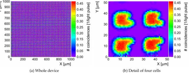
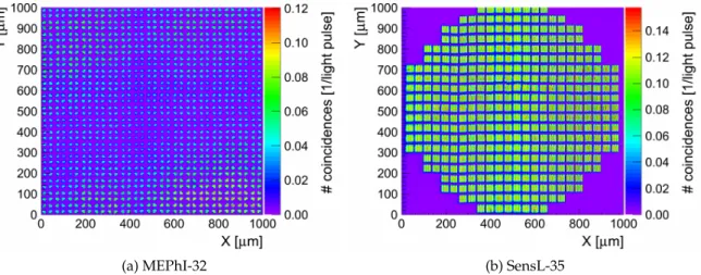
4.4. Results . . . . 52

4.4.1. Hamamatsu Multi-Pixel Photon Counters . . . . 52

4.4.2. Silicon Multi-Pixel Light Sensors . . . . 56

4.4.3. MEPhI and SensL Devices . . . . 60

4.5. Summary . . . . 61

5. Scintillator Tile Studies 63 5.1. Detector Layout . . . . 64

5.1.1. Scintillator . . . . 64

5.1.2. Silicon Photomultiplier . . . . 65

5.1.3. Light coupling . . . . 66

5.2. Readout System . . . . 68

5.3. Tests with β -Source . . . . 69

5.3.1. Experimental Apparatus . . . . 69

5.3.2. β -Source Properties . . . . 71

5.3.3. Trigger Configuration . . . . 72

5.4. Neutron Irradiation . . . . 74

5.4.1. Experimental Apparatus . . . . 75

5.4.2. Neutron Source Properties . . . . 75

5.4.3. Trigger Configuration . . . . 76

5.5. Data Analysis Tools . . . . 78

5.5.1. Experimental data . . . . 78

5.5.2. First Stage: Data Calibration . . . . 79

5.5.3. Second Stage: Calibrated Data Analysis . . . . 80

5.6. Results . . . . 83

5.6.1. Two-Dimensional Tile Scans . . . . 83

5.6.2. Crosstalk Scans . . . . 86

x

(11)

Contents

5.6.3. Neutron Irradiation . . . . 89

5.7. Summary . . . . 93

III. Precise Top Quark Mass Measurement at Future Linear Colliders 95 6. Precise Top Quark Mass Measurement at Future Linear Colliders 97 6.1. Top Quark Identification and Reconstruction . . . . 98

6.1.1. Key Physical Processes and Event Generation . . . . 98

6.1.2. Top Quark Reconstruction . . . 100

6.2. Top Quark Threshold Scan Simulation . . . 102

6.2.1. Calculation of the t t ¯ Production Cross Sections . . . 103

6.2.2. Corrections of the Cross Section . . . 104

6.2.3. Simulation of Data Points . . . 107

6.2.4. Template Fit . . . 109

6.3. Results . . . 114

6.3.1. Influence of Simulation Input Parameters . . . 114

6.3.2. Single m t Fit . . . 116

6.3.3. Simultaneous m t and α s Fit . . . 118

6.4. Top Quark Pole Mass . . . 121

6.5. Summary . . . 122

Conclusions 125 Acknowledgements 129 Appendix 133 A. Lists of Used Experimental Equipment 133 B. Silicon Photomultiplier Measurement Summary 137 B.1. Relative PDE and Crosstalk Maps . . . 137

B.2. Single Pixel Analysis Plots and Coincidence Distributions . . . 152

B.3. Photo-Emission Images Overlaid with SiPM Photographs . . . 160

B.4. Photographs of SiPM . . . 162

C. Top Quark Mass Measurement Summary 165 C.1. Two-Dimensional Template Fit Contour Plots . . . 165

C.2. Complete Result Summary of One-Dimensional Template Fit . . . 166

C.3. Complete Result Summary of Two-Dimensional m t and α s Template Fit . . . 169

Bibliography 175

List of Figures 183

List of Tables 187

xi

(12)
(13)

PREFACE

The subject of particle physics is to study, understand and mathematically describe matter at subatomic scales. This comprises investigations of radiation, elements of matter itself and interactions between these constituents. A theoretical framework of particle physics was gradually developed, confronted with experimental reality and extended. A global scientific effort resulted in the second half of the 20th century in an extraordinarily suc- cessful theory called the Standard Model of particles physics. The last few decades of experimental research up to the present day are dedicated to confirm or disprove predic- tions and calculations based on the Standard Model. In spite of all the success of the theory, there are some inconsistencies with the observed physical reality. This leads to a further urge for theoretical extensions on one hand and experimental guidance by discoveries on the other hand. Highly precise measurements are one of the aims of particle accelerator ex- periments. A contemporary particle accelerator which is providing the most accurate data so far is the Large Hadron Collider (LHC) at CERN. Despite its great performance and the recent success of discovering a new particle which is likely the Higgs boson, a lepton col- lider experiment is in general capable of achieving an even better precision. A construction of a new lepton collider together with continual improvements of experimental methods and technology can contribute a lot to deepen our understanding of this material world.

There are two major future e + e accelerator projects which are meant to be complemen- tary machines to the LHC. These are the International Linear Collider (ILC) and the Com- pact Linear Collider (CLIC). Even though there are some significant differences between the two, many parts of the projects overlap and share the same technological approaches.

The goal of this thesis is to contribute to the ongoing research and development effort which will at the end results in a high-performance particle accelerator experiment. There are many aspects of such a project which have to be studied and prepared. In this work, we address two different topics with one common underlying connection.

Top quark physics is one of the important field of study at the LHC and also at future linear colliders (FLC). We present a simulation-based study of the FLC capability to per- form precise measurements of the top quark mass. We determine the mass by using a threshold scan. It is based on the measurement of the t ¯ t pair production cross section in e + e collisions in the vicinity of the threshold. The top mass itself was obtained from a

1

(14)

Preface

template fit of the cross section data. The study included also further unwanted physics and detector effects on the measurement. Statistical and systematic uncertainties of the top 1S mass determination at CLIC and the ILC were calculated and represent together the total uncertainty of the measurement. The strong coupling constant was also extracted by the template fit and its precision is presented as well.

A high jet energy resolution of a collider experiment is a crucial parameter for reaching a satisfactory top quark identification efficiency. To meet the desired precision, a completely new hadron calorimeter concept is required. A new technological approach needs also development on the hardware level. Characterization of elements of prototype hadron calorimeter units is the second topic presented in this thesis. An FLC will employ highly granular hadron sandwich calorimeters. One option for the active calorimeter part are plastic scintillators. In this case, a single cell must have a volume of just a few cm 3 . To maintain compactness of the detector, usage of photomultiplier tubes is excluded. They must be replaced by much smaller silicon photomultipliers (SiPM). The areal homogene- ity of SiPMs response was investigated in the first part of the technical studies. The ho- mogeneity was probed by a highly collimated pulsed visible light beam. The spatial res- olution of the experiment allowed to observe active area structures within single SiPM microcells. Hamamatsu Multi-Pixel Photon Counters (MPPC) were the main subject of interest.

The second studied element of the calorimeter units were the scintillators. The plastic scintillators in the calorimeter are square-shaped tiles and the scintillation light is read out from one side by a SiPM. Areal light collection homogeneity of the scintillator tiles was investigated with a collimated electron beam from a radioactive source. This method al- lows to characterize and compare different tile designs. Additionally, the sensitivity of the scintillator to neutrons was tested by irradiation of the tiles with a radionuclide neu- tron source. Our study was motivated by differences observed by the Tungsten Timing Test-Beam experiment experiment in the response of a calorimeter with steel and tungsten absorbers. This points to the importance of understanding neutron detection in hadron calorimeters.

This thesis is divided into three parts which logically separate the theoretical and in- troductory, experimental, and physics-simulation dedicated chapters. First, we give an overview of the Standard Model. The symmetry concepts of the theory and the Higgs mechanism are explained. Some shortcomings of the construction which are leading the scientists to introduce further extension like the Supersymmetry and which are putting completeness of the Standard Model into question are also addressed in chapter 1.

Chapter 2 gives an introduction to the topic of future linear colliders. It mentions the physics motivation of a new accelerator experiment as well as technical aspects of the machine. Possible choices of accelerating technology for the colliders are discussed. We also summarize the important parameters of the detector systems.

Information about the basic properties of silicon photomultipliers is given in chapter 3.

The details of SiPM construction and operation are explained. Further, we present different options of quench resistor implementation. Impacts of operating conditions of the sensor and possible performance deterioration are described.

In chapter 4, we present the study of SiPMs. The areal response homogeneity of several

2

(15)

Preface

SiPM types was investigated with the main emphasis on Hamamatsu MPPCs. The techni- cal aspects of the experimental apparatus and measurement data analysis are described in detail. Finally, the results are discussed. The complete results of SiPM measurements are summarized in appendix B.

The characterization studies of plastic scintillators are presented in chapter 4. Technical details of used experimental setups are given as well as a description of the analysis tech- niques. The characteristics and performance of two different scintillator tile materials and designs are compared and discussed. The experimental results of the neutron irradiation are also confronted with a Monte Carlo simulation.

In chapter 6, the simulation of the top quark threshold scan at CLIC and the ILC is presented. The data simulation and analysis process is described in detail. Several sources of systematic uncertainties like ambiguities in background level, strong coupling constant and theoretical cross section calculation are addressed. The simulation was performed for the top pole and 1S mass scheme with the focus on results for the 1S mass definition. The full summary of top mass measurement simulation results is shown in appendix C.

Lists of experimental equipment with some technical details are summarized in ap- pendix A.

Parts of this thesis were already published in references [1] and [2].

3

(16)
(17)

Part I.

Introduction and Motivation

(18)
(19)

CHAPTER 1

STANDARD MODEL OF PARTICLE PHYSICS

The Standard Model of particle physics (SM) is the central theory of particles of the present day. It is a quantum field theory which describes all known elementary particles and three of the four known fundamental physical forces of the nature: the strong, the weak and the electromagnetic. The contemporary form of the SM has been established in the 70’s of the 20th century. Since then, it has had major success in describing experimentally observed phenomena and predicting existence of further particles. The past predictions of particles were based on symmetry considerations. The ν τ , the b, c and t quarks and the W and Z bosons were forecast this way and experimentally discovered later on. In the year 2012, another outstanding breakthrough has been achieved by the Large Hadron Collider (LHC) at the European Organization for Nuclear Research (CERN 1 ) when the ATLAS [3] and the CMS [4] collaborations announced the discovery of a boson compatible with the Standard Model Higgs boson [5, 6] which is also predicted. However, the SM has some issues. For example, it cannot predict masses of elementary particles from first principles, it does not include gravity and it cannot explain dark matter and dark energy which form 95 % of

“visible” universe. The Standard Model and its shortcomings will be discussed in this chapter.

1.1. Introduction

The SM is mathematically described by a scalar Lagrange density function (shortly La- grangian). It is generally based on Yang-Mills Theory [7, 8] which requires invariance of the Lagrangian under local gauge transformations (up to constant terms). These transfor- mations are in this case given by a representation of a special unitary gauge group SU(n) of degree n N and have a general form

1

The abbreviation “CERN” originates from the french name “Conseil europ´een pour la recherche nucl´eaire.”

7

(20)

1. Standard Model of Particle Physics

ψ → exp( − iα a (x) · T a ) ψ, (1.1)

where ψ is a field to be transformed, α a (x) are real functions of a continuous parameter x, a { 1 , 2 , . . . , n 2 − 1 } , and T a are Hermitian operators which form a basis of a vector space with dimension n 2 − 1 [9]. Because these gauge transformations form a group which is isomorphic to SU(n), T a are called group generators. The α a (x) are named gauge functions.

The symmetry of the Standard Model Lagrange density that matches experimental ob- servations is

U Y (1) × SU W (2) × SU C (3) . (1.2)

The U Y (1) symmetry is used instead of SU(1) because SU(1) is a trivial group with only one element. The meaning of the indices will be explained later on. The Lagrangian sym- metry (1.2) is assured in the following way:

In the Yang-Mills theory, it appears that the Dirac Lagrangian is generally not gauge invariant. To fix this issue, additional massless so called gauge fields must be introduced in the Lagrange density [10]. The number of these new fields is equal to the dimension of the particular transformation group. As a consequence of the gauge invariance and pres- ence of the gauge fields, a new term describing interaction between the fermionic gauge field arises. Furthermore, another self-interaction term appears for the SU(2) and SU(3) gauge group. It describes the interaction of the gauge fields themselves. These newly added fields are interpreted as bosons mediating a particular interaction between respec- tive fermions in quantum theory. They are named gauge bosons.

The group U Y (1) reflects the symmetry of the weak hypercharge and gives rise to one gauge boson B µ . The SU W (2) is the symmetry of the weak isospin and because the SU(2) group has three generators, this gauge introduces three further bosons, W µ 1 , W 2 µ and W µ 3 . The symmetry U Y (1) × SU W (2) describes the electroweak interaction, however none of the B µ and W i µ (i { 1, 2, 3 } ) bosons is a physical particle. Linear combinations of these form the photon, W ± and Z bosons. The SU C (3) gauge group represents the symmetry of color charge and describes the strong interaction mediated by eight gauge bosons called gluons.

The so far presented model comprises six fermions and twelve bosons. It is schemat- ically depicted in figure 1.1. The fermions form matter and can be further divided into quarks, which are subjected to all interactions, and leptons, which do not interact strongly.

Moreover, the explicit mass terms in the Dirac Lagrangian would violate the SU W (2) gauge invariance. Thus, they must be dropped. However, there is one major issue in the theory which contradicts experimental reality: all of the particles are massless. This problem is solved by the Higgs mechanism.

8

(21)

1.2. Higgs Mechanism

u c t d s b

e τ

ν e μ

ν μ ν τ W Z γ g

Str ong for ce Electr omag. f .

H

W eak for ce

Fermions Bosons

Quark s Leptons

I II III

Generation Force

carriers

Mass giving

Figure 1.1.: Overview of Standard Model particles and forces.

1.2. Higgs Mechanism

Since the explicit mass terms violate the gauge invariance, they obviously cannot be used and the masses of the particles must be generated differently. This can be done by a rather complicated procedure which starts by introducing a new complex scalar two-component field φ into the SM Lagrangian. The field φ has a potential

V(φ) = − µ 2 φ φ + λ 2 φ φ 2

, (1.3)

where µ, λ R + . It is required that the Lagrangian including the new field φ is invariant under U Y (1) × SU W (2) gauge. In a perturbation theory, particle interactions are described in terms of deviations from the vacuum ground state with the minimal energy. However, the potential (1.3) has a non-zero vacuum expectation value. Its depiction in two dimensions has the form shown in figure 1.2. Thanks to a proper redefinition of the field φ , so that per- turbation series can be expanded around the minimum of the potential, the gauge bosons acquire mass. However, the field φ intrinsically includes four bosons. Three of them are massless and have unphysical coupling terms to the gauge bosons in the Lagrangian. They are called Goldstone bosons and they can be removed by a proper choice of a specific gauge function (defined in equation (1.1)) [11]. The fourth boson in φ is massive and its name is the Higgs boson [12].

As a consequence of this procedure, called the Higgs mechanism [13, 14, 15], the gauge bosons induced by U Y (1) × SU W (2) symmetry have acquired mass and a neutral scalar massive particle represented by a new Higgs field has appeared. One should keep in mind that the physical weak bosons and the photon are obtained by linear combinations of the unphysical gauge bosons in the Lagrangian. This leads to massive W ± and Z bosons and a massless photon. The fermions acquire their masses through interaction with the Higgs

9

(22)

1. Standard Model of Particle Physics

V(Φ) = − µ 2 Φ 2 + λ 2 Φ 4

Φ

√ µ

µ 2λ 2λ

Figure 1.2.: Example of the Higgs potential in one dimension. Taken from [18].

field in further Yukawa terms which must be explicitly added to the SM Lagrangian [16, 17]. In the step where the field φ was redefined, the U Y (1) × SU W (2) symmetry has been broken to U Q (1), the symmetry of electromagnetism. Therefore, the Higgs mechanism is also called spontaneous symmetry breaking.

1.3. Shortcomings of the Standard Model

The Standard Model includes all known elementary particles and accurately describes most observations in particle physics today. However, the SM does not include gravity.

In addition, there are phenomena which are not described by the SM and some SM calcu- lations have to be treated very carefully to match the experimental results. Below, the most significant open issues of the SM will be addressed.

Dark matter and dark energy can be neither explained nor described by the SM at all.

From measurements of tangential rotational velocities of galaxies (dark matter) [19] and universe expansion speed (dark energy), the existence of these subjects of unknown nature is implied. Since about 70 % of the universe consists of dark energy, 25 % of dark matter and only 5 % of the Standard Model particles, the SM evidently fails in giving a complete picture of the particles making up the material part of this world.

Assuming that equal amounts of matter and anti-matter were created during the Big Bang and facing the fact that the known universe is composed exclusively of matter, there must be some effect which caused this imbalance. The solution could be CP violation of the SM. However, it is not large enough [20] to explain the matter-antimatter asymmetry.

Moreover, the neutrinos in the SM are massless. The discovery of neutrino oscillations [21, 22] implies that at least two of the three SM neutrinos must be massive.

Another issue of the SM is the hierarchy problem. It was experimentally observed that the value of µ from equation (1.3) is roughly of the order of 100 GeV [23]. The problem is

10

(23)

1.3. Shortcomings of the Standard Model

that µ receives quantum corrections from the virtual effects of every particle that couples to the Higgs field. For example, a fermion f coupling to the Higgs field H leads through the − λ f H f f ¯ term to a correction of

∆µ 2 f = − λ f

2

8π Λ 2 UV + . . . , (1.4)

where λ f is a Yukawa coupling constant. Λ 2 UV is an ultraviolet cutoff and should be understood as an upper energy limit of SM validity. The disturbing fact is that if Λ 2 UV is chosen close to the Planck scale, the correction originating from top quark coupling would be by 30 orders of magnitude higher than the current experimental value of µ 2 . One of the ways how to overcome the quadratic Λ 2 UV dependence without extending the SM is to use dimensional regularization instead of a momentum cutoff. However, the physical interpretation of Λ 2 UV must be sacrificed in this case and the Λ 2 UV has to be fine tuned without any physical motivation in order to match the experimental result of µ 2 .

A solution to the hierarchy problem and some other troubles of the SM can be the theory of Supersymmetry.

1.3.1. Supersymmetry

A contribution to µ 2 (defined in equation (1.3)) correction induced by a massive complex scalar particle S coupling to the Higgs field H by a Lagrange density term of − λ S | H | 2 | S | 2 has the form

∆µ 2 S = + λ S

16π Λ 2 UV + . . . , (1.5)

where λ S is a Yukawa coupling constant. From a comparison of equation (1.5) and (1.4), it is apparent that the correction terms have a very similar form and opposite signs. This gives a hint that if a further particle symmetry was introduced, the hierarchy problem could be possibly solved. The new symmetry called the Supersymmetry (SUSY) [23] assigns to each SM fermion a pair of newly established bosons (one for the right-handed and one for the left-handed fermion) with a Yukawa coupling fulfilling a condition

λ f

2 = λ S . (1.6)

It is clear now that µ 2 corrections originating from the fermion f and two bosons S, ∆µ 2 f and 2∆µ 2 S , respectively, cancel out.

Even though some more restrictions on the theory are needed to assure the higher or- der correction to vanish as well, the SUSY is a functional and elegant way how to solve the hierarchy problem. However, none of the supersymmetric particles have been exper- imentally discovered yet. This fact leads to suggestion that SUSY, if it exists, is a broken symmetry. It should be also stressed that SUSY is not the only possible extension of the SM. Other theories beyond the Standard Model are e.g. extra dimensions [24] or string theory [25].

11

(24)

1. Standard Model of Particle Physics

1.4. The Top Quark

The top quark was introduced in 1973 [26] as an extension of the Standard Model to explain the observed CP-violation in kaon decays. 22 years later, in 1995, the existence of the top was confirmed experimentally by the discovery done by the CDF [27] and D ∅ [28]

collaborations at the Tevatron accelerator. Nowadays, the top quarks are produced in large numbers at the LHC.

1.4.1. Role of the Top Quark in the Standard Model

The top quark plays in a certain sense a special role in the SM. With a mass of about 173.3 GeV (comparable to rhenium nucleus) it is by far the heaviest quark. Because of its large mass, it couples among all SM particles the most strongly to the Higgs boson.

Therefore, it might be a good tool to probe the Yukawa coupling to the Higgs particle. Top physics is also very sensitive to corrections originating from yet unknown particles and thus it could contribute to possible new discoveries through precise measurements. The top mass cannot be calculated from the first principles of the SM, it is an input parameter.

A precise knowledge of the top mass would be a very valuable information for precision electroweak analyses. By close theoretical studies of stability of the SM vacuum, it turns out that there is a possibility that today’s vacuum might not be a true ground state but a local minimum of the Higgs potential [29, 30]. The phase diagram of the SM Higgs vacuum can be depicted in a Higgs-mass - top-mass plane. It is shown in figure 1.3. The dominant uncertainty in answering the question whether the vacuum is stable originates mostly from experimental uncertainties of the top mass. A more precise knowledge of this quantity would shed light also on the fundamental property of vacuum.

0 50 100 150 200

0 50 100 150 200

Higgs mass M

h

in GeV Top mass M

t

in GeV

Instability

Non perturba tivity

Stability Meta stability

Instability

10

7

10

9

10

10

10

12

115 120 125 130 135

165 170 175 180

Higgs mass M

h

in GeV Pole top mass M

t

in GeV

1,2,3 σ

Figure 1.3.: Regions of absolute stability, meta-stability and instability of the SM vacuum in the M t − M h plane plane. The right plot is a zoomed region of the left graph which is marked by the black rectangle. Recent experimental uncertainties of M t and M h are depicted by the concentric circles in the right. The three phase boundary lines correspond to α s (M Z ) = 0.1184 ± 0.0007, and the grading of the colors indicates the size of the theoretical error. Taken from [30].

12

(25)

1.4. The Top Quark

1.4.2. Mass Definitions

The large top mass causes also a very short lifetime of the particle which is at the order of 10 25 s [31]. However, the hadronization time scale Λ QCD 1 ≈ (200 MeV) 1 ≈ 10 23 s [32] is approximately by two orders of magnitude longer. That means that the top decays before being allowed to form any bound states like toponium or other hadrons. This fact has two major consequences. First, the top quark can be studied as an almost free particle which is not possible for other quarks due to quark confinement. Second, since the decaying top quark is always subjected to the interaction with its fellow anti-top, it is never a perfectly free particle. In other words, a part of the top mass is always absorbed in the binding of the t t ¯ pair. This leads to difficulties in the correct assignment of theoretical top mass definitions and experimentally accessible invariant mass. There are several top mass definitions, each of them with its own specific motivation.

Pole Mass and MS Mass

The pole mass m p is defined as pole of the renormalized propagator of a given particle in the perturbation theory [33]. In the following, we assume the usage of the MS renormalization scheme [10, 34]. The general formula for the pole mass of a fermion is

m p = m MS

 

 

1 + A (m MS ) · α S (m MS )

π + B (m MS ) ·

"

α S (m MS ) π

# 2

+ . . .

 

 

, (1.7) where m MS is a parameter with the dimension of mass called the MS mass, α S (m MS ) is the renormalized strong coupling constant in the MS scheme and A (m MS ) and B (m MS ) are renormalization constants. In addition to that, α S (m MS ) is also a function of Λ QCD which is an energy parameter named QCD renormalization scale. As a consequence, the overall uncertainty of the curly bracket in equation (1.7) is O (Λ QCD ). A physical interpretation of Λ QCD is rather complicated and it is usually set to ≈ 200 MeV. A valid input parameter for further theoretical calculations is the m MS and since the assignment between m p and m MS intrinsically suffers from an error of Λ QCD , it would be favourable to measure the m MS directly, rather than m p . The MS renormalization procedure assumes energetic quarks.

Hence, the usage of m p and m MS terms is not valid for calculations regarding low energy quarks. An example of such a situation can be quark-antiquark pair created just at its production threshold and hence being at rest.

1S Mass

To describe low-energetic top quarks, the 1S mass definition m (1S) t was introduced [35]. It is defined as one half of the perturbative mass of the fictitious 1 3 S 1 ground state under the assumption that the top quark is stable. Mathematically, it can be expressed as

m (1S) t ≡ m (pole) t − 1

2 V t ¯ t , (1.8)

where m (pole) t is the top pole mass and V t ¯ t is the potential between t and ¯ t in the 1 3 S 1 state.

This construction has two major advantages. First, it stabilizes the position of the t t ¯ pro-

13

(26)

1. Standard Model of Particle Physics

duction cross section peak at the threshold with respect to the 1S mass. In other words, the peak is placed at 2m (1S) t (+ 200 MeV) which is not the case for other mass definitions.

Second, the most important property of the 1S mass is that the ambiguity in the relation between m (1S) t and the top MS mass m (MS) t is only O

Λ 2 QCD / m (1S) t

. This low uncertainty makes the 1S mass a perfectly valid input parameter for theoretical calculations.

1.4.3. Mass Measurement Methods

Due to the mass definition issue, it is not a trivial task to measure the top mass in a clear way. The usual experimental practice for obtaining particle masses is to measure the in- variant mass of the decay products of a given particle. There is a belief that the exper- imentally well-defined and well understood invariant mass roughly corresponds to the pole mass. The usage of this mass in theoretical calculations suffers from the intrinsic un- certainty of O (Λ QCD ). Moreover, the inaccuracy of the assignment between the invariant mass and the pole mass is even larger. For example, the 1S mass scheme is a theoretically well-defined concept, but it requires a different experimental approach. It can be mea- sured from a t t ¯ production cross-section energy dependence around the t t ¯ pair production threshold. This method is utilized in the study presented in chapter 6.

14

(27)

CHAPTER 2

FUTURE LINEAR COLLIDERS

A future linear e + e collider is a scientific tool which is needed to continue, extend and complement the recent high energy particle physics research done at the Large Hadron Collider (LHC). Furthermore, the energy scale of predicted and yet undiscovered “new”

physics is still unknown and has to be investigated. The physics studies which can shed light on this question as well as give important parameters of the Standard Model re- quire a high collision energy. From the processes of interest, one can name for example the Higgs pair production (threshold at ∼ 250 GeV), WW fusion ( ∼ 350 GeV), top pair production ( ∼ 350 GeV), t tH ¯ production ( ∼ 500 GeV), etc. Also channels allowing Higgs self coupling determination need a collision energy higher than 200 GeV which was the maximum energy achieved by the Large Electron-Positron Collider (LEP), the most powerful lepton accelerator built so far. Due to these reasons, a new accelerator with flexible centre- of-mass energy in the range between 250 and 500 GeV with a possibility of a further energy upgrade would be the next logical step. The high collision energy puts also challenging demands on the accelerator and detector technology. Technical aspects as well as physics motivation for construction of such a machine will be presented in the following.

2.1. Motivation for a Linear e + e Collider

A hadron collider, like the LHC, is a good discovery tool for yet unknown heavy particles.

It can collide e.g. protons at very high energies and rates. However, the proton is a com- posite object consisting of further partons, three valence quarks, gluons and sea gluons.

These constituents carry a variable fraction of the proton momentum which is described by the parton distribution function [36]. In a proton-proton collision, the high energy re- action involves just two partons. As a consequence, the initial state of the two partons can never be precisely known. Additionally, the partons which do not participate in the hard process hadronize into secondary particles which are also registered in the detector systems of the accelerator and form underlying events. The accelerated protons at the LHC are also grouped and collided in so called bunches. In every bunch crossing, about 30 p-p collisions take place. These individual interactions cannot be unambiguously separated

15

(28)

2. Future Linear Colliders

when their spatial distance is not high enough. The underlying events along with the event pile-ups overlay with the processes of interest and the extraction of important signal signatures is more complicated. The cross sections of different signal processes are also by 3 to 11 orders of magnitude smaller than the total cross sections of a p-p collision ( ∼ 10 15 fb) [37]. These environmental conditions require a sophisticated event triggering which might exclude detection of possible unexpected and unknown physics effects. The high QCD background leading to a small signal-to-noise ratio makes precise measurements of many interesting physical cases extremely difficult or even impossible.

In contrast to hadron accelerators, lepton colliders overcome these issues. Leptons are, according to present knowledge, truly elementary particles without any further inner structure. Advantages of this are the absence of QCD background events and much better defined initial state of the colliding particles. A lepton collider offers a very clean environ- ment which allows precise measurement of various phenomena, e.g. accurate determina- tion of Higgs particle properties. From this point of view, a lepton machine can serve as a complementary tool to the LHC and investigate the effects discovered in a hadron collider experiment in detail. The signal-to-background ratio is much more favourable for a lep- ton (e + e ) collider. The cross sections for signal processes are usually less than two orders of magnitude smaller than for background processes. On the other hand, there is a quite strong γγ → hadrons background, in a e + e machine. These real and virtual photons are emitted by the electrons and positrons in the beam. The cross section for the γγ → hadrons events is few hundred nb which is about 4 − 5 orders of magnitude more than for the inter- esting physics events. However, the experimental conditions are still very clean and allow a full reconstruction of events. The full event reconstruction enables also missing energy analyses. Thanks to the clean experimental conditions and relatively high signal cross sec- tions, no triggering is required and events from all bunch crossings can be recorded. This also opens an opportunity for searches for yet undiscovered effects.

Lepton colliders in general or colliders using electrons and positrons have been de- scribed, so far. The electrons are indeed the most suitable leptons for a future linear ac- celerator experiment. The reasons are the following. A practical usage of the heaviest τ lepton (rest mass 1.78 GeV) is immediately excluded by its short lifetime of 2.9 · 10 13 s and difficult production. Ideas for a muon accelerator already exist [38, 39], but there are still many issues like the fact that µ is an unstable particle with a mean lifetime of 2.2 · 10 6 s.

Working technology for a muon collider is not yet available. The remaining charged lep- ton is the electron. Its advantages are an easy production and stability. On the other hand, its low mass of 511 keV makes it unsuitable for ring accelerators, because the parti- cle constantly accelerates due to its circular path. The energy loss ∆E of an ultrarelativistic particle with energy E, rest mass m 0 and charge Q on a circular trajectory with radius R due to synchrotron radiation during one revolution can be derived from Larmor’s formula [40, equation (9.5.45)] like

∆ E = 1 3ε 0

· Q 2 R · E

m 0 c 2

! 4

, (2.1)

where ε 0 is the premittivity of vacuum and c is the speed of light. It can be seen from equation (2.1) that the energy loss is inversely proportional to the fourth power of the particle rest mass which plays against light particles. Accelerating electrons in circular

16

(29)

2.2. Physics Potential

machines has already met the technological limits at the LEP with 100 GeV per beam just because of the synchrotron radiation. The solution would be an accelerator with a larger radius. Unfortunately, it turns out that the collider would have to be enormous and thus technically demanding. A linear accelerator overcomes this problem completely. It has other disadvantages, on the other hand. The particles must be accelerated within one single passage through the machine and those particles which do not participate in the collision cannot be used again. The same issue regards the accelerating elements, they cannot be used multiple times to act on the same particle more than once. With the usage of nowadays available acceleration cavities which can reach gradients of the order of few tens of MV/m (see also table 2.1), a collider for TeV energies would need a long acceleration path. This increases the construction costs. The length of the machine can be reduced by employment of technologies with high acceleration gradients like the plasma-wakefield acceleration technique [41] which aims towards gradients of 1 - 100 GV/m. However, this equipment is not available yet, it still requires years of research and development. A linear e + e collider with long acceleration paths is the only option for any near future lepton accelerator project.

2.2. Physics Potential

A lepton collider operating at centre-of-mass energies

s between 250 GeV and 1 TeV or 3 TeV is a very powerful tool to study the regions of particle physics which are not in- vestigated yet and are crucial for a complex understanding of contemporary theories and fundamental structure of matter. Since a boson compatible with light Higgs boson was re- cently discovered at the LHC [6, 5], the physics program for a future linear collider [42, 43]

has even broadened.

A linear e + e collider can provide measurements with sufficient precision to address questions regarding the Higgs sector. The Standard Model (SM) Higgs particle character- istics like mass, width, spin, and its CP properties can be measured in many ways and also model independently in some cases. Cross sections for some Higgs boson production channels in e + e collisions as functions of centre-of-mass energy are shown in figure 2.1.

In the lower energy range for

s ≈ 230 GeV, the highest statistics can be obtained in the so called golden channel e + e → Z → HZ. For energies above

s ≈ 350 GeV, the fusion channels e + e → ZZ → He + e and e + e → WW → H ν e ν ¯ e are available, respectively. Fur- ther processes with lower cross sections like e + e → t tH, ¯ e + e → HHZ and e + e → HHν e ν ¯ e

provide access to the top quark Yukawa coupling and the Higgs self coupling. Further quantities which can be accurately measured are Higgs couplings to other known elemen- tary particles. Higgs decay branching ratios which will be used for the determination of the couplings can be measured with high statistical precision. Higgs couplings to W , Z and b can be obtained model independently with a precision better than 2 %. The couplings to gauge bossons, fermions and Higgs itself are that important, because they are essential for testing of Higgs mechanism predictions regarding proportionality of the couplings to the masses of the given particles. An e + e collider has also the capability of revealing whether any effects assumed by Beyond Standard Model (BSM) theories take part in the electroweak symetry breaking sector. The BSM physics can influence the Higgs sector for example by loop effects of BSM particles and cause a deviation from the SM predictions.

17

(30)

2. Future Linear Colliders

[GeV]

0 1000 2000 s 3000

HX) [fb] → - e + (e σ

10 -2

10 -1

1 10 10 2

ν

e

ν

e

H

e

-

H e

+

H Z

H H Z H

t t

ν

e

ν

e

H H

Figure 2.1.: Standard Model Higgs boson (m H = 120 GeV) production mechanisms and their cross sections in e + e collisions. Taken from [44].

Another part of the physics program of the future linear colliders is top quark physics.

The clean environment of the e + e collisions allows to measure the top invariant mass with much better accuracy than at a hadron collider. However, the biggest benefit of an e + e machine is the possibility of t t ¯ production threshold measurements which allows to obtain the top mass with high precision in a theoretically well-defined mass scheme. An accurate knowledge of the top mass plays an important role in predictions of many SM parameters and can potentially reveal effects of BSM physics. The top mass can be measured with a total uncertainty better than 50 MeV. For more details see chapter 6.

A further important topic of e + e collider studies is the search for predicted and yet undiscovered “new” physics effects. An e + e machine can contribute in three different ways: by performing deeper and more exact studies of phenomena discovered at the LHC, revealing new effects beyond the capabilities of the LHC and finding traces of BSM pro- cesses through high precision investigations of known effects and their deviations from the SM. The theory of Supersymmetry (SUSY) sketched in section 1.3.1 is arguably the most popular BSM physics theory. It offers a large number of predicted particles. Some of them, in particular colored ones, can be likely observed at the LHC if they exist. Un- fortunately, non-colored particles, charginos, neutralinos and sleptons are not abundantly produced at the LHC. These particles might be found in cascade decays of strongly decay- ing SUSY particles. It is possible that not all of these particles will be accessible at the LHC.

However, the LHC can identify the energy region of these reactions. An e + e collider with sufficient centre-of-mass energy can subsequently investigate the given energy range for existence of further particles with electroweak charge. Parameters of the newly discovered particles such as mass, spin, couplings, etc. can be also accurately measured at a lepton collider. This kind of data can shed light on the correctness of BSM physics models and show potential sources of new physics.

18

(31)

2.3. Accelerator Concepts

Parameter Unit ILC CLIC

Tunnel length [km] 31 13

Luminosity [10 34 cm 2 s 1 ] 1.8 2.3 Luminosity fraction in 1 % of

s [%] 58 61

Acceleration gradient [MV/m] 31.5 80

Bunch separation [ns] 554 0.5

Luminosity pulse repetition rate [Hz] 5 50

Power consumption [MW] 163 272

Table 2.1.: Parameter overview of the 500 GeV version of CLIC and the ILC. The values were taken from [45] and [37], respectively.

2.3. Accelerator Concepts

Recently, there are two linear e + e collider concepts in development. The International Linear Collider (ILC) aims for a centre-of-mass collision energy

s = 500 GeV with a pos- sible upgrade to 1 TeV. It relies on a well established accelerating technology using super- conducting radio-frequency cavities (SCRF). On the other hand, the Compact Linear Collider (CLIC) plans to utilize a novel two beam acceleration (TBA) approach and it is intended to be constructed in stages. In the first stage, the maximal √

s will be either around 350 or 500 GeV. In the final step, the machine will be upgraded to 3 TeV. The first stage version with

s ≈ 350 GeV is more favourable because it offers higher luminosities for lower ener- gies. The gradual construction or a later upgrade of an accelerator has several advantages.

It also allows the investigation of physics at lower energy scales below 500 GeV, providing valuable physics results earlier and spreads the overall cost over longer time span. In the following, these two linear collider proposals will be introduced.

2.3.1. Compact Linear Collider

The CLIC machine is planed to be constructed in three stages with centre-of-mass energies of 500 GeV, 1.5 TeV and 3 TeV. The basic parameters of the first,

s = 500 GeV, version of CLIC as well as of the ILC are presented in table 2.1. Since CLIC aims to very high collision energies, employment of the super-conducting acceleration cavities with their limitations on electrical field intensity is excluded. In this case, an enormous machine would be required. To make the accelerator smaller, the TBA technology will be used. It is capable of reaching accelerating gradients up to 100 MV/m. The TBA needs a special configuration of the accelerator facility. A schematic overview is shown in figure 2.2. The radio frequency (RF) power for the main linac is extracted from a low-energy high-current drive beam which runs parallel to the main high-energy beam. The energy transfer from the drive to the main beam is performed by a sequence of power extraction and transfer structures (PETS). These elements transform the beam energy into RF waves which are subsequently transferred through waveguides into the main linac accelerating structures.

The drive beam at the final construction stage will be produced by two dedicated accel- erators, each for one main linac arm. The first construction stage will use just one drive beam accelerator for both main linacs. The drive beam is first accelerated by an RF field

19

(32)

2. Future Linear Colliders

Figure 2.2.: Schematic layout of the 3 TeV CLIC. Taken from [46].

to 2.4 GeV. Afterwards, it is lead into a delay loop and two combiner rings which strongly enhance the current of the beam up to 100 A.

Each of the main linacs will consist of 70 000 accelerating structures with 23 cm in length.

Theses elements will occupy almost 80 % of the total length of the accelerator. The parti- cles for the main beams are produced in conventional electron and positron sources and accelerated to 2.9 GeV. The beam emittances are reduced in a pre-damping and a following damping ring. After that, the beam is compressed and accelerated by a booster linac to 9 GeV and fed into the main linac for the final acceleration. Subsequently, the beams collide with a crossing angle of 20 mrad. This angle provides enough space for placement of separate extraction lines.

As already mentioned, the power for the main linear accelerator is extracted from the drive beam by the PETS where it is decelerated from 2.4 GeV to 0.24 GeV. The energy is then lead through a waveguide to an accelerating structure. A drawback of the TBA using normal conducting cavities is the time spacing of the colliding particle bunches. It must be just 0.5 ns to reach a high efficiency. This puts very challenging requirements on the de- tector systems. The experimental proof-of-principle of the novel TBA technology has been already performed [45]. However, it is expected that several years of additional research and development will be required to build a full scale accelerator.

2.3.2. International Linear Collider The ILC which is designed for

s = 500 GeV will be capable of colliding electrons and positrons in continuous energy range between 200 and 500 GeV. Its basic parameters for a centre-of-mass energy of 500 GeV are listed in table 2.1. The total length of the acceler- ator tunnel will be 31 km and the beams will collide with a crossing angle of 14 mrad. A schematic overview of the ILC is shown in figure 2.3.

20

(33)

2.3. Accelerator Concepts

Figure 2.3.: Schematic layout of the ILC. Taken from [37].

Polarized electrons for the accelerator are produced on a laser-irradiated photocathode.

Subsequently, they are put into bunches, accelerated by several SCRF to 5 GeV and in- jected into the electron damping ring. The positrons are obtained with the help of a 147 m long superconducting undulator placed along the part of the electron main linac where the electrons have an energy of 150 − 250 GeV. The undulator produces γ -radiation of 10 − 30 MeV which interacts with a titanium alloy target and converts into polarized elec- trons and positrons. This positron production scheme is used in order to obtain polarized e + . The electrons and gammas are lead to a dump. The positrons are accelerated to 5 GeV and injected into the positron damping ring. The polarisation will be 90 % and 30 % for the electrons and positrons, respectively.

The ILC is equipped with two damping rings placed in the middle of the accelerator complex. These are put one on the top of the other and will be built in a “race track”

geometry. The diameter of the ring curves will be 579 m and the straight parts will be 712 m long. Each ring will accommodate 12 SCRF and further devices in order to reduce the transverse and longitudinal emittance of the beams by several orders of magnitude.

From the damping rings, the beams travel to a transfer beam line called ring to main linac. It is the longest continuous beam line of the ILC complex and consists of several parts. Among others, it contains spin rotators to perform the final spin setting and bunch length compressors. In this line, the beam is accelerated from 5 to 15 GeV and finally injected into the main accelerator stage.

The two main linacs are 11 km long. Each is equipped with approximately 7400 pieces of ∼ 1 m long niobium 1.3 GHz SCRF operating at a temperature of 1 K. Focusing of the beam is assured by approximately 280 quadrupole magnets. The main linacs accelerate the particles from 15 to the final 100 − 250 GeV. The maximum beam energy can be possibly increased up to 1 TeV by expanding the accelerator complex by further 20 km.

The last stage of the beam path is the beam delivery system (BDS). It assures the final focusing, alignment and refining of the beams. It is generally responsible for reaching the

21

(34)

2. Future Linear Colliders

demanded luminosity and polarisation. The BDS also transports the particles which did not take part in the collision to the main beam dump. Just for illustration of the total beam energy, the power which has to be absorbed by the main beam dump for the upgraded 1 TeV ILC will be 14 MW.

Due to the different acceleration technology used at both linear colliders, also the lumi- nosities L and luminosity spectra (see also figure 6.5) of the machines differ considerably.

A very important parameter of the luminosity spectrum is the fraction of the total L in- cluded in 1 % of the nominal

s. The values of this quantity for CLIC and the ILC are also given in table 2.1. If this fraction is small, the beam energy will be blurred and the uncertainty of the collision energy is large. Therefore, it is required to have an accelerator with most of the luminosity concentrated as close to the nominal energy as possible. It is also necessary to know the shape of the luminosity spectrum precisely in order to keep systematic errors of physics analyses under control.

2.4. Detector Systems

Unlike a circular collider, a linear accelerator does not allow to deploy several interaction regions (IR) along the beam path. Therefore, two interchangeable detector systems will be build at the IR of a future linear collider. They can be switched in a so called “push- pull” mode to perform independent measurements and they will equally share the beam time. The two detectors bring a scientific benefit for the facility, because they provide cross-checking and confirmation of the results. This increases reliability and introduces competition in the research.

The detectors proposed for the ILC are called the International Large Detector (ILD) [47]

and the Silicon Detector (SiD) [48]. Both of them are multi-purpose detectors optimised for a broad range of physics investigations. They have a cylindrical geometry where the tracker as well as the novel highly granular calorimeters are placed inside of a super-conducting solenoid. The construction of the detector systems is governed by the particle flow concept which is presented in section 2.5.1. The most important aims of such a detector design are to maximize jet energy resolution and improve track and vertex reconstruction capabili- ties. These are crucial for separation of W and Z bosons and b and c quarks, respectively.

Even though the SiD and ILD were designed for the ILC, they can be adapted for the CLIC machine conditions. These are mainly a higher collision energy and tighter bunch timing.

The most significant differences of the CLIC and ILC version of ILD lie in the radius of the innermost detector and a different absorber material in the hadron calorimeter. The CLIC versions of ILD and SiD, the CLIC ILD and the CLIC SiD, respectively, are shown in figure 2.4. In the following, both detectors will be described in more detail with an em- phasis on ILD. The CLIC ILD model was used for the top quark threshold scan simulation presented in chapter 6.

2.4.1. International Large Detector

A complex detector system like ILD and SiD consist of several subsystems with highly specialized purposes. The assembly of these is shown in figure 2.4. The main parts of ILD and SiD will be now described.

22

(35)

2.4. Detector Systems

(a) CLIC ILD (b) CLIC SiD

Figure 2.4.: Longitudinal cross section of the one quadrant of the ILD (b) and the SiD (a) systems for the CLIC. Taken from [45].

Vertex Detector

The innermost detector system of the ILC is the vertex detector (VTX) which will consist of three double layers of silicon pixel detectors arranged in a barrel geometry. The goal of the VTX is to achieve a 3 µ m single-point spatial resolution. It must have an extremely low mass, large geometrical coverage and sufficient heat removal system. In the case of CLIC ILD, the inner radius of the VTX will be larger than for the ILC version. The reason is a reduction of occupancy caused by incoherent e + e pairs emitted mainly along the beam pipe.

Time Projection Chamber

The main tracking device of ILD is the time projection chamber (TPC). It is a big lightweight gaseous detector with an inner and outer radius of 33 and 180 cm, respectively. It is opti- mized for three-dimensional track recording. The TPC will be capable of acquiring up to 224 points per track and perform particle identification based on characteristic energy loss dE/dx. It will provide tracking information and momentum measurement.

Silicon Trackers

The TPC will be surrounded by additional silicon strip and pixel detectors. Between the TPC and the VXT, two layers of silicon strip detectors (SIT) will be located. The forward regions of the VXT will be covered with two silicon-pixel and five silicon-strip disks. Their purpose is to extend the tracking acceptance up to small polar angles of 7 . Between the TPC and the electromagnetic calorimeter and behind the TPC end-caps, a further silicon-

23

(36)

2. Future Linear Colliders

strip system will be mounted. Its task will be to improve tracking performance by provid- ing additional high-precision space points along particles’ paths.

Electromagnetic Calorimeter

The electromagnetic calorimeter (ECAL) will be a 17 cm thick sampling calorimeter with 30 longitudinal layers. It will be split into a barrel and an end-cap part. Tungsten was chosen as an absorber for the ECAL to meet the requirements of compactness of the detector and the ability of separating adjacent showers. Silicon strips and small 5.1 × 5.1 mm 2 scintillator pads read out by silicon photo-multipliers (SiPMs) or their combination are considered for the active medium of the calorimeter. The ECAL design is optimised for usage of particle flow algorithms.

Hadron Calorimeter

Like the ECAL, the hadron calorimeter (HCAL) will be a sampling calorimeter divided into a barrel and end-cap part. The ILD HCAL barrel for CLIC and the ILC will consist of 75 and 48 layers, respectively. At the ILC, steel will be used as an absorber in the entire calorimeter. At CLIC, due to its much higher target centre-of-mass energy, tungsten is considered to be utilized in the HCAL barrel and steel will be used in the end-caps.

There are several technologies considered for the active layers. One option are 3 × 3 cm 2 scintillator tiles with analog SiPM readout. The second possibility is a gaseous detector with 1 × 1 cm 2 cells based on resistive plate chambers (RPCs), Micro-Mesh Gaseous Struc- tures (Micromegas) or Gas Electron Multiplier (GEM) foils with digital or semi-digital readout. An analog readout has the advantage of providing full information about the deposited energy. A detector read out digitally can estimate the energy deposition just from number of struck cells. The SiPM-based analog option of the CLIC ILD HCAL was used in the detector model employed in the top quark study presented in chapter 6.

Magnet System

For successful particle identification and particle flow reconstruction, all above mentioned detectors are enclosed in a superconducting solenoidal magnet with a field of 4 T and 3.5 T in the case of CLIC and the ILC, respectively. A strong magnetic field parallel to the beam line is necessary to confine low-p T particles originating from beam-induced background within the beam pipe, to reach a high momentum resolution and to separate different particle tracks coming from high energy jets.

The iron yoke which returns the magnetic flux of the solenoid will be equipped with nine track-sensitive layers made of either scintillator stripes or glass RPCs. With this instrumen- tation, the yoke serves also as a muon filter, muon detector and tail-catcher calorimeter.

Thereby, the energy measurements of high energy hadrons will be slightly improved.

Very Forward Region Detectors

LumiCAL and BeamCAL (and LHCAL at the ILC) will be high-precision sandwich semi- conductor-tungsten calorimetric detectors which will be installed at very forward angles

24

Abbildung

Figure 1.2.: Example of the Higgs potential in one dimension. Taken from [18].
Figure 2.4.: Longitudinal cross section of the one quadrant of the ILD (b) and the SiD (a) systems for the CLIC
Figure 3.7.: Crosstalk probability as a function of gain for different SiPMs (a) and break- break-down voltage as a function of temperature of SiMPl detector (b)
Figure 4.2.: Simplified SiPM scan setup schematic. The complete scheme can be found in [80].
+7

Referenzen

ÄHNLICHE DOKUMENTE

Als besonderer Auftakt für Ihre Weihnachtsfeier oder auch einfach zum privaten Vergnügen können Sie in unserem Biergarten auf drei Eisstock- bahnen sportlich Ihre Kräfte messen.

Für Menschen mit einem deutlich reduzierten Appetit wurde der optimale Teller gemäss der Darstellung rechts angepasst.. An wen richtet sich

Festivals 2006: Max Ophüls Preis Festival / Diagonale 06 / Philadelphia IFF / European Cinema Festival Lecce / EuroCine25 Brüssel Spectrum Junger Film Köln / Film Festival Zlin

Trager wird in Österreich speziell in der Hotelerie noch wenig praktiziert und bietet Ihnen somit einen sicheren Wettbewerbs- vorteil, eine neue sehr interessante Körper-

Herr Ranko erläutert eingehend die Vorlage und führt dabei aus, dass es einen Gesetzentwurf gebe, wonach es ab dem 01.08.2018 eine Gebührenfreiheit für

Daraufhin gibt Bürger- meister Störmer zu verstehen, dass man dies seitens der Verwaltung prüfen wird und hierzu die Kosten ermittelt werden müssen. Sofern es möglich

Das imposante alpine Pa- norama ist für die MBA-Studenten des Management Center Innsbruck (MCI) im Herzen der Tiroler Landes- hauptstadt eine wirkliche Gefahr für

Wurst- und Schinkenplatte, Nieheimer Käse Butter, Schmalz sowie Brot und Brötchen.