TOLERANCE STUDIES ON THE HIGH HARMONIC LASER SEEDING AT FLASH ∗
A. Azima, J. B¨odewadt, M. Drescher, H. Delsim-Hashemi, S. Khan, T. Maltezopoulos, V. Miltchev
†, M. Mittenzwey, J. Rossbach, R. Tarkeshian, M. Wieland (Uni HH, Hamburg) H. Schlarb, S. D¨usterer, J. Feldhaus, T. Laarmann (DESY, Hamburg)
R. Ischebeck (PSI, Switzerland)
Abstract
Currently the Free-electron-LASer at Hamburg (FLASH) operates in the Self-Amplified Spontaneous Emission (SASE) mode, delivering to users photon beams with wavelengths between 6.5 nm and 40 nm. In order to improve the temporal coherence of the generated radiation it is planned to externally seed FLASH with higher harmonics of an optical laser. The project aims for a seeding in the 30-13 nm range, with a stability suitable for user operation. In this contribution the performance of the seeded FEL is studied in simulations. An emphasis is placed on the tolerances of the most critical parameters such as electron beam transverse offset and angle with respect to the external seed, timing jitter and energy of the seed pulse.
INTRODUCTION
Currently FLASH operates in the SASE regime and pro- duces EUV pulses of sub-10 fs duration [1]. Due to its start- up from noise, the SASE radiation consists of a number of uncorrelated modes resulting in reduced longitudinal co- herence and shot-to-shot fluctuations (about 18 % rms [1]) of the output pulse energy. One possibility to decrease the magnitude of these fluctuations is, with the help of a 3.9 GHz RF cavity [2], to produce much longer ( ∼ 200 fs) radiation pulses, so that more modes contribute to the FEL output. However, in this case the increased EUV pulse
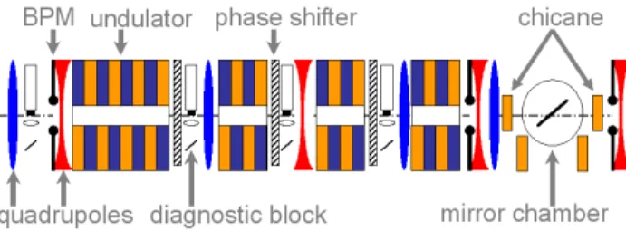
Figure 1: Schematic layout of the seeding experiment (not to scale), BC stands for bunch compressor stage.
length might not fit to the needs of ultrafast time resolved experiments. An alternative is to operate FLASH as an am- plifier of an injected seed from a high harmonic genera- tion (HHG) source. This approach gives several benefits compared to SASE. It makes possible to achieve higher shot-to-shot stability at GW-power level with a pulse du- ration given by the seed pulse of the order of 20 fs FWHM.
∗Work supported by BMBF contract No. 05 ES7GU1
†velizar.miltchev@desy.de