sFLASH: AN EXPERIMENT FOR SEEDING VUV RADIATION AT FLASH
A. Azima, J. B¨odewadt, H. Delsim-Hashemi, M. Drescher, S. Khan ∗ , T. Maltezopoulos, V. Miltchev, M. Mittenzwey, J. Roßbach, R. Tarkeshian, M. Wieland, University of Hamburg, Germany
S. D¨usterer, J. Feldhaus, T. Laarmann, H. Schlarb, DESY, Hamburg A. Meseck, BESSY, Berlin, Germany
Abstract
A seeded free-electron laser (FEL) experiment at VUV wavelengths, known as ”sFLASH”, is being prepared at the existing SASE FEL user facility FLASH. Beyond a proof-of-principle demonstration in the VUV, the empha- sis will be on high stability in terms of intensity and timing, thus providing an additional operation mode of FLASH for users. Seed pulses at wavelengths around 30 nm from high- harmonic generation (HHG) will interact with the electron beam in newly installed undulators upstream of the existing SASE undulator section. The seeded FEL radiation will be directed to a dedicated photon beamline for prototype pump-probe experiments.
INTRODUCTION
FLASH at DESY/Hamburg is a free-electron laser (FEL) based on the SASE principle, comprising a 1-GeV super- conducting electron linac and a 27 m long undulator, pro- ducing pulses of sub-10 fs duration down to 6.5 nm wave- length [1, 2]. Starting up from noise, the SASE radiation consists of a number of uncorrelated modes resulting in reduced longitudinal coherence and shot-to-shot intensity fluctuations of about 18 % rms [1]. One possibility to re- duce these fluctuations is to produce much longer radiation pulses with more modes contributing to the FEL output. A 3rd-harmonic rf system will be installed in 2009 to obtain 200 fs long electron bunches while retaining the present peak current [3]. An alternative approach is to operate the FEL as an amplifier of injected seed pulses from a high- harmonic generation (HHG) source. This way, not only a higher shot-to-shot stability at GW power, but a pulse du- ration of the order of 20 fs can be obtained. The natural synchronization between the FEL output and an external laser source will make pump-probe experiments insensi- tive to bunch jitter. Furthermore, the longitudinal coher- ence is expected to be greatly improved. An experiment recently performed at the SPring-8 Compact SASE Source [4] has demonstrated HHG seeding at 160 nm. At FLASH, an experiment (”sFLASH”) to study the feasibility of seed- ing at shorter wavelength (30 nm and below) is in prepara- tion, aiming at reliable user operation at a dedicated photon beamline, while SASE pulse trains are simultaneously de- livered to the present beamlines.
∗
contact: shaukat.khan@desy.de
LAYOUT Laser, HHG Source and Beamline
A laser laboratory adjacent to the FLASH tunnel, erected in 2007, will accommodate a Ti:sapphire system, produc- ing ultrashort (30 fs) pulses with a pulse energy up to 50 mJ at a rate of 10 Hz, matching the rate of bunch trains in FLASH. In order to facilitate access to the HHG source, it will also be situated in the laser lab in front of a tube leading to the FLASH tunnel as sketched in Fig. 1. After passing through a differentially pumped vacuum pipe, the HHG pulses are deflected upwards by ∼ 25
◦and focused by a curved mirror. Finally, the pulses are aligned with the electron beam by a 90
◦deflection using three flat mirrors, resulting in a better reflectivity than with a single mirror close to the Brewster angle. The mirrors are remotely con- trolled to steer the HHG beam in both planes. In addition, all mirrors are mounted on translation stages in order to switch between coatings designed for two different wave- lengths and – for the focusing mirror – different radii of curvature.
Undulators and Electron Beamline
The general layout of the experiment is shown in Fig. 2.
Four hybrid variable-gap undulators will be installed, one 4 m long device previously used in PETRA II with a pe- riod length of 33 mm [5] as well as three new 2 m long undulators designed for the PETRA III synchrotron light
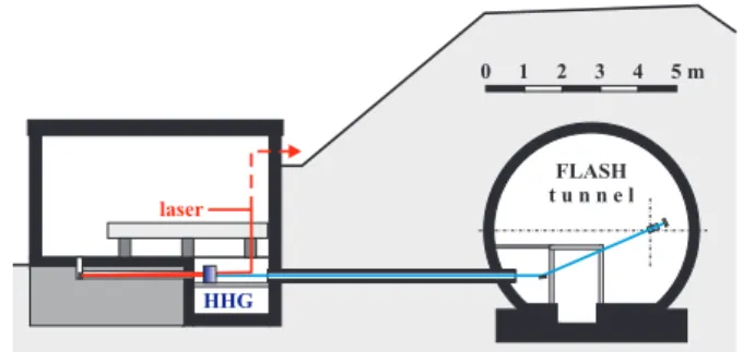
Figure 1: Cross section of the FLASH tunnel and the adja- cent laser laboratory. Under the laboratory floor, the HHG source and the incident laser beam (red) are aligned with a tube, through which the HHG pulses (blue) enter the tun- nel. A fraction of each laser pulse (dashed line) will be sent directly to the experiment for pump-probe applications.
Proceedings of FEL08, Gyeongju, Korea TUPPH072
Other
405
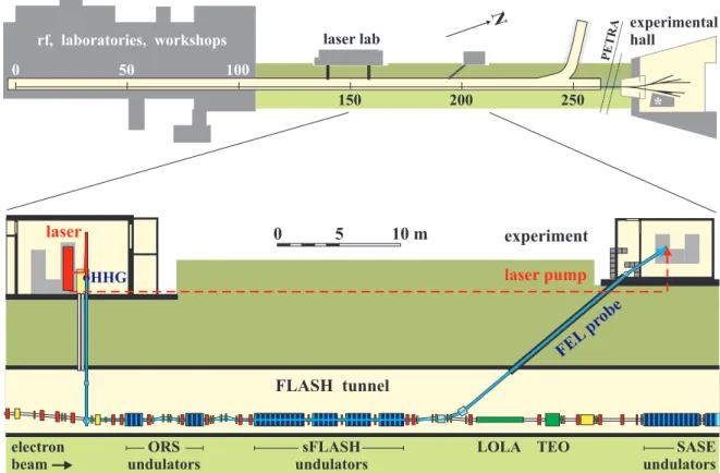
Figure 2: The FLASH facility (top) comprises a 260 m long tunnel housing the linac and undulators of a SASE FEL, followed by an experimental hall with photon beamlines. A 40 m long section (bottom) preceding the SASE undulators will be remodeled to accommodate four additional undulators for sFLASH. Seed pulses from high-harmonic generation (HHG) in a building adjacent to the FLASH tunnel will be aligned to the electron beam at a dog-leg chicane (left). At the undulator exit, the electron beam will be displaced while FEL radiation is sent by mirrors to an experimental hutch (see also Fig. 4). Delayed laser pulses will be sent directly to the hutch for pump-probe applications (dashed line). Also shown are dipole magnets and steerers (yellow), quadrupoles (red) and devices for longitudinal bunch diagnostics (ORS[7, 8], LOLA[9] and TEO[10]).
source with a period length of 31.4 mm [6]. Since there is only one dog-leg chicane allowing for backtangent entry of radiation pulses, the sFLASH undulator section will be pre- ceded by two already existing electromagnetic undulators used for the optical-replica synthesizer (ORS), in which the electron bunches interact with 800 nm laser pulses for diag- nostics purposes [7, 8]. The undulator section for sFLASH is shown in more detail in Fig. 3. Between the undulators,
Figure 3: Schematic layout of the sFLASH undulator sec- tion with diagnostics, phase shifters and quadrupole mag- nets between the undulators and a magnetic chicane further downstream to extract the FEL radiation by a mirror.
0.7 m long intersections accommodate a quadrupole mag- net, a phase shifter, and diagnostic devices such as beam position monitors. A phase shifter is a set of dipole mag- nets forming a small chicane in order to compensate the shift of the ponderomotive phase in the drift space between the undulators. At either end of the first undulator, a diag- nostics block is installed to determine and align the trans- verse position of electrons and HHG pulses. It comprises a wire scanner with a micro-channel plate to detect emit- ted or scattered photons, another screen to produce opti- cal transition radiation (OTR), and a Ce:YAG fluorescence screen. Within the undulators, extruded aluminum cham- bers with a vertical aperture of 9 mm and machined down to a wall thickness of 0.5 mm will be employed in order to maximize the range of wavelengths to which the undulators can be tuned. These chambers are similar to those designed for the European XFEL [11]. The quadrupole positions and the resulting beta functions in this region, shown in Fig. 5, were optimized using the code elegant [12] such that elec- trons passing the collimator of the upstream dog-leg section will not hit the chamber walls, thus protecting the undulator magnets against excessive radiation.
TUPPH072 Proceedings of FEL08, Gyeongju, Korea
Other
406
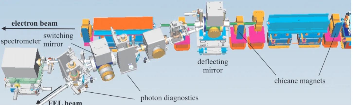
Figure 4: Extraction of the seeded-FEL radiation by a deflecting mirror pair while the electron beam (from right to left) is vertically displaced by a four-magnet chicane. The switching mirror pair directs the photon beam either to the spectrometer or to the experimental hutch outside the FLASH tunnel. The photon beam can be steered horizontally by the deflecting mirrors and in both planes by the switching mirrors by tilting the respective mirror chamber and observing the beam position at two diagnostics stations.
Photon Beamline and Experiment
At the exit of the undulator section, a magnetic chicane will displace the electron beam vertically, while the FEL pulses are extracted. Two pairs of plane amorphous carbon coated Si mirrors with grazing incidence at 5
◦will direct the pulses into a spectrometer
1located in the FLASH tun- nel, as shown in Fig. 4. The reflectivity of the mirrors at this angle is typically better than 85%. In the spectrom- eter, a 40 mm wide micro-channel plate with a CCD can be scanned along a Rowland circle, and data are read out by a fiber taper. Spectra can be recorded on a single-shot basis with a large dynamic range at wavelengths from 1 nm to 35 nm (at the detector center) with a resolution of λ/Δλ ≈ 1000. Alternatively to directing the FEL pulses into the spectrometer, they can be sent to an experimen- tal hutch outside the tunnel by switching the second mirror pair. Here, pump-probe experiments with a time resolution of the order of 30 fs can be performed by combining the seeded-FEL pulses with the naturally synchronized laser pulses.
CHALLENGES Mechanical Design and Installation
The mechanical design of mirror chambers, two for the HHG beamline, two for the FEL photon beamline is very demanding due to the many degrees of freedom, in which the mirrors have to be remotely controlled. Since windows are not permissible, differential pumping is required and great care must be taken to avoid any risk of contaminating the accelerator vacuum.
Squeezing the additional undulators together with mag- nets, diagnostics and experimental devices such as the ORS
1