Photon drag effect in (Bi
1−xSb
x)
2Te
3three-dimensional topological insulators
H. Plank,1L. E. Golub,2S. Bauer,1V. V. Bel’kov,2T. Herrmann,1P. Olbrich,1M. Eschbach,3L. Plucinski,3 C. M. Schneider,3J. Kampmeier,3M. Lanius,3G. Mussler,3D. Gr¨utzmacher,3and S. D. Ganichev1
1Terahertz Center, University of Regensburg, 93040 Regensburg, Germany
2Ioffe Institute, 194021 St. Petersburg, Russia
3Peter Gr¨unberg Institute (PGI) and J¨ulich Aachen Research Alliance (JARA-FIT), 52425 J¨ulich, Germany (Received 22 December 2015; published 29 March 2016)
We report on the observation of a terahertz radiation-induced photon drag effect in epitaxially grown n- andp-type (Bi1−xSbx)2Te3 three-dimensional topological insulators with different antimony concentrationsx varying from 0 to 1. We demonstrate that the excitation with polarized terahertz radiation results in a dc electric photocurrent. While at normal incidence a current arises due to the photogalvanic effect in the surface states, at oblique incidence it is outweighed by the trigonal photon drag effect. The developed microscopic model and theory show that the photon drag photocurrent can be generated in surface states. It arises due to the dynamical momentum alignment by time- and space-dependent radiation electric field and implies the radiation-induced asymmetric scattering in the electron momentum space. We show that the photon drag current may also be generated in the bulk. Both surface states and bulk photon drag currents behave identically upon variation of such macroscopic parameters as radiation polarization and photocurrent direction with respect to the radiation propagation. This fact complicates the assignment of the trigonal photon drag effect to a specific electronic system.
DOI:10.1103/PhysRevB.93.125434 I. INTRODUCTION
Much attention in condensed-matter physics is currently directed towards understanding electronic properties of Dirac fermions in three-dimensional (3D) topological insulators (TIs), which challenge fundamental concepts and hold great potential for electronic, optic, and optoelectronic applications (see, e.g., Refs. [1–9]).
Recently, nonlinear high-frequency electron transport phe- nomena [10–13] in TI systems have attracted growing interest.
There have been many theoretical and experimental works in the past few years on helicity-controlled photocurrents [14–18], the linear photogalvanic effect [19–21], local pho- tocurrents [22,23], edge photocurrents in two-dimensional (2D) TIs [24,25], coherent control of injection currents [26,27], photon drag currents [19,28,29], second-harmonic genera- tion [30], photoinduced quantum Hall insulators [31,32], cyclotron-resonance-assisted photocurrents [33,34], quantum oscillations of photocurrents [35], photogalvanic currents via proximity interactions with magnetic materials [36–38], and the photoelectromagnetic effect [39]. These phenomena, scaling in the second or third order of the radiation electric fields, open up new opportunities to study Dirac fermions, which has been already demonstrated for graphene (for a review see Ref. [13]) and several TI materials (see, e.g., Refs. [15,19,23,34]). An important advantage of the nonlinear high-frequency transport effects is that some of them, being forbidden by symmetry in the bulk of most 3D TIs, can be applied to selectively probe the surface states even in TI ma- terials with a finite bulk conductivity. Utilizing photocurrents, this advantage has been used to study Sb2Te3 and Bi2Te3
3D TIs [19], in which conventional dc transport experiments, particularly at room temperature, are handicapped by a large residual bulk charge-carrier density [40–45].
It has been shown in Ref. [19] that the photocurrent excited by normal incident terahertz (THz) radiation is generated
due to the photogalvanic effect. The latter originated from the asymmetric scattering of Dirac fermions driven back and forth by the ac electric field and is allowed only in the noncentrosymmetric surface states. The experiments further hinted at a possible contribution of the photon drag effect, a competing photocurrent resulting from the light momentum transfer to charged carriers. However, no experiments which provide clear evidence of the photon drag effect in TI materials have been reported so far.
Here we report on the observation of the photon drag effect in (Bi1−xSbx)2Te33D TIs excited by THz radiation. We demonstrate that while at normal incidence the photocurrent is dominated by the photogalvanic effect, at oblique incidence it is outweighed by the photon drag effect. The latter is shown to be caused by thein-planecomponent of the photon wave vectorq. Strikingly, the observed photon drag current does not change its sign upon invertingq. This seemingly surprising result is caused by the fact that in materials with trigonal symmetry the photon drag current is proportional not only to the photon wave vector but also to the product ofin-andout-of- planecomponents of the radiation electric field. Since bothq and the product of the electric fields change their sign, the total sign remains unchanged. Importantly, the trigonal photon drag effect can be generated in the surface states as well as in the bulk, being described by the same phenomenological equation.
Our experimental findings are well described by the developed theory and microscopic model based on the Boltzmann kinetic equation for the carrier distribution function. Both photon drag and photogalvanic effects are investigated in epitaxially grown (Bi1−xSbx)2Te3bulk materials of various compositions determined by the antimony content x. The variation of x enabled us to study photocurrents in different systems, including binary and ternary TIs with smooth changes fromn- top-type bulk conductivity (see Refs. [46,47]), as well as in heterostructure samples, consisting of ann-type Bi2Te3and a p-type Sb2Te3layer (see Ref. [48]). In the latter the chemical
TABLE I. Sample parameters and the amplitudes of photocurrentsAx excited by normal incident radiation withf =3.3 THz. Angles of incidenceθ=0 and 180◦correspond to the front and back excitation, respectively.
Sb content Type Bulk Ax (nA cm2/W)
Sample ID Type Structure x carriers θ=0 θ=180◦
BST127 binary 20 nm Bi2Te3 0 n 0.32 0.8
BST307 binary 13 nm Bi2Te3 0 n 3.1 7
BST323 ternary 24 nm (Bi1−xSbx)2Te3 25 n 1.8
BST306 ternary 23 nm (Bi1−xSbx)2Te3 40 n 0.06 0.04
BST641 ternary 175 nm (Bi1−xSbx)2Te3 43 n 0.4 0.6
BST305 binary 27 nm Sb2Te3 100 p 0.025 0.02
BST508 heterostructure 10 nmn-Bi2Te3 − − 0.3
+7.5 nmp-Sb2Te3
potential can be tuned by varying the thickness of the upper Sb2Te3layer.
II. SAMPLE DESCRIPTION
The samples were grown by molecular beam epitaxy (MBE) on Si(111) substrates in the so-called van der Waals (vdW) growth mode [49]; that is, there are only weak bonds between the substrate and the TI epilayers, so that the large lattice mismatch does not hinder the growth of single-crystal TI films with a high structural quality [50–52]. Before insertion into the MBE chamber, the Si(111) surface was chemically cleaned to remove the native SiO2 and to passivate the
surface with hydrogen. Prior to the TI layer deposition, the substrate was heated up to 600◦C for 20 min to desorb the hydrogen atoms. The Bi, Sb, and Te atoms were deposited on the substrate using effusions cells, working at temperatures of 530◦C (Bi), 450◦C (Sb), and 380◦C (Te), whereas the substrate temperature was 300◦C. The Bi2Te3(Sb2Te3) layer was deposited with a slow growth rate of 27 nm/h (9 nm/h).
The sample BST641 was grown at temperatureTBi=470◦C, TSb=417◦C, TTe=330◦C, Tsubstrate=300◦C and with a growth rate of 10 nm/h for 1050 min, which corresponds to a thickness of 175 nm. The structure composition and thickness of all investigated samples are given in the TableI. To characterize the samples, electrical measurements on Hall-bar
FIG. 1. ARPES investigation of the surface electronic structure of different TI samples, measured at low temperature (T ≈25 K) using photon energy of 8.4 eV. The spectra unambiguously prove the existence of topological surface states in each material. (a) Results for pure n-type Bi2Te3. The corresponding results for samples (b) BST306 and (c) BST641, i.e., then-type (Bi0.6Sb0.4)2Te3 and (Bi0.57Sb0.43)2Te3
ternary TIs, (d) for sample BST508, i.e., then-type 10-nm Bi2Te3/7.5-nm Sb2Te3 TI heterostructure, and (e) for sample BST305, i.e., the p-type Sb2Te3. The top panels depict the constant-energy contour atεB =0 with indicated crystallographic directions showing the hexagonal warping of the energy spectrum of the topological surface states. The middle panel illustrates the binding-energy-dispersion spectraε(k) map atky =0 along the ¯Mdirection, where the upper part of the topological surface states is revealed while the Dirac point is buried in the bulk valence-band maximum. Additionally, the energy distribution curves, integrated over the entire image, are shown beside the middle panels.
The bottom panels depict the respective momentum distribution curves. The ones forεB=0 are highlighted in red.
FIG. 2. (a) X-ray-diffraction pole figure scan around the (1,0,5) reflection of the Bi2Te3 sample BST127 showing that one domain orientation (highlighted by the solid red line) dominates. It also reveals that the crystallographic axes lie parallel to the sample edges.
Insets sketch domain orientations illustrated by the solid red line connecting the top Bi atoms in the top right panel and the side view of one quintuple layer (see the bottom right panel). (b) Photocurrent Jx(α)/I in Bi2Te3 sample BST127 measured for front and back illumination atT =296 K. Solid lines show fits after Eq. (1). Note that the same dependencies are obtained after phenomenological [see Eq. (4)] and microscopic theory [see Eq. (19)] for the photogalvanic effect.
structures using a standard four-point probe and lock-in technique were carried out at T =1.5 K. The bulk charge- carrier densities have been determined as follows: For binary n-type Bi2Te3 and p-type Sb2Te3 the bulk carrier density isn≈p≈5×1019 cm−3. For ternary (Bi1−xSbx)2Te3alloys withxof about 0.4–0.5 we obtainn≈p≈5×1018cm−3. The sample (Bi0.57Sb0.43)2Te3(BST641), the most insulating in the bulk, isntype and has a carrier density ofn=3×1017cm−3. The existence of topologically protected surface states has been verified by means of angle -resolved photoemission spectroscopy (ARPES) [53,54] (see Fig.1). Selected samples have been exposed to air and were transferred into a laboratory- based high-resolution ARPES chamber. In order to remove the oxidized layer and surface contaminants, the samples needed to be cleaned by repeated steps of gentle sputtering using 750 eV Ar ions and annealing to 250◦C to 280◦C.
After this cleaning procedure ARPES maps were obtained at low temperatures (T ≈25 K) employing a monochromatized microwave-driven Xe source with a photon energy of 8.4 eV.
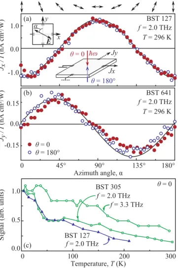
FIG. 3. (a) Photocurrent Jx/I measured in Bi2Te3 sample BST127. (b) PhotocurrentJy/Imeasured in (Bi0.57Sb0.43)2Te3sample BST641. Plots show the dependence of the photocurrent excited by normal incident radiation withf =2.0 THz on the azimuth angleα.
Angles of incidenceθ=0 and 180◦correspond to the front and back excitations, respectively. Solid lines show fits after Eq. (1). Note that the same dependencies are obtained after phenomenological [see Eq. (4)] and microscopic theory [see Eqs. (19) and (26) for the photogalvanic and the photon drag effect, respectively]. Insets sketch the setup and the orientation of the electric field. Note that the photocurrent is probed in the directions coinciding with the principal axes of the trigonal system. (c) Temperature dependence of the photocurrent measured in the Bi2Te3sample BST127 and Sb2Te3
sample BST305. All data are normalized to the value forT =4.2 K.
Topological surface states have been identified in all of the samples (see also Refs. [47,48]). Further, the energetic position of the Dirac point εB(DP) was extracted from the ARPES data. For all samplesεB(DP) are on the order of hundreds of meV, comparable with values reported previously for similar materials [46].
Additionally, x-ray diffraction (XRD) measurements were performed in order to verify the single crystallinity of the thin films and the orientation with respect to the Si(111) substrate and to determine the domain orientation (see Fig.2).
The XRD data demonstrate the formation of two trigonal domains, which are mirror symmetric to each other, and
TABLE II. Frequencies and corresponding wavelengths used in the experiments.
f(THz)
3.9 3.3 2.0 1.1 0.8 0.6
λ(μm) 77 90 148 280 385 496
show, however, that the majority of the domains have the same orientation [19,55]. The domains can also be seen in the atomic force microscopy images showing trigonal islands (not shown). Height profiles prove that the quintuple layers (QL) have steps of about 1 nm [19,51]. Using the XRD results, we prepared square-shaped samples with edges cut along crystallographic axesxandy(see Fig.2). To enable electrical measurements two pairs of Ohmic contacts were prepared in the middle of the 5×5 mm square sample’s edges.
III. EXPERIMENTAL TECHNIQUE
Experiments on photocurrents in (Bi1−xSbx)2Te3 3D TIs were performed while applying radiation from a high-power pulsed molecular THz laser [56,57]. Using NH3, D2O, and CH3F as active gases for the optically pumped laser, 40-ns pulses with a peak power of P ≈10 kW were obtained at different frequencies f (see Table II and Refs. [58–60]).
The radiation induces indirect (Drude-like) optical transitions
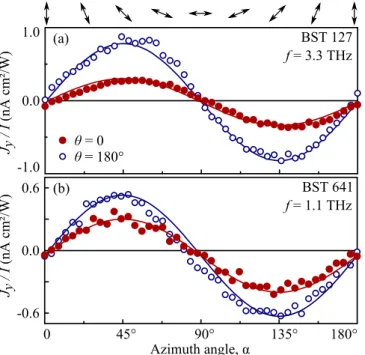
FIG. 4. (a) Jy/I measured in Bi2Te3 sample BST127 forf = 3.3 THz. (b)Jy/Imeasured in (Bi0.57Sb0.43)2Te3sample BST641 for f =1.1 THz. The data show the dependence of the photocurrent on the azimuth angleαexcited by normal incident radiation. Angles of incidenceθ=0 and 180◦correspond to the front and back excitations, respectively. Solid lines show fits after Eq. (1). Note that the same dependencies are obtained after phenomenological [see Eq. (4)] and microscopic theory [see Eqs. (19) and (25) for the photogalvanic and theqz-photon drag effects, respectively].
because the photon energies are much smaller than the carrier Fermi energy. The beam had an almost Gaussian form, which was measured by a pyroelectric camera [61,62]. A typical spot diameter depends on the radiation frequency and varies between 1 and 3 mm. The electric field amplitudeE0 of the incoming radiation was varied from about 1 to 30 kV/cm (radiation intensitiesIfrom about 1 to 1000 kW/cm2).
The samples were illuminated at normal and oblique incidence. In experiments at normal incidence front and back illumination was used with an angle of incidenceθ=0◦ and 180◦, respectively (see Figs. 3 and4). In the measurements applying oblique incident radiation the angleθ was varied between−35◦and 35◦(see insets in Figs.5and6). Note that larger angles of incidence were not used in order to avoid the illumination of contacts and edges. The photocurrents were analyzed in two directions, x and y, perpendicular to each other and parallel to the sample edges (see inset in Fig.3).
Most experiments at oblique incidence were carried out for the (yz) plane of incidence. In some additional measurements the orientation of the plane of incidence was rotated by the angleψ with respect to the (yz) plane (see inset in Figs. 7 and8).
The dc photocurrentJwas excited in the temperature range fromT =4.2 to 296 K. It was measured as a voltage drop, U∝J, across a 50load resistor and recorded in unbiased samples with a storage oscilloscope. To control the incidence power of the laser the signal was simultaneously measured at a reference THz detector [63]. To examine the photocurrent
FIG. 5. Azimuth angle dependencies of the photocurrentJy/I excited in (Bi0.57Sb0.43)2Te3sample BST641 by normal and oblique incident radiation. The data demonstrate that the polarization depen- dence does not change upon variation of the angle of incidence either for (a) the case in which the current decreases at oblique incidence (f =2.0 THz) or (b) the case in which it increases with increasing|θ|
(f =3.3 THz). Solid lines show fits after Eq. (1). Note that the same dependencies are obtained after phenomenological [see Eq. (4)] and microscopic theory [see Eqs. (17), (19), and (25) for the photogalvanic and both photon drag effects].
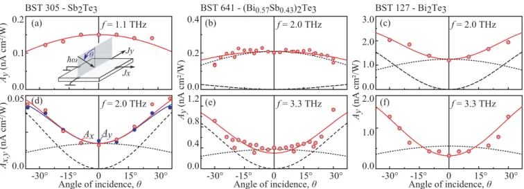
FIG. 6. Dependencies of the photocurrent amplitudesAx,yon the angle of incidenceθobtained for different frequencies and three samples:
Sb2Te3(BST305), (Bi0.57Sb0.43)2Te3(BST641), and Bi2Te3(BST127). Solid lines show fits after Eq. (4) and calculations after Eqs. (19), (25), and (17). Dotted and dashed lines show contributions of the photogalvanic effect and photon drag effect caused by theqx component of the photon wave vector. The curves are calculated after Eqs. (19) and (17), respectively. Note that solid curves in (e) and (f) are obtained by also taking into account the contribution of the photon drag effects caused by theqzcomponent of the photon wave vector. The latter effect (not shown) mainly contributes to the signal at normal incidence and is the cause of the difference between the value of the calculated total photocurrent (solid line) and the photogalvanic effect contribution (dotted line). It has a negative sign and decreases with increasingθ. The relative contributions of the photogalvanic and photon drag effects are obtained from the measurements applying front and back illuminations;
see Figs.3and4as well as TableI. The inset in (a) sketches the setup.
behavior upon the variation of the polarization state half- and quarter-wavelength plates were employed. The initial laser radiation was linearly polarized along the y axis. By using λ/2 plates, the azimuth angleαwas varied between the linear polarization of the sample and they axis (see inset and top panel in Fig.3).
By applying λ/4 plates, we obtained elliptically (and circularly) polarized radiation. In this case, the polarization state is determined by the angle ϕ between the plate optical axis and the incoming laser polarization. Here the electric field vector is lying parallel to thexaxis. The polarization states for
FIG. 7. Azimuth angle dependencies of the photocurrentJy/I excited in Bi2Te3sample BST127. The data are obtained at oblique incidence radiation (f =2.0 THz) forθ=20◦and different orienta- tions of the plane of incidence with respect to theydirection given by the angleψ; see the inset. The data are shown for the anglesψ=0◦, 40◦, and 90◦. The solid lines are calculated after Eq. (5).
severalϕare shown in the top panel of Fig.9. In this geometry, the radiation helicity is varied asPcirc=sin 2ϕ[64,65].
IV. EXPERIMENTAL RESULTS
Irradiating the (Bi1−xSbx)2Te3 3D TIs with linearly polar- ized THz radiation, we observed a dc current in both thex andy directions. The photocurrent was detected in the whole frequency range used from 0.6 up to 3.9 THz. The signal followed the temporal structure of the laser pulse. Its variation upon rotation of the polarization plane is well fitted by
Jx =[−A(f) cos 2α+C(f)]E02,
Jy =[A(f) sin 2α+C(f)]E02, (1) in whichE02∝I is the squared radiation electric field andA, C, andCare fitting parameters [see Figs.3(a)and3(b)]. The above polarization dependencies were observed in all samples and for all frequencies. Cooling the sample from room tem- perature to 4.2 K did increase the photocurrent amplitude [see Fig.3(c)], whereas the overall behavior remained unchanged.
As we have shown in Ref. [19], two phenomena can be the cause of the THz radiation-induced photocurrents, described by Eqs. (1), namely, the photogalvanic and the photon drag effects [66]. Experiments applying front and back illumination with normally incident radiation allow us to distinguish them from each other. While the photogalvanic current is determined by the in-plane orientation of the radiation electric field [19]
and, consequently, remains unchanged for both geometries, the photon drag current is additionally proportional to a component of the photon momentumq. Therefore, changing q→ −q (front to back illumination) does not affect the photogalvanic effect but inverts the sign of the factorA(f) for
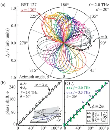
FIG. 8. (a) Azimuth angle dependencies of the photocurrent Jx/I excited in Bi2Te3 sample BST127. The data are obtained at oblique incidence radiation (f =2.0 THz) forθ=20◦and different orientations of the plane of incidence with respect to theydirection given by the angleψ. The data are shown for the angleψchanging from 0◦to 130◦with steps ofψ=10◦. Solid lines show fits after Eqs. (5). The measured phase shift as a function ofψfor (b) the data shown in (a) and (c) samples BST641, BST127, and BST305 and two radiation frequencies. Here solid and open symbols correspond to the frequenciesf =2.0 and 3.3 THz, respectively. The solid line shows a fit withφ=2ψ.
the photon drag effect. Note that for front and back illumination at normal incidence the wave vectorq is directed parallel or antiparallel to thezdirection. As an important result we found that the sign of the amplitudeA(f) remains unchanged (see exemplary Figs. 3 and4 for samples BST127 and BST641 and TableIfor all investigated samples atf =3.3 THz). This fact provides clear evidence that the photocurrent at normal incidence is dominated by the photogalvanic effect in the investigated 2D Dirac fermion systems. In samples BST127 and BST641 excited with f =2.0 THz, the contribution of the photon drag is vanishingly small (see Fig. 3). At other frequencies and samples the photon drag effect may yield a contribution up to one third compared to that of the photogalvanic effect, resulting in larger signals for back illumination than for the front one [67] (see Fig.4and TableI).
So far we have presented data obtained for normal incidence. Illuminating the samples at oblique incidence, we found that all characteristic properties of the photocur- rent, including its polarization behavior, remain unchanged (see Fig. 5). In contrast to the measurements at normal incidence, the magnitudeAx,y(f,θ) depends now additionally on the incident angleθ, as well as on the direction in which the
FIG. 9. Helicity dependence of the photocurrent,Jx/I, measured in Bi2Te3sample BST127 at normal as well as oblique incidence in the direction normal to the plane of incidence. The ellipses on top illustrate the polarization states for various anglesϕ. Solid lines show fits after Eqs. (4), where the polarization-dependent terms take, for this geometry, the formJx =Ax(f)(cos 4ϕ+1)/2.
current is examined: At largeθand for the plane of incidence coinciding, e.g., with theyzplane the photocurrent magnitudes measured in thex andy directions become slightly different.
For some excitation frequencies the photocurrent amplitude Ax,y(f,θ) did decrease upon the increase of the angle θ, exemplarily shown for the current measured in thexdirection in Figs.5(a),6(a), and6(b). Note that the change ofAx,y(f,θ) is even in the angleθ.
Strikingly, at other radiation frequencies we observed that for positive as well as for negativeθ the signal rises with an increase of the angle of incidence [see Figs.5(b)and6(c)–6(f)].
This behavior is observed for photocurrents measured in directions parallel as well as normal to the plane of incidence [see Fig.6(d)]. It is also detected for any orientation of the plane of incidence. Figure 7 shows the corresponding data for three positions of the incident plane determined by the angle ψ. The figure reveals that the signal varies as Jy = Ay(f,ψ) sin(2α−φ)E02 and the most pronounced change in the photocurrents’ polarization dependence is the appearance of a φ=2ψ phase shift. A detected small variation of Ay(f,ψ) as a function ofψcannot be discussed earnestly since precise adjustment ensuring that, for differentψ, technically obtained by rotating the sample, the laser spot remains on the same sample position is hard to realize. To support the conclusion that the rotation of the incident plane results in a 2ψ phase shift, we measured photocurrents depending on the linear polarization by changing the angleψ by steps of 10◦ in the range from 0◦ to 130◦. Figure 8(a)demonstrates the dependencies obtained for Bi2Te3 sample BST127. The corresponding dependency of the measured phase shiftφon the angleψis shown in Fig.8(b), and that for other samples and frequencies is shown in Fig.8(c). The figures demonstrate that in all casesφ≈2ψ.
Finally, we discuss the results obtained by applying ellip- tically (circularly) polarized radiation. These measurements were particularly motivated by the search for the circular pho- togalvanic [14,68,69] and circular photon drag effects [70,71], i.e., photocurrents changing their direction upon switching of the radiation helicity [10,11,13], recently observed for Bi2Te3
TI excited by near-infrared light [30]. Applying radiation at oblique incidence and measuring the photocurrent in the direction normal to the plane of incidence (yz), i.e., in the geometry for which circular photogalvanic [30,72,73] and circular photon drag effects [13,70] are expected, we detected a current which can be well fitted byJx =Ax(f)(cos 4ϕ+1)/2 (see Fig.9). Figure9clearly shows that for circularly polarized radiation (ϕ=45◦and 135◦) the signal vanishes. In fact, the term in brackets describes the degree of linear polarization in theλquarter-plate geometry. Therefore, the observed current is identical to the one excited by linearly polarized radiation, which was already discussed above. Examining different samples in the whole investigated THz frequency range, we observed the same result: No trace of a helicity-dependent photocurrent has been detected.
To summarize, experiments on different types of TI samples provide a self-consistent picture demonstrating that the pho- tocurrents (i) are caused by effects proportional to the second power of the radiation electric field and can be excited by both normal and oblique incident radiation, (ii) are excited by linearly polarized radiation, (iii) vary with the azimuth angleα asJ ∝A(f,θ,ψ) sin 2αwith a possible phase shift depending on the experimental geometry and crystallographic direction in which the photocurrent is measured (see Figs.7and8), (iv) have the same sign but may have distinct magnitudes of the factorA(f) for front and back normal incident illumination (see Figs.3and4), and (v) are described by an even function of the angle of incidence θ with the magnitude A(f,θ) for different radiation frequencies, increasing or decreasing with an increase ofθ(see Figs.5and6).
V. DISCUSSION
Now we discuss the origin of the observed photocurrents, which are induced by spatially homogeneous terahertz radia- tion and scale with the second power of the radiation electric field. We begin with the standard way to treat second-order effects without going into microscopic detail, which makes use of the symmetry arguments. This approach allows us to explore what kind of photocurrents are allowed in the considered system and to describe their variation upon a change of the macroscopic parameters, such as radiation intensity, polarization, and incident angle. With this, the response of the charge carriers ensemble to the external field can be characterized conveniently by the coordinate- and time-dependent electric current density j(r,t). It is expanded in a power series in the external alternating electric fieldE(r,t) in the form of a plane wave:
E(r,t)=E(ω,q)e−iωt+iq r +E∗(ω,q)eiωt−iq r, (2) where ω=2πf is the angular frequency andq is its wave vector. Limiting the consideration to the second-order effects, we obtain the photocurrent densityj ∝J in the form [12,56]
jλ=
μ,ν
χλμνEμEν∗+
δ,μ,ν
TλδμνqδEμEν∗+ c.c., (3) where the expansion coefficientsχλμνandTλμνδare third- and fourth-rank tensors, respectively, andEν∗=Eν∗(ω)=Eν(−ω) is the complex conjugate ofEν. The first term on the right-hand side of Eq. (3) represents photogalvanic effects, whereas
the second term describes the photon drag effect containing additionally the wave vector of the electromagnetic field. We emphasize that while the photogalvanic effect requires the absence of an inversion center and can be excited only in the surface states of the investigated TIs, a photon drag current can be generated in the centrosymmetric bulk as well. Moreover, in the case of the trigonal, the photon drag effect is described by the same phenomenological equations for bulk and surface states and therefore behaves identically upon variation of macroscopic parameters, such as radiation polarization.
Equation (3) can be simplified considering the point group C3v, which describes the symmetry of the surface states in (Bi1−xSbx)2Te3. To be specific we first obtain the photocur- rents excited in the crystallographic directionsx andy with the radiation plane of incidence (yz). Taking into account the fact that we detected only photocurrents excited by linearly polarized radiation that are even in the angle of incidenceθ, we can omit all contributions of photocurrents sensitive to the radiation helicity and those giving a response that is odd in the angleθ. Under these conditions we derive forj
jx =(χ+Tzqz)
Ex2−Ey2
−TqyEyEz
=joff−cos 2α E0212
(χ−Tzqcosθ)
ts2+tp2cos2θ +Tqtp2sin2θcosθ
,
jy = −2(χ+Tzqz)ExEy−TqyExEz
=sin 2α tstp[(χ−Tzqcosθ) cosθ+Tqsin2θ/2]E02. (4) Heretp andtsare the Fresnel transmission coefficients fors- andp-polarized light, andjoffis the polarization-independent offset, which is equal to zero forθ =0 (see the Appendix).
The constants χ, T, and Tz are coefficients describing the photogalvanic effect, the photon drag effect at oblique incidence, and the photon drag effect at normal incidence, respectively.
At normal incidence we obtain the photogalvanic effect and the photon drag effect, caused by the z component of the photon wave vector. They are given, respectively, by the terms proportional to factorsχandTz. Both effects have the same polarization dependence and vary with the azimuth angle αaccording tojx ∝(Ex2−Ey2)∝cos 2αandjy ∝2ExEy ∝ sin 2α, in agreement with the results of experiments [see Figs.3,4, and Eq. (1)]. Forχ T qz reversing the radiation propagation direction (θ =0⇒θ=180◦) does not affect the polarization dependence. It may, however, change the signal magnitude because χ+Tzqz is different for negative and positive qz, corresponding to front and back illumination.
Exactly this behavior has been observed in experiments showing that at some frequencies the photon drag due to thez component of the wave vector yields a minor contribution to the total photocurrent (see values of Jx at θ=0◦ and 180◦ in Table I and Fig. 4). At oblique incidence the Ex
andqz components are reduced, and the magnitudes of both photocurrents diminish equally for positive and negative angle θ[see Fig.5(a)and dotted lines in Fig.6].
According to Eqs. (4), at oblique incidence the photon drag effect, coupled with the in-plane wave vectorqy, can also contribute to the total photocurrent. Its dependence on
the azimuth angle α formally coincides with that of the contributions discussed so far,jx ∝EyEz∝cos 2αandjy∝ ExEz∝sin 2α. However, it obviously vanishes at normal incidence (qy=0) and, in contrast to the photogalvanic effect, increases with the rising angle of incidence (see dashed lines in Fig. 6). Moreover, the sign of the products (EyEzqy) and (ExEzqy) stays the same for positive and negative θ. A dominating contribution of this effect has been observed at large angles of incidence for all samples and for almost all frequencies. The most clear evidence for this conclusion is supported by measurements shown in Figs.5(b)and6(c)–6(f) demonstrate that the photocurrent rises with the increase of the angleθ.
Rotation of the incident plane by the angleψchanges the relative orientation of the electric field and crystallographic axes, modifying Eqs. (4). Taking into account that in all exper- iments described above Tqy(χ+Tzqz) and considering small anglesθ, which is relevant to the experimental data of Figs.5and6, we obtain
jx ≈ −cos (2α−2ψ)(χ−Tzq+Tqθ2/2)t2E02, jy ≈sin (2α−2ψ)(χ−Tzq+Tqθ2/2)t2E20. (5) Here t =tp=ts is the amplitude of the transmission coefficient for small θ, and the offset current is omitted.
Equations for an arbitrary angle of incidence are given in the Appendix. Equations (5) show that the rotation of the incident plane mainly results in a 2ψ phase shift for both photocurrentsjx andjy. This phase shift has been observed for all samples and frequencies (see Figs.7and8). While the above results were obtained while considering the point group C3v of the surface states, our analysis shows that the same behavior of the photon drag current upon variation of radiation polarization, rotation of the plane of incidence, direction of radiation propagation, etc., is found for the bulk point-group symmetryD3d. Therefore, in contrast to photogalvanics, this photocurrent can be attributed to surface states or the electron gas in the bulk only by a careful analysis of the influence of different microscopic parameters on the photocurrent behavior.
VI. MICROSCOPIC MODELS
In general, second-order high-frequency effects are caused by the redistribution of charge carriers in the momentum space induced by the illumination of the sample with radiation. The resulting nonequilibrium distribution can contain components which are oscillating in time and space, as well as steady-state and spatially homogeneous ones. Hence, the irradiation may cause both ac and dc flows in a medium. Their magnitudes are nonlinear functions of the field amplitude, and their components are sensitive to the radiation polarization. In the following section we present models visualizing the physics of nonlinear responses. For simplicity we assume positively charged carriers, i.e., holes for which the directions of the carrier flow and the corresponding electric current coincide.
A. Trigonal photogalvanic effect
The model and the microscopic theory of the photogalvanic effect have been discussed in detail in Ref. [19], demonstrating that the photocurrent stems from the asymmetric scattering of
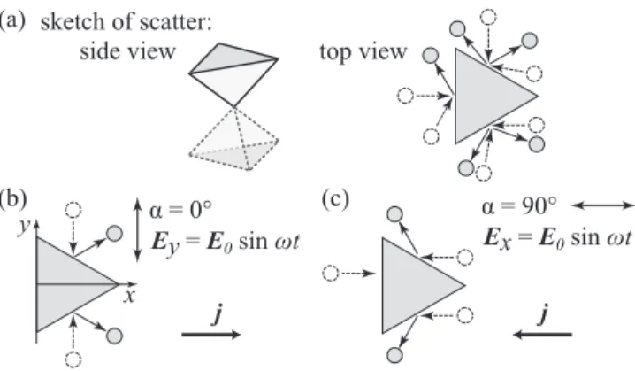
FIG. 10. Model of the photogalvanic effect, excited in surface states of (Bi1−xSbx)2Te3due to the asymmetry of elastic scattering of holes by wedges.
free carriers excited by irradiation with an ac electric field. As we show below, the asymmetric scattering is also responsible for the observed photon drag effects. Therefore, to introduce the concepts essential for the formation of the latter effects and to provide a complete picture of the photocurrent formation in TI, we will briefly address the model of the photogalvanic effect.
The current generation process is illustrated in Fig. 10.
As addressed above, the symmetry of the surface states in (Bi1−xSbx)2Te33D TIs isC3v. This point group implies that the anisotropy of carrier elastic scattering is the same as for scattering by a double triangular pyramid, whose side and top views are sketched in Fig.10(a). Note that forC3vsymmetry scattering by the top and bottom pyramids has different probabilities. In the framework of the photogalvanic effect caused by the in-plane motion of free carriers the scatterers can be considered randomly distributed but identically oriented wedges lying in the QL plane. The preferential orientation of wedges is supported by the x-ray data shown above [see Fig. 2(a) and Refs. [19,74]]. In the absence of radiation, the flows of anisotropically scattered holes [see right panel Fig. 10(a)] exactly compensate each other. Application of linearly polarized THz radiation results in an alignment of carrier momenta: the total flow of holes driven back and forth by ac electric field E(t) increases. The corresponding stationarycorrection to the hole distribution function scales as a square of the ac electric field magnitude [75]. Thestationary alignment of carrier momenta itself does not lead to a dc electric current, but due to asymmetric scattering by wedges, the excess of the flux of carriers moving along the field violates the balance of flows [73,76], and the linear photogalvanic current is generated [77]. The direction of the induced current depends on the relative orientation of the ac electric field and wedges: For example, a field parallel to the wedges’
base [Ey; see Fig.10(b)] yields the current flow in thex direction, while rotation of the electric field by 90◦reverses the current direction [see Fig.10(c)]. The polarization dependence of the photogalvanic current in the x and y directions is described by the terms withχ in Eqs. (5) and by Eq. (19).
Note that the coefficientχ has opposite signs for holes and electrons.
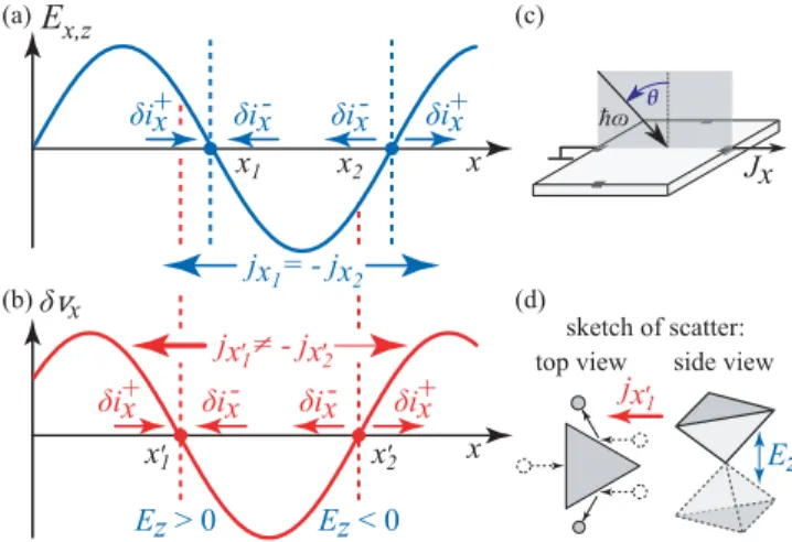
FIG. 11. Model of the trigonal photon drag effect caused by the in-plane wave vectorqx. To be specific, we discuss the hole gas in the surface states excited by oblique radiation with the incidence plane (xz); see (c). The triangle in the left picture in (d) shows the top view of the considered scattering potential. The side view of the scatters is sketched in the right picture.
B. Trigonal photon drag effects caused by the in-plane component of the photon wave vector
The trigonal photon drag effect caused by the in-plane component of the photon wave vector results in a dc current increasing with the increase of the angle of incidence. It is described by an even function of the angle θ. Similar to the photogalvanic effect, the photon drag current formation involves asymmetric scattering of free carriers and will be discussed in relation to the surface states. The model for the photon drag effect in the bulk is based on similar arguments but will not be further discussed here. The trigonal photon drag effect results from adynamicalalignment of carrier momenta.
It is generated due to the in-plane profile of the radiation electric field and implies the difference in the scattering probabilities for different half periods of the electromagnetic wave. The process of the current generation is illustrated in Fig. 11. Like in the model for the photogalvanic effect, we consider the scatterers to be randomly distributed but identically oriented pyramids in the QL plane [see Fig.11(d)].
In the absence of radiation, the flows of the thermalized charge carriers which are anisotropically scattered by pyramids exactly compensate each other. Optical excitation disturbs the balance due to the action of the high-frequency electric fieldE on charged carriers, we assume holes. The discussed trigonal photon drag current is caused by the dynamic variation of the electric field E in the direction of the radiation propagation [see Fig.11(a)]. The strength of the corresponding force acting on holes is given by|e|Eeiqr−iωt≈ |e|i(qr)Ee−iωt, where e is the elementary charge [13,78]. The force is coordinate dependent and causes the hole acceleration to be directed parallel to thexdirection forEx >0 (antiparallel forEx<0) and, consequently, to increase the hole flow by δi+x (δix−) [see horizontal arrows in Fig. 11(a)]. As a result of this dynamical momentum alignment the balance of the hole flows scattered by pyramids in the vicinity of the electric field Ex nodes becomes locally violated [see Figs. 11(a) and 11(d)]. The asymmetric scattering may cause equal in
magnitude but oppositely directed local electric currentsjx1 andjx2 in the vicinity ofx1andx2, whereas the total electric current remains zero. However, steady-state dc electric current indeed emerges if one additionally takes into account thez component of the radiation field and the retardation between the electric field and the instant velocity of the charge carrier.
The photocurrent reaches its maximum atωτabout unity. The effect of the retardation, well known in the Drude-Lorentz theory of high-frequency conductivity, causes a phase shift between the electric fieldExand the instant change of the hole velocityδvx given by arctan(ωτtr). Consequently, the nodes of the charge-carrier velocity δvx are shifted with respect to that of the electric fieldEx; these nodes are indicated in Fig.11(b)asx1 andx2. The carriers in the vicinity of thex1 andx2 positions are subjected to the electric fieldsEz(x1) and Ez(x2), which have opposite signs. TheEz(x1) [Ez(x2)] field is pushing the carriers to the base (top) of the pyramids, which increases (decreases) the scattering probability in the vicinity ofx1(x2). Consequently, it changes the magnitudes of the local currentsjx1 andjx2caused by the asymmetric scattering. The variation of the scattering probability upon the action of the out-of-plane electric fieldδWpp(Ez) is described by Eq. (11) in Sec.VII. As a result the oppositely directed local currents do not compensate each other anymore, and a dc electric current proportional to the productqxExEz emerges. Changing the angle of incidence fromθ to−θ reverses the sign of bothqx
and the productExEzso that the direction of the dc current remains unchanged. We emphasize that such a contribution to the photon drag effect is specific to trigonal systems and it is absent in, e.g., hexagonal systems like graphene [13,71].
VII. MICROSCOPIC THEORY
Now we turn to the microscopic theory of the photon drag effect, presented in the surface states. In the classical regime achievable in our experiments, which is characterized byωεF, the photocurrents can be well described by means of Boltzmann’s kinetic equation for the coordinate-dependent carrier distribution functionfp(r),
∂
∂t +eE(r,t)· ∂
∂p +vp· ∂
∂r
fp(r)
=
p
[Wp pfp(r)−Wppfp(r)], (6)
wheree >0 for holes and e <0 for electrons,vp=v0p/p is the velocity of surface charge carriers with a momentum p, v0 is the Dirac fermion velocity, andWpp is the probability of a charge carrier having momentapand pbefore and after scattering, respectively. The lack of an inversion center for the surface charge carriers makes their elastic scattering asymmet- ric, so thatWp p=W−p,−p[73,76], and a dc electric current results. Note that this asymmetry takes place even for isotropic scatterers like impurities or phonons. The photocurrent can be calculated as follows [12]:
j =e
p
vpδfp, (7)
where δfp is the correction to the distribution function quadratic in the radiation electric field amplitude and linear in the photon momentum.
To calculate the asymmetric part of the scattering prob- ability, which is responsible for the photocurrent formation, we take into account warping of the energy spectrum. Without warping, the energy dispersion of the surface states is described by the Hamiltonian [1]
H0=v0(σxpy−σypx), (8) where σx,y are Pauli matrices. The Hamiltonian (8) yields the linear energy dispersionεe,h= ±v0p and corresponding wave functionse,h(0) =[1,∓iexp(iϕp)]/√
2 for electrons and holes, whereϕp is the angle between the carrier momentum pand thexaxis. The warping of the energy spectrum reflects the trigonal symmetry of the surface and is described by, in addition to Eq. (8), a small term given by [79]
Hw=λwσzp3sin 3ϕp, (9) whereλwis a warping constant. This is the perturbation which leads to the hexagonal warping of the energy surfaces [80]
clearly detected by ARPES (see the top panels in Fig.1).
The perturbation caused by the terahertz radiation electric field Ez changes the surface charge-carrier wave functions due to the admixture of bulk states from various bands. The corresponding Hamiltonian is linear in the coordinatez,
Hem= −ezEz. (10) Taking into account both perturbationsHwandHemin the first order, we obtain the corrected electron wave function:
e=e(0)+λwp2sin 3ϕp
2v0
h(0)+eEz
n
zns
εn
n, where the index s labels the bulk orbitals from which the surface states are formed and n enumerates other energy bands of the bulk crystal. Here we assume that all bulk bands lie far enough away from the Dirac point so the energies
|εn| εF=v0pF, wherepFis the Fermi momentum.
Calculating the matrix elements of scattering by a static potential, we obtain from Fermi’s golden rule the scattering probability in the form Wpp=W(0)pp+δWpp. The field- independent part is given by the usual expression, taking into account the absence of back scattering for Dirac fermions [81]:
W(0)pp=π
|V(p−p)|2(1+cosθpp)δ(v0p−v0p), where V(p) is the Fourier image of the scattering potential, θpp=ϕp−ϕp is the scattering angle, and the angular brackets mean averaging over positions of scatterers [80]. The linear inEzcorrection is given by
δWpp= 2π
δ(v0p−v0p)
n
Im(VsnznsVss∗)/εn
×eEzsinθpp
λp2
v0 (sin 3ϕp+sin 3ϕp). (11) HereVssandVsnare the intra- and interband matrix elements of the scattering potential, respectively. The latter is caused by the short-range scatterers with the momentum transfer
∼/a0pF, wherea0 has an atomic scale; therefore, the average product is assumed to be independent of ϕp and ϕp[82]. We emphasize that the obtained correction, Eq. (11), is responsible for the effect of the Ez electric field on the scattering by pyramidlike scatters discussed in the model of the photon drag effect (see Sec.VI B).
Using the derived scattering probability Wpp, we solve the Boltzmann equation (6) and obtain the r-independent correction to the distribution functionδfp, which allows us to calculate the photon drag current given by Eq. (7). For this we will search for the correction to the distribution function responsible for the dynamical alignment momentum fp(da). First, we find the linear inEsolution given by
fp(E)(r)= −df0 dεp
eτtr
1−iωτtr(E·vp), (12) where f0 is the Fermi-Dirac distribution function and the transport relaxation time τtr determining the mobility of 2D Dirac fermions is related to the symmetric part of the scattering probability asτtr−1= pW(0)pp(1−cosθpp). The photon wave vector is accounted for by the space derivatives in the kinetic equation [13]
vp· ∂fp(E)
∂r =i(vp·q)fp(E) =
iω− 1 τ2
fp(da). (13) The timeτ2, which is of the order ofτtr, describes the relaxation of the above-discussed alignment of charge-carrier momenta.
It is defined as follows:
τ2−1=
p
W(0)pp(1−cos 2θpp). (14) From Eq. (13) we find the correction to the distribution function describing the dynamical alignment of momenta in the form
fp(da)= df0 dεp
ieτ2τtr(vp·q)(E·vp)−(q·E)v2p 2
(1−iωτtr)(1−iωτ2) . (15) Now we take into account the anisotropic scattering which manifests as a correction given by Eq. (11). Ther-independent correction to the distribution functionδfp is found from the following equation [83]:
p
δWpp
fp(da)+f(da)p
= −δfp
τtr . (16) Finally, from Eq. (7) we find the trigonal photon drag current. Experiments reveal that the photocurrent in all samples is caused by the linearly polarized radiation. For excitation by oblique incidence in the (xz) plane it is described by
jx =TqxExEz= eβλwpF2ωτ2(τtr+τ2) 4
1+ω2τ22 σ(ω)qxExEz, jy = −TqxEyEz. (17) Here the high-frequency conductivity is given by the Drude expression for degenerate 2D carriers,
σ(ω)= e2εFτtr 4π2
1+ω2τtr2.