Übersicht
• Zellgeometrie
• Frequency‐Reuse
• Übliche Systemfunktionen
• Ausbreitungsmodelle
• Traffic‐Engineering
• Beispiel GSM
• Beispiel UMTS
– 3G‐Systeme
– Diskussion von CDMA‐Systemen – Übersicht über das UMTS‐System – Power Control
– Handover Control
WS 2012/2013 Drahtlose Kommunikation ‐Zellulare Netze 68
Vor und Nachteile von CDMA
Vorteile
• Frequenzdiversität
• Mehrwegeresistenz
• Privacy
• Graceful‐Degradation Nachteile
• Self‐Jamming
• Nah‐Fern‐Problem
• Komplexeres Handoff
WS 2012/2013 Drahtlose Kommunikation ‐Zellulare Netze 69
CDMA: RAKE Receiver
WS 2012/2013 Drahtlose Kommunikation ‐Zellulare Netze 70
Bildquelle: William Stallings, „Wireless Communications & Networks“, Second Edition, Pearson Prentice Hall, 2005
CDMA: Hard‐ und Soft‐Handoff
• Handoff‐Verfahren in TDMA und FDMA immer dergestalt, dass ein Gerät an eine Basisstation angebunden ist.
• Vorig beschriebene Idee zu RAKE‐Reciever, lässt sich im CDMA‐Fall auch auf Handoff übertragen
• Wenn ein Mobilgerät mehrere Basisstationen gut empfangen kann
– Von Mobilgerät ausgesendete Signale werden von all diesen Basisstationen empfangen und an die Mobile‐
Switching‐Station weiter geleitet; Die Mobile‐Switching‐
Station kombiniert die Signale (z.B. Selection‐Combining) – Dasselbe geht auch in die umgekehrte Richtung. Alle
Basisstationen senden mit dem Code der Mobile‐Station.
Die Mobile‐Station kann die Signale ebenfalls kombinieren – (Vergleiche mit RAKE‐Receiver auf voriger Folie)
WS 2012/2013 Drahtlose Kommunikation ‐Zellulare Netze 71
Übersicht
• Zellgeometrie
• Frequency‐Reuse
• Übliche Systemfunktionen
• Ausbreitungsmodelle
• Traffic‐Engineering
• Beispiel GSM
• Beispiel UMTS
– 3G‐Systeme
– Diskussion von CDMA‐Systemen – Übersicht über das UMTS‐System – Power Control
– Handover Control
WS 2012/2013 Drahtlose Kommunikation ‐Zellulare Netze 72
WS 12/13 Drahtlose Kommunikation - Drahtlose Telekommunikationssysteme
UMTS Architektur
UTRAN
UE CN
Iu Uu
UTRAN (UTRA Network)
Mobilität auf Zellenebene
Radio Network Subsystem (RNS)
Kapselung der funkspezifischen Abläufe
UE (User Equipment)
CN (Core Network)
Handover zwischen Systemen
Location Management falls keine dedizierte Verbindung zwischen UE und UTRAN besteht
73
WS 12/13 Drahtlose Kommunikation - Drahtlose Telekommunikationssysteme USIM
Domain
Mobile Equipment
Domain
Access Network
Domain
Serving Network
Domain
Transit Network
Domain Home
Network Domain
Cu Uu Iu
User Equipment Domain
Zu
Yu
Core Network Domain Infrastructure Domain
UMTS Bereiche und Schnittstellen I
User Equipment Domain
Einem Benutzer zugeordnet, um auf UMTS Dienste zuzugreifen
Infrastructure Domain
Geteilt für alle Benutzer
Bietet den zugelassenen Benutzern UMTS Dienste an
74
WS 12/13 Drahtlose Kommunikation - Drahtlose Telekommunikationssysteme
UMTS Bereiche und Schnittstellen II
Universal Subscriber Identity Module (USIM)
Funktionen zur Verschlüsselung und eindeutigen Authentisierung des Benutzers
Auf der SIM untergebracht
Mobile Equipment Domain
Funktionen zur Funkübertragung
Teilnehmerschnittstelle zur Realisierung von Ende-zu-Ende- Verbindungen
Access Network Domain
Zugangsnetzabhängige Funktionen
Core Network Domain
Funktionen, die unabhängig vom Zugangsnetz sind
Serving Network Domain
Netz, das gegenwärtig den Zugang realisiert
Home Network Domain
Funktionen, die unabhängig vom aktuellen Aufenthaltsort des Benutzers dort zur Verfügung stehen
75
WS 12/13 Drahtlose Kommunikation - Drahtlose Telekommunikationssysteme
Zellatmung
GSM
Endgerät erhält volle Leistung der Basisstation
Anzahl eingebuchter Endgeräte hat keinen Einfluss auf die Zellgröße
UMTS
Zellgröße ist eng korreliert mit der Kapazität der Zelle
Kapazität ist bestimmt durch den Signal-Rausch-Abstand
Rauschen entsteht durch vorhandene Interferenz
anderer Zellen
anderer Teilnehmer
Interferenz erhöht das Rauschen
Endgeräte an der Zellgrenze können das Signal (aufgrund der Sendeleistungsbeschränkung) nicht weiter verstärken
keine Kommunikation möglich
Beschränkung der Teilnehmeranzahl notwendig
Zellatmung erschwert die Netzwerkplanung erheblich
76
WS 12/13 Drahtlose Kommunikation - Drahtlose Telekommunikationssysteme
Zellatmung: Beispiel
77
Übersicht
• Zellgeometrie
• Frequency‐Reuse
• Übliche Systemfunktionen
• Ausbreitungsmodelle
• Traffic‐Engineering
• Beispiel GSM
• Beispiel UMTS
– 3G‐Systeme
– Diskussion von CDMA‐Systemen – Übersicht über das UMTS‐System – Power Control
– Handover Control
WS 2012/2013 Drahtlose Kommunikation ‐Zellulare Netze 78
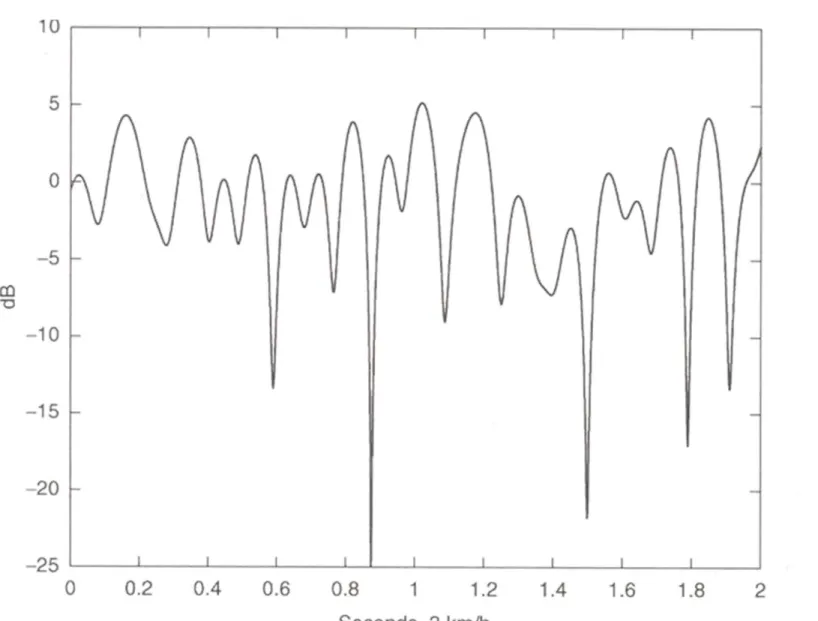
79 The near-far problem of CDMA
Large area may become blocked
Need to balance emitted power
Assume for now a target SIR for each UE
Goal: minimum TX power to keep the SIR
NodeB80 Fast fading spoils our plans
Figure copied from: Harri Holma and Antti Toskala, “WCDMA for UMTS”, 3rd Edition, WILEY, 2004, ISBN 0-470-87096-6
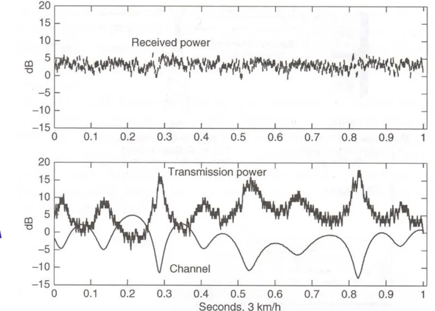
81 The solution: fast close loop power control
NodeB
execute in NodeB at rate 1.5kHz:
foreach UE i assigned to NodeB
estimate SIRest after rake combining if SIRest > SIRtarget then
generate TPC “DOWN” command for i if SIRest ≤ SIRtarget then
generate TPC “UP” command for i
82 Compensates a fading channel
Figure copied from: Harri Holma and Antti Toskala, “WCDMA for UMTS”, 3rd Edition, WILEY, 2004, ISBN 0-470-87096-6
83 Further remarks
And the downlink? basically the same…
A short reflection: closed loop power control
• Tight interaction between sender and receiver
• Useful for an interaction period
What if sender and receiver are not connected so far?
Example random access on RACH for
• Initial access
• Short packages
Open loop power control…
84 Open loop power control
Transmit power needs to be known to UE
Inaccurate! Fast fading between uplink and downlink is uncorrelated in WCDMA FDD
Does not consider interference at receiver
(Use power ramping to avoid excessive interference)
NodeB
• estimate path loss
• adapt power
• estimate path loss
• adapt power
85 How to choose the right target SIR?
Adjust target SIR to meet the link quality
Consider quality as BER or BLER
SIR for quality depends on
• Mobiles speed
• Multipath profile
Adjust SIR to the worst case?
• Unnecessary high SIR wastes capacity
• Desirable: minimal SIR which fulfils the quality requirement
How to find such SIR?
86
Finding the target SIR: outer loop power control
Similar method for the downlink
Downlink method resides in UE
Why is uplink handled in RNC?
Soft handover combining! …
NodeBexecute in RNC at rate of max 100Hz:
foreach UE i assigned to a NodeB
determine the quality from CRC attachment if quality better than required then
decrease SIRtarget = SIRtarget – ∆down else
increase SIRtarget = SIRtarget + ∆up
Radio Network Controller (RNC)
target SIR adjustment frame reliability
information
Übersicht
• Zellgeometrie
• Frequency‐Reuse
• Übliche Systemfunktionen
• Ausbreitungsmodelle
• Traffic‐Engineering
• Beispiel GSM
• Beispiel UMTS
– 3G‐Systeme
– Diskussion von CDMA‐Systemen – Übersicht über das UMTS‐System – Power Control
– Handover Control
WS 2012/2013 Drahtlose Kommunikation ‐Zellulare Netze 87
88 WCDMA Handover types
Inter-system (e.g. WCDMA and GSM)
Inter-frequency (needed at different cell layers or at hot spots)
Intra-frequency (what we look at here)
• Soft handover
• Softer handover
GSM GSM GSM GSM
WCDMA WCDMA WCDMA
GSM GSM
capacity extension coverage extension
Figures inspired from: Harri Holma and Antti Toskala, “WCDMA for UMTS”, 3rd Edition, WILEY, 2004, ISBN 0-470-87096-6
F1 F1 F1 F1
F2 F2
handover at hot spot
F1 F1 F1 F1
F2 F2 F2 F2 F2 F2 F2
handover to support macro and micro layers
89 The idea of soft handover
Exploiting multi path/antenna diversity (Macro diversity)
Uplink
• No additional signal is transmitted
• In principal, always increases performance
Downlink
• Each link causes interference at other users
• Trade-off
NodeB1
NodeB2
90 Soft handover: the downlink perspective
Maximal ratio combining (MRC) in the rake receiver
Recall: MRC used to exploit multi path diversity
Difference: rake receiver fingers use different codes
NodeB1
NodeB2
91 Soft handover: the uplink perspective
Selection combining (SC) in the RNC
Target SIR decided after SC
NodeB1NodeB2
NodeB1 NodeB2 SC
frame with CRC
frame with CRC RNC
92 Softer handover
Sectored antenna
Downlink: similar to soft handover
Uplink: the more effective MRC instead of SC is possible and used NodeB
93 Ingredients of the soft handover procedure
cell 1
cell 2
cell 3
CPICH Ec/I0 Measurement quantity, e.g.
CPICH Ec/I0
Active set: soft handover connection of UE
Neighbor/monitored set: set of cells that UE can measure
In the following example the active set size is 2
time
94 Adding a cell to the active set
cell 1
cell 2
cell 3
Event 1A (add cell2)
add add = reporting_range –
hysteresis_event1A
= window_add Active set is
not full Best
pilot
95 Replacing a cell in the active set
cell 1
cell 2
cell 3
Event 1A (add cell2)
Event 1C
(replace cell1 with cell3) Worst pilot in
full active set Best candidate pilot
replace
96 Removing a cell from the active set
cell 1
cell 2
cell 3
Event 1C
(replace cell1 with cell3)
Event 1B
(remove cell2)
Event 1A (add cell2)
remove
Best pilot
remove = reporting_range + hysteresis_event1B
= window_drop
Zusammenfassung und Literatur
• Zellgeometrie
• Frequency‐Reuse
• Übliche Systemfunktionen
• Ausbreitungsmodelle
• Traffic‐Engineering
• Beispiel GSM
• Beispiel UMTS
WS 2012/2013 Drahtlose Kommunikation ‐Zellulare Netze 97
Zusammenfassung
• Generelle Idee zellularer Netze: räumlich verteilte Basisstationen wegen beschränkter Bandbreite und limitierter Übertragungsreichweite
• Erfordert: Leistungskontrolle, Handover‐Mechanismen, aufwendige drahtgebundene Infrastruktur (drahtlos nur „auf der letzten Meile“)
• Bemerkung: das Thema schnurlose Telefone (z.B. DECT) wurde hier nicht betrachtet
• Vereinfachte Darstellung von Zellen mittels Hexagonen
• Zwei Varianten zur Aufteilung der Bandbreite: Zuweisung von Frequenzen, CDMA
• Alte Mobilefunkgenerationen: der Schwerpunkt ist hier die Sprachübertragung. (Eine Verbindung pro aktivem Nutzer)
• In der Mobiltelefonie spricht man von Evolution von alten Generationen hin zu neuen Generationen
• Neue Generationen: Datendienste werden immer wichtiger
– Evolution von leitungsvermittelnden zu paketorientiertem Netz (näher am Internet‐Modell)
• Beispiele: GSM und UMTS
WS 2012/2013 Drahtlose Kommunikation ‐Zellulare Netze 98
Literatur
[Schiller2003] Jochen Schiller, „Mobilkommunikation“, 2te überarbeitete Auflage, 2003
Kapitel 4.1.3: Luftschnittstelle Kapitel 4.1.8: Neue Datendienste Kapitel 4.4: UMTS
[Rappaport2002] Theodore Rappaport, „Wireless Communications, Principles and Practice“, Second Edition, Prentice Hall, 2002
10.1 Principles of Cellular Networks 10.3 Second‐Generation TDMA 10.4 Second‐Generation CDMA 10.5 Third‐Generation Systems
Weiterführende Literatur zum Thema UMTS (nicht unbedingt erforderlich zur Nachbearbeitung dieser Folien)
• H. Holma, A. Toskala (Ed.), “WCDMA for UMTS”, Wiley, 3rd edition, Wiley, 2004.
• R. Prasad, W. Mohr, W. Konhäuser (Ed.), “Third Generation Mobile Communications Systems”, Artech House, March 2000.
• J. P. Castro, “The UMTS Network and Radio Access Technology”, Wiley, 2001.
• 3GPP standards: TR 25.922: “Radio Resource Management Strategies”, 2007.
WS 2012/2013 Drahtlose Kommunikation ‐Zellulare Netze 99