Conference Paper
Non-linear spectrum-based analysis of rocking structures
Author(s):
Reggiani Manzo, Natalia; Vassiliou, Michalis F.
Publication Date:
2021
Permanent Link:
https://doi.org/10.3929/ethz-b-000476496
Originally published in:
http://doi.org/10.5592/CO/1CroCEE.2021.245
Rights / License:
In Copyright - Non-Commercial Use Permitted
This page was generated automatically upon download from the ETH Zurich Research Collection. For more information please consult the Terms of use.
ETH Library
NON-LINEAR SPECTRUM-BASED ANALYSIS OF ROCKING STRUCTURES
Natalia Reggiani Manzo(1), Michalis F. Vassiliou(2),
(1) PhD. Candidate, ETH Zürich, reggianimanzo@ibk.baug.ethz.ch
(2) Assistant Professor, ETH Zürich, vassiliou@ibk.baug.ethz.ch
Abstract
This paper proposes a simpler analytical system that can be used to describe the dynamics of Negative Stiffness Bilinear Elastic (NSBE) systems, and consequently design them in a simpler manner. The NSBE oscillator is a mathematical idealization, which can be used to describe rocking structures with or without flexible restraining systems or curved extension at their bases. The paper defines the characteristic quantities to make the bilinear system and actual rocking structures equivalent.
A simpler “equivalent” system to describe the behavior of NSBE systems is proposed. The equivalent system is the Zero Stiffness Bilinear Elastic (ZSBE) system, which is a bilinear system with zero stiffness in the second branch. The ZSBE system is useful and simpler because it needs one parameter less than the NSBE to be defined.
The paper proceeds by defining the “Equal Displacement” and “Equal Energy” rules that provide estimates of the maximum displacement of the NSBE based on the response of the ZSBE. Using a simpler system to predict the response of a more complicated one, is a concept similar to the RμT relations that provide estimates of the response of bilinear yielding systems based on the response of an equivalent linear elastic system. However the method should not be confused with the approach of FEMA 356: it does not resort to a linear elastic system but to the ZSBE.
Finally, the preliminary design of a real rocking structure is presented, as a case of study. The paper compares the response predicted by the proposed methodology to the one predicted by a more accurate numerical analysis.
Keywords: negative stiffness systems, dimensional analysis, non-linear dynamics, bilinear systems.
1. Introduction
Rocking has been proposed as a seismic isolation method for both bridges [1–20] and buildings [21–
23], because uplift works as a mechanical fuse and limits the design forces of both the superstructure and the foundation. Unlike structures designed to yield, the free rocking rigid block exhibits negative post-uplift stiffness [24]. In particular, this paper focuses on negative stiffness systems that are designed to sustain rocking motion without sliding [25-32], and do not exhibit hysteretic damping. Thus, it loads and unloads on the same branch. These systems do not accumulate displacements as negative stiffness hysteretic systems would. To avoid confusion, note that this paper uses the term “elastic” to describe not only linear elastic systems but also all systems that unload on the same branch, linear or nonlinear.
Therefore, an unrestrained rocking system is a negative stiffness elastic system.
Plastic design has found its way to practice, partially because a simplified design methodology, that is based on the linear elastic response spectrum, has been developed. For most structures designed to yield, a time history analysis is not required and an approach based on linear elastic spectra is allowed.
This convenient design approach was originally developed for elastoplastic systems, including the ones exhibiting post-yield hardening. It has been extended to include recentering (rocking) systems exhibiting positive post-uplift stiffness [33,34]. However, it is not applicable to negative stiffness rocking systems, because there is no “equivalent linear elastic system” for them [35]. Therefore, time- consuming time history analysis is required and the linear elastic response spectra that are defined by codes become useless for such structures.
This paper suggests that there can be a simplified design method for Negative Stiffness Bilinear Elastic (NSBE) systems (Fig.1a), based not on an equivalent linear elastic system, but on an equivalent
bilinear elastic system of constant restoring force (i.e., zero post-uplift stiffness)—a Zero Stiffness Bilinear Elastic (ZSBE) system (Fig.1b). Even though the equivalent ZSBE system does not present the convenience of a linear elastic system where the response scales proportionally to the excitation, it is useful because it reduces the dimensionality of the problem and it allows the development of design spectra (not linear elastic) for negative stiffness systems.
Figure 1. a) Characteristic pushover curve of the Negative Stiffness Bilinear Elastic (NSBE) system; b) Proposed bilinear elastic system of constant restoring force (Zero Stiffness Bilinear Elastic [ZSBE]) system.
It should be noted that the results of this study are not directly applicable to design procedures.
However, they suggest approaches that might be used to develop a rational design procedure for earthquake resistance of rocking structures.
2. Equivalent Description of Rocking Systems with NSBE Systems
One of the challenges in designing a rocking structure is that for a given height of a flat-based unrestrained rocking structure, usually defined by architectural considerations, its displacement capacity (i.e., the displacement that would cause overturn) is coupled to its uplifting force, because they both depend on its slenderness α (or, equivalently, on its base width 2b). Therefore, extending the base to increase the displacement capacity of the structure causes an increase in the design forces of both the superstructure and the foundation.
In an effort to isolate buildings via a rocking story, Soviet engineers [36] were the first to suggest a way to decouple the displacement capacity from the uplift acceleration: They extended the base of the block by a curved part. This increases the displacement capacity while keeping the uplifting acceleration constant [16]. The post-uplift stiffness can be positive or negative depending on the curvature of the extension. A similar behavior can be obtained by using a flexible restraining system [4,6].
The idealized systems presented above assume that the structure is rigid – a questionable assumption as the size of the blocks increase. Fig.1a shows the force-deformation curve of a rocking structure, when its deformability is considered [37-44]. In this case, the pre-uplift displacement is not zero but takes a finite value uup. Therefore, all systems cited above can be described by an elastic bilinear system, up to a linear approximation.
The SDOF NSBE studied here is shown in Fig.1a. It has a mass m and a restoring force described by Fig.1a. The initial positive stiffness (kpos) branch represents any pre-uplift deformability. The second branch has negative stiffness (kneg), and it starts at the uplift displacement (uup). The system displacement capacity (ucap) is defined as the displacement that results to zero restoring force, even though there are rare cases where a system can dynamically exceed this displacement without collapsing.
Based on its characteristic pushover curve, the oscillator’s equation of motion is:
( ) up ( ) g( ), ( ) up
up
m u t f u t m u t u t u
⋅ + ⋅ u = − ⋅ ≤ (1)
( ) up cap ( ) g( ), ( ) up
cap up
u u t
m u t f m u t u t u
u u
−
⋅ + ⋅ − = − ⋅ > (2)
The upper sign in Eq. 2 corresponds to a positive displacement and the lower to a negative displacement.
The main source of energy dissipation in rocking structures with protected ends is impact damping—unless extra damping is provided. For this reason, this paper assumes that the proposed NSBE model dissipates energy instantaneously. When the displacement is equal to the uplift displacement (i.e., when there is impact in the case of rocking structures), the integration is halted, and the post impact velocity is computed by a coefficient of restitution:
postimpact c
preimpact
r u
= u
(3)
Herein, the ratio of the preimpact to postimpact velocities will be assumed equal to 0.95. Notably, the system unloads on the same branch and does not dissipate energy while unloading (apart from the instantaneous energy loss when it reaches the yielding displacement).
For the case of rigid systems, the parameters of the system of Fig.1a that make it mathematically equivalent to a variety of rocking systems are given in [45].
3. Equal Displacement and Equal Energy Rule
Using the elastic spectrum for the analysis of negative stiffness structures would have been very convenient as engineers are used to it and as elastic spectra for design already exist and are included in codes. However, this is not feasible for NSBE systems, because their response has been proven to be uncorrelated to any “equivalent” elastic system [35].
Therefore, this section defines Equal Displacement and Equal Energy rules that are applied not on an equivalent elastic system but on an equivalent ZSBE system (Fig.1b). We refer to it as
“equivalent,” but this does not imply that it is linear elastic. It is a bilinear elastic system with finite pre-uplift displacement and zero post-uplift stiffness system.
To correlate the responses of the NSBE and of the ZSBE, the quantity of interest is the ratio:
, , dem NS dem ZS
u
γ =u (4)
where udem NS, and udem ZS, are the maximum displacements of the NSBE and ZSBE systems, respectively.
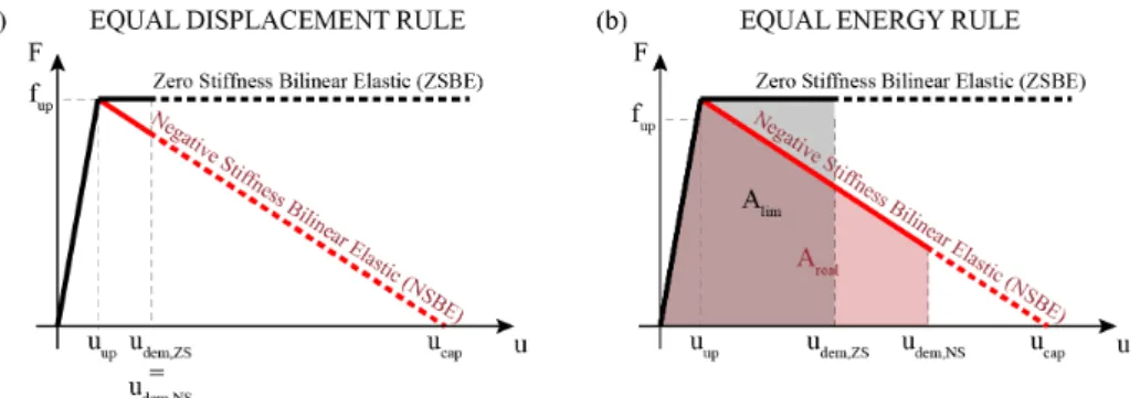
The Equal Displacement rule assumes that the NSBE and the equivalent ZSBE system will experience the same maximum displacement (Fig.2a):
, , 1
dem NS dem ZS ED
u =u →γ = (5)
The Equal Energy rule assumes that the monotonic loading curves of the NSBE and the ZSBE system will produce the same work, that is, the two shaded areas in Fig.2b are equal. Based on Fig.2b, one can compute that the Equal Energy rule gives:
Figure 2. a) Equal Displacement, and b) Equal Energy rules for NSBE systems
( ) (
,)
,
, , , ,
cap up cap 2 dem ZS up
dem NS cap EE
dem ZS dem ZS dem ZS dem ZS
u u u u u
u u
u u u u
γ = = − − ⋅ − ⋅ + (6)
4. Response of Rigid-Negative Stiffness Systems to Recorded Ground Motions
This section explores the accuracy of the rules defined in the section above, when applied to NSBE systems that present minimal pre-uplift displacement, i.e. systems with small uup.
4.1 FEMA P695 Ground Motions
There is no consensus in the engineering community on what ground motions should be used in time history analysis. This paper focuses on the near-field pulse like set of ground motions proposed by FEMA P695 [46], as pulse like ground motions are particularly destructive for rocking systems.
4.2 Median displacement spectra
Seismic design does not involve a single excitation, but a set of excitations that characterize the seismic hazard at a given site. Thus, this paper compares NSBE and ZSBE not by comparing their responses to individual ground motions, but by comparing the statistics of the responses to ensembles of ground motions [47]. The Equal Displacement and Equal Energy rules are assessed by focusing on the median displacement spectra for three variations of the set: scaled so that their PGV is equal to 0.5 PGV, or 1.0 PGV, or 2.0 PGV. PGV is defined as:
( )
PGV median PGV PGV1 ix iy i= N
= ⋅
(7)
where N is the number of ground motions and x and y are their two components.
4.3 Equal Displacement rule for NSBE systems
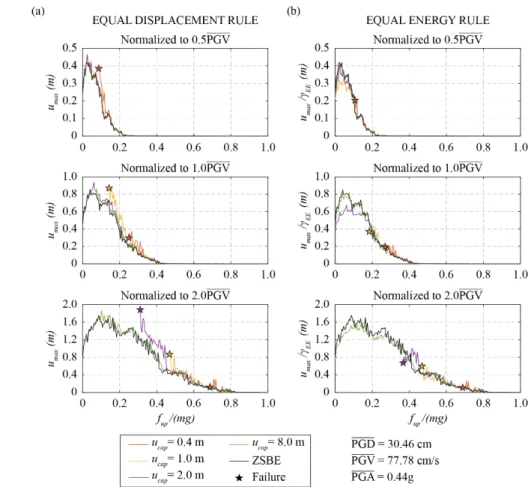
Fig.3a plots the median of the maximum displacement of the NSBE stiffness system as a function of its strength normalized by the system’s self-weight (fup /mg) for several values of the displacement capacity. The uplift displacement is set to uup=5×10⁻⁴ m to study quasi-rigid systems. For reasons of plot clarity, each line is plotted only for fup/mg> (fup/mg)crit, where (fup/mg)crit is the maximum uplift strength for which there is failure. The figure shows that:
a) As long as the system is not close to failure, the displacement only loosely depends on the displacement capacity. So, when the system is not close to failure, instead of computing a different spectrum for each displacement capacity, one can compute the spectrum for the ZSBE system (i.e. for an NSBE with ucap → ∞) and use it to calculate the displacement demand on any NSBE of the same strength.
b) As the system gets closer to collapse, the “Equal Displacement rule” does not apply and is unconservative: Systems with smaller displacement capacity exhibit larger displacements than the ones with larger displacement capacity. Moreover, close to failure the slope of the spectrum increases dramatically, i.e. a small decrease of the system strength would lead to a tremendous increase of the maximum displacement. This is not in agreement with a rational design, in which it would be required that this steep part is avoided.
4.4 Equal Energy rule for NSBE systems
Fig.3a show that the Equal Displacement rule is on the unconservative side, especially as the displacement demand approaches the capacity. To examine the performance of the Equal Energy rule, Fig.3b presents the median of the maximum displacement umax divided by the factor γEE (Eq.6) as a function of the system normalized strength fup/mg. The plots are constructed for several values of displacement capacity ucap and for uplift displacement uup=5×10⁻⁴ m.
Figure 3. a) Median displacement spectra; b) Median displacement spectra normalized by γEE
The curves almost collapse to a unique curve, the one that represents the ZSBE system. Notably, this happens for all 3 different scalings of the ground motions. Hence, the Equal Energy rule gives a good estimate of the maximum displacement of NSBE systems with a finite displacement capacity.
Comparing the Equal Displacement to the Equal Energy rule, the former is simpler, but the latter is overall more conservative, especially for larger displacements. Therefore, unless there is a reason to opt for simplicity, the use of the Equal Energy rule is proposed.
The above conclusions also hold for the near field non-pulse like and far field FEMA ground motion sets [45].
4.5 Design Example
Next, a case study is used to illustrate a design method based on the Equal Displacement and Equal Energy rules. The method is applied for the design of a rocking bridge equipped with a restraining system that increases the displacement capacity, while keeping the post-uplift stiffness negative.
The geometry of the bridge is typical of overpass bridges. The columns have a height of 9.6 m and a diameter of 1.6 m, whereas the deck is much heavier than the columns (γm→ ∞). Planar rocking (i.e., one directional excitation) is assumed as a first approximation (even though this has been proven unconservative [10,11]). Then, the proposed design steps are:
1. Calculate the normalized yielding strength of the system (fup/(mg)). If the restraining tendon is not prestressed, this depends solely on the column geometry, and is equal to α.
2. Obtain the displacement demand for the infinite capacity curve (udem,ZS) using the ZSBE curves. The ZSBE curves are the median response of the system subjected to ensembles of ground motions.
3. Calculate the design displacement capacity of the system, as:
, ,
cap dem NS dem ZS
u =FS u⋅ =FS⋅ ⋅γ u (8)
in which FS is a safety factor and γ is defined by Eq. 8. Two alternative approaches were evaluated:
One based on the Equal Displacement (γ = 1) and one on the Equal Energy (γ = γEE, Eq.6) rule.
Table 1 presents the design values when the two rules are applied on the set of ground motions under the three different scalings. ucap is the capacity required for a FS =2.5 (Eq.8). For a system with a displacement capacity ucap, udem,TH is the median displacement demand of each set computed with time history analysis. udem,EE and udem,ED are equal to γED·udem,ZS and γEE·udem,ZS, respectively. udem,ZS is the median response of the ZSBE system. The error is defined as error = (udem,ED/EE − udem,TH)/udem,TH.
Table 1. Design Values for the Equal Displacement (γ=1) and Equal Energy rule (γ = γEE)
Equal Displacement Equal Energy
.
0 5 PGV 1 0 PGV. 2 0 PGV. 0 5 PGV. 1 0 PGV. 2 0 PGV.
ucap (m) 1.60 1.60 3.65 1.60 1.85 4.56
udem,TH (m) 0.056 0.603 1.621 0.056 0.575 1.669
udem,ED (m) 0.051 0.592 1.459 0.051 0.740 1.823
Error (%) -10.08 -1.80 -10.01 -8.61 28.60 9.27
The Equal Displacement rule, in general, underpredicts the result, with a maximum underprediction error of 10%. The Equal Energy rule is conservative in 2 out of 3 cases. None of the rules led to collapse, because of the safety factor FS = 2.5.
5. Conclusions
Rocking systems (free, restrained, or with curved extensions) that exhibit negative post-uplift stiffness can be described as elastic bilinear oscillators with a negative stiffness second branch, herein denoted as NSBE. This description can also take into account their pre-uplift deformability.
In this paper, it was proposed that these systems can be described by an equivalent bilinear elastic system that has the same strength, zero post-uplift stiffness, and zero uplift displacement, i.e. a one- parameter system, a ZSBE system with zero uplift displacement. Based on this equivalent system, the response of the original negative stiffness oscillator can be obtained by either an “Equal Displacement rule” or an “Equal Energy rule”, the former being simpler, the latter being more accurate. The above methodology is similar to the “RμT” concept for elastoplastic structures with one fundamental difference: The equivalent system is not linear elastic, but a bilinear elastic system with zero stiffness of the second branch (ZSBE).
This equivalence suggests that the ZSBE oscillator should be extensively studied under a larger database of recorded ground motions to derive non-linear spectra describing its behavior. This will provide the engineering community with a tool to easily design rocking (or any other negative stiffness bilinear elastic) structures, without having to perform time consuming time history analysis.
6. Acknowledgment
This work was supported by the ETH Zurich under grant ETH-10 18-1.
6. References
[1] Makris, N., Vassiliou, M.F. (2013): Planar rocking response and stability analysis of an array of free standing columns capped with a freely supported rigid beam. Earthq. Eng. Struct. Dyn., 42 (3), 431-449.
[2] Sideris, P., Aref, A. J., & Filiatrault, A. (2014). Quasi-static cyclic testing of a large-scale hybrid sliding- rocking segmental column with slip-dominant joints. Journal of Bridge Engineering, 19(10), 04014036.
[3] Makris, N., Vassiliou, M.F. (2014): Are Some Top-Heavy Structures More Stable?. J. Struct. Eng., 140 (5).
[4] Makris, N., Vassiliou, M.F. (2014): Dynamics of the rocking frame with vertical restrainers. J. Struct. Eng., 141 (10), 04014245.
[5] Dimitrakopoulos, E.G., Giouvanidis, A.I. (2015): Seismic Response Analysis of the Planar Rocking Frame.
J. Eng. Mech., 141 (7), 04015003.
[6] Vassiliou, M.F., Makris, N. (2015): Dynamics of the Vertically Restrained Rocking Column. J. Eng. Mech., 141 (12), 04015049.
[7] Agalianos, A., Psychari, A., Vassiliou, M. F., Stojadinovic, B., & Anastasopoulos, I. (2017). Comparative assessment of two rocking isolation techniques for a motorway overpass bridge. Frontiers in built environment, 3, 47.
[8] Giouvanidis, A.I., Dimitrakopoulos, E.G. (2017): Seismic performance of rocking frames with flag-shaped hysteretic behavior. J. Eng. Mech., 143 (5), 04017008.
[9] Vassiliou, M.F., Mackie, K.R., Stojadinović, B. (2017): A finite element model for seismic response analysis of deformable rocking frames. Earthq. Eng. Struct. Dyn., 46, 447–466.
[10] Vassiliou, M.F., Burger, S., Egger, M., Bachmann, J.A., Broccardo, M., Stojadinovic, B. (2017): The three‐
dimensional behavior of inverted pendulum cylindrical structures during earthquakes. Earthq. Eng. Struct.
Dyn., 46 (14), 2261-2280.
[11] Vassiliou, M.F. (2018): Seismic response of a wobbling 3D frame. Earthq. Eng. Struct. Dyn., 47 (5), 1212- 1228.
[12] Bachmann, J.A., Strand, M., Vassiliou, M.F., Broccardo, M., Stojadinovic, B. (2018): Is rocking motion predictable?. Earthq. Eng. Struct. Dyn., 47 (2), 535-552.
[13] Dar, A., Konstantinidis, D., El‐Dakhakhni, W. (2018): Seismic response of rocking frames with top support eccentricity. Earthq. Eng. Struct. Dyn., 47 (12), 2496-2518.
[14] Kashani, M. M., Gonzalez-Buelga, A., Thayalan, R. P., Thomas, A. R., & Alexander, N. A. (2018).
Experimental investigation of a novel class of self-centring spinal rocking column. Journal of Sound and Vibration, 437, 308-324.
[15] Xie, Y., Zhang, J., DesRoches, R., & Padgett, J. E. (2019). Seismic fragilities of single‐column highway bridges with rocking column‐footing. Earthquake Engineering & Structural Dynamics, 48(7), 843-864.
[16] Bachmann, J.A., Vassiliou, M.F., Stojadinovic, B. (2019): Rolling and rocking of rigid uplifting structures. Earthq. Eng. Struct. Dyn., 48 (14), 1556-1574.
[17] Thiers‐Moggia R, Málaga‐Chuquitaype C (2019): Seismic protection of rocking structures with inerters. Earthquake Eng. Struct. Dyn., 48 (5), 528-547.
[18] Giouvanidis, A.I., Dong, Y. (2020): Seismic loss and resilience assessment of single-column rocking bridges. Bull. Earthq. Eng., 18, 4481-4513.
[19] Sieber, M., Klar, S., Vassiliou, M. F., & Anastasopoulos, I. (2020). Robustness of simplified analysis methods for rocking structures on compliant soil Earthq. Eng. Struct. Dyn, 49(14), 1388-1405.
[20] Thomaidis IM, Kappos AJ, Camara, A (2020): Dynamics and seismic performance of rocking bridges accounting for the abutment‐backfill contribution. Earthquake Eng. Struct. Dyn.. DOI: 10.1002/eqe.3283 [21] Bachmann, J.A., Vassiliou, M.F., Stojadinović, B. (2018): Dynamics of rocking podium structures. Earthq.
Eng. Struct. Dyn., 46 (14), 2499-2517.
[22] Aghagholizadeh, M., Makris, N. (2018): Earthquake response analysis of yielding structures coupled with vertically restrained rocking walls. Earthq. Eng. Struct. Dyn., 47 (15), 2965-2984.
[23] Ríos-García, G., Benavent-Climent, A. (2020): New rocking column with control of negative stiffness displacement range and its application to RC frames. Engineering Structures, 206, 110133.
[24] Housner, G.W. (1963): The behavior of inverted pendulum structures during earthquakes. Bull. Seimol. Soc.
Am., 53 (2), 404-417.
[25] Dar, A., Konstantinidis, D., El-Dakhakhni, W.W. (2016): Evaluation of ASCE 43-05 seismic design criteria for rocking objects in nuclear facilities. J. Struct. Eng., 142 (11), 04016110.
[26] Kalliontzis, D., Sritharan, S., Schultz, A. (2016): Improved coefficient of restitution estimation for free rocking members. J. Struct. Eng., 142 (12), 06016002.
[27] Chatzis, M. N., Espinosa, M. G., & Smyth, A. W. (2017). Examining the energy loss in the inverted pendulum model for rocking bodies. Journal of Engineering Mechanics, 143(5), 04017013.
[28] Sextos, A.G., Manolis, G.D., Ioannidis, N., Athanasiou, A. (2017): Seismically induced uplift effects on nuclear power plants. Part 2: Demand on internal equipment. Nucl. Eng. Des., 318, 288-296.
[29] Giouvanidis, A. I., & Dimitrakopoulos, E. G. (2017). Nonsmooth dynamic analysis of sticking impacts in rocking structures. Bull. Earthq. Eng., 15 (5), 2273-2304.
[30] Voyagaki, E., Kloukinas, P., Dietz, M., Dihoru, L., Horseman, T., Oddbjornsson, O., Steer, A. (2018):
Earthquake response of a multiblock nuclear reactor graphite core: Experimental model vs simulations.
Earthq. Eng. Struct. Dyn., 47 (13), 2601-2626.
[31] Di Sarno, L., Magliulo, G., D'Angela, D., Cosenza, E. (2019): Experimental assessment of the seismic performance of hospital cabinets using shake table testing. Earthq. Eng. Struct. Dyn., 48 (1), 103-123.
[32] Bao Y, Konstantinidis D (2020): Dynamics of a sliding‐rocking block considering impact with an adjacent wall. Earthquake Eng. Struct. Dyn., 49 (5), 498-523.
[33] Christopoulos, C., Filiatrault, A., Folz, B. (2002): Seismic response of self‐centring hysteretic SDOF systems. Earthq. Eng. Struct. Dyn., 31 (5), 1131-1150.
[34] Palermo A, Pampanin S, Calvi GM (2005): Concept and development of hybrid solutions for seismic resistant bridge systems. Journal of Earthquake Engineering, 9 (6), 899-921.
[35] Makris, N., Konstantinidis, D. (2003): The rocking spectrum and the limitations of practical design methodologies. Earthq.Eng. Struct. Dyn., 32 (2), 265-289.
[36] Polyakov, S.V. (1974): Design of Earthquake Resistant Structures. English tr. Moscow: MIR Publishers.
[37] Chopra, A.K., Yim, SCS (1985): Simplified earthquake analysis of structures with foundation uplift. J. Struct.
Eng., 111 (4), 906-930.
[38] Psycharis, I.N. (1991): Effect of base uplift on dynamic response of SDOF structures. J. Struct. Eng., 117 (3), 733-754.
[39] Anastasopoulos, I., Kourkoulis, R., Gelagoti, F., Papadopoulos, E. (2012): Rocking response of SDOF systems on shallow improved sand: An experimental study. Soil Dyn. Earthq. Eng., 40, 15-33.
[40] Acikgoz, S., DeJong, M.J. (2012): The interaction of elasticity and rocking in flexible structures allowed to uplift. Earthq. Eng. Struct. Dyn., 41 (15), 2177-2194.
[41] Vassiliou, M.F., Mackie, K.R., Stojadinović, B. (2014): Dynamic response analysis of solitary flexible rocking bodies: modeling and behavior under pulse‐like ground excitation. Earthq. Eng. Struct. Dyn., 43 (10), 1463-1481.
[42] Vassiliou, MF., Truniger, R, Stojadinović, B. (2015): An analytical model of a deformable cantilever structure rocking on a rigid surface: development and verification. Earthq. Eng. Struct. Dyn., 44(15), 2775-2794.
[43] Truniger, R., Vassiliou, M.F., Stojadinović, B. (2015): An analytical model of a deformable cantilever structure rocking on a rigid surface: experimental validation. Earthq. Eng. Struct. Dyn., 44 (15), 2795-2815.
[44] Avgenakis, E., Psycharis, I.N. (2020): Modeling of inelastic rocking bodies under cyclic loading. J. Eng.
Mech., 146 (4), 04020020.
[45] Reggiani Manzo, N., Vassiliou, M. (2021): Simplified Analysis of Bilinear Elastic Systems Exhibiting Negative Stiffness Behavior. Earthq. Eng. Struct. Dyn., 50 (2), 580-600.
[46] FEMA P695 (2009): Quantification of Building Seismic Performance Factors. Federal Emergency Management Agency, Rep. FEMA P695, Washington, D.47C.
[47] Vassiliou, M. F., Broccardo, M., Cengiz, C., Dietz, M., Dihoru, L., Gunay, S., ..., Stojadinovic, B. (2020).
Shake table testing of a rocking podium: Results of a blind prediction contest. Earthq. Eng. Struct. Dyn
![Figure 1. a) Characteristic pushover curve of the Negative Stiffness Bilinear Elastic (NSBE) system; b) Proposed bilinear elastic system of constant restoring force (Zero Stiffness Bilinear Elastic [ZSBE]) system](https://thumb-eu.123doks.com/thumbv2/1library_info/4425714.1584449/3.892.131.762.242.399/characteristic-negative-stiffness-bilinear-proposed-restoring-stiffness-bilinear.webp)