status and its first gamma ray source detections.
Keywords: sample, LATEX
1. Introduction
The MAGIC (Major Atmospheric Gamma Imaging Cherenkov) Tele- scope was designed in 1998 (Barrio et al, 1998) with the main goal of being the Imaging Atmospheric Cherenkov Telescope (IACT) with the lowest possible gamma energy threshold. It was based on the experience acquired with the first generation of Cherenkov telescopes and intended to incorporate a large number of technological improvements.
There was a clear-case motivation to head for the low energy thresh- old: there was a well populated sky-map of sources detected by EGRET (but more than half of them still unidentified due to poor angular resolution) around 10 GeV in contrast to the a handful of sources observed by the existing IACTs above 300 GeV. The main idea was to cover the unexplored energy gap in between with an IACT. These detectors provide much large effective areas (around 4 · 10
4m
2) than satellite detectors, better angular resolution (ranging from 0.2
◦close to the threshold down to 0.2
◦at higher energies), acceptable energy resolution (going down from 30% at the threshold energy to less than 20% above 100 GeV) and a well tested capability to separate gammas from other backgrounds.
From the purely experimental point of view, covering that gap with IACTs could allow:
− To study the mechanisms which cut-off the spectrum of several
of the EGRET sources precisely in this energy gap and to explain
why they were not detected by the first generation of IACTs above
300 GeV.
− To study all the EGRET sources with a much higher flux sen- sitivity and angular resolution and hence, identify the EGRET unidentified sources.
− To eventually discover a plethora of new sources (Barrio et al, 1998) since for most of known sources the energy spectrum is of power-law nature and therefore they should exhibit a much higher flux at lower energies.
Several innovative technical solutions started being worked out as early as in (Lorenz et al, 1995) and, since then the R&D has not stopped. During this time several options were discussed, such as the convenience of a single very large IACT incorporating the latest tech- nological developments or a solution based on an array of somewhat smaller conventional telescopes. A cost and physics comparison led to the conclusion that a single very large diameter IACT would be cheaper and would allow us to cope better with the prime goal of reducing the threshold as much as possible. We were nevertheless aware that the single large telescope choice had some drawbacks: a less efficient background rejection, a somewhat worse sensitivity at higher energies and a somewhat poorer angular and energy resolution than a system of telescopes.
Nevertheless we deem that these drawbacks are offset by the ex- ploratory character of our telescope. From an instrumental point of view this is a telescope whose main intention is to bring the Imagining Cherenkov Technique below 100 GeV and from the astrophysical point of view it intends to go as deep as possible into the unexplored gap and get as close in energy as possible to the range that was explored by EGRET.
2. Description and Status of the Telescope
MAGIC is a large and light-weight Cherenkov telescope which incorpo- rates a large number of technical innovations. It is located at the Roque de los Muchachos Observatory (ORM) at 2200 m asl (28.8
onorth, 17.9
owest) on the Canary island of La Palma.
2.1. The frame and the drive system
The 17 m diameter f /D = 1 telescope frame is made by light weight
carbon fiber tubes (the frame itself weighs < 20 ton while the whole
structure plus the undercarriage amounts to about 60 ton). The con-
struction of the foundation for the MAGIC telescope started in Septem-
ber 2001 and just a few months later the whole telescope structure was
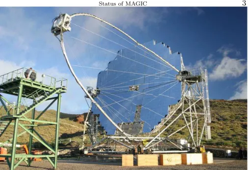
Figure 1. View of the MAGIC telescope right before its inauguration in October 2003. Its 17 m diameter reflector makes it into the largest Imaging Cherenkov Telescope in the world. The main mirror is composed of 940 1 m2 mirror panels that are fully steerable using an active mirror control system.
completed (December 2001). In fact, the assembly of the whole frame took only one month because of a construction based on the so-called tube and knot system of the company MERO.
The telescope drive system of the alt-az was installed during 2002.
The azimuth axis is equipped with two 11 kW motors, while the el- evation axis has a single motor of the same power. The position of the telescope is measured in the mechanical telescope frame by three absolute 14-bit shaft encoders. With this configuration it is possible to measure the telescope position with an accuracy of about 0.02
◦. The maximum repositioning time of the telescope is 22 seconds, well below the 30 seconds target required for gamma ray burst follow-up. By using a CCD camera mounted on the reflector frame we have established that the telescope tracks to better than a 1/10 of a pixel size.
2.2. The Reflector
The overall reflector shape is parabolic to minimize the time spread
of the Cherenkov light flashes in the camera plane. The preservation
of the time structure of the Cherenkov pulses is important to increase
the signal to noise ratio with respect to the night-sky background light
(NSB). The dish is tessellated by 956 0.5 × 0.5 m
2mirrors covering
a total surface of 234 m
2. Each mirror is a sandwich of aluminium
honeycomb on which a 5 mmm plate of AlMgSi1.0 alloy is glued. The aluminium plate is diamond-milled to achieve a spherical reflecting sur- face with the radius of curvature that is more adequate for its position in the paraboloid. A thin quartz layer protects the mirror surface from aging. The reflectivy of the mirrors is around 90%. The alignment of the mirrors in the telescope surface has been done using an artificial light source at a distance of 960 m. The overall spot has a FWHM of roughly half a pixel size (< 0.05
◦).
2.3. The Active Mirror Control
A large diameter telescope has strong requirements on the stiffness of the reflector frame. When directing the telescope to different eleva- tion angles the reflector’s surface deviates from its ideal shape under gravitational load. Two solutions are possible to counteract the de- formations: a) either to construct a very heavy and stiff frame or b) allow for small deformations by constructing a light-weight structure and correct its mirror profile. We have chose the second option for the MAGIC telescope and equipped the reflector with an “Active Mirror Control” system. Each four mirror facettes are mounted on a single panel. Two of the three mounting points of the panel are equipped with actuators which can be used to adjust its position on the frame.
The main elements of each actuator are a two-phase stepping motor (full step 1.8
◦, holding torque 50 N cm) and a ballspindle (pitch 2 mm, maximum range 37 mm). In the center of the panel a laser module is pointed towards the common focus of the four mirrors. The panels are aligned using the artificial light source, the positions of all the laser spots are recorded and can be used as a reference to re-align them for each elevation angle. The AMC has undergone extensive tests during winter 2003/04 and it is presently close to its nominal performance.
The light spot of bright stars focussed at infinity fit within one pixel (RMS of the Point Spread Function less than 0.1
◦).
2.4. The Camera
The MAGIC camera has 1.5 m diameter, 450 kg weight and 3-4
◦FOV.
The inner hexagonal area is composed by 397 0.1
◦FOV hemispherical photomultipliers of 1 inch diameter (Electron Tubes 9116A(Ostankov et al, 2000)) surrounded by 180 0.2
◦FOV PMTs of 1.5 inch diameter (ET 9116B, see figure 2.4a). The time response FWHM is below 1 ns.
The photocathode quantum efficiency is enhanced up to 30% and ex-
tended to the UV by a special coating of the surface using wavelength
shifter (Paneque et al, 2000) (see figure 2.4b). Each PMT is connected
to an ultrafast low-noise transimpedance pre-amplifier, the 6-dynode
Figure 2. On the left a view of the telescope camera with its 577 PMTs. The inner section of the camera is made up of 397 0.1◦ field-of-view pixels, surrounded by four rings of 0.2◦ pixels. The second picture shows two Electron Tubes PMTs. The
“frosted” PMT on the right has been been coated with a wavelength shifter lacquer that increases the quantum efficiency by 30% (coating all the PMTs is roughly equivalent to increasing the mirror area from 240 m2 to 300 m2.)
high voltage system is stabilized with an active load. Dedicated light collectors have been designed to let the photon double-cross the PMT photocathode for large acceptance angles. The anode current and HV are read out for each pixel and digitized by a 12 bit ADC. The temper- ature and humidity are controlled by a water based cooling system.
The camera was completed in summer 2002 after extensive testing and characterization; it was installed on the site in November 2002 and commissioned in March 2003. First starlight using the DC current readout was recorded already on 8th of March 2003. In the last year the camera has complied with its expected performance.
2.5. The Readout System
The PMT signals are amplified at the camera and transmitted over
162 m long optical fibers using Vertical Cavity Emitting Laser Drivers
(VCSELs, 850 nm wavelenght). Transmission over optical links drasti-
cally reduces the weight and size of the cables and protects the Cherenkov
signal from ambient electromagnetic noise in the line. In the receiver
boards in the electronics room the signal is amplified and split. One
branch goes to a software adjstable threshold discriminator that gen-
erates a digital signal for the trigger system. The signal in the second
branch is stretched to 6 ns FWHM and again split into a high gain line
where it is further amplified by a factor ∼ 10 while the low gain line
is just delayed by 50 ns. If the signal is above a preset threshold both
lines are combined using a GaAs analog switch and digitized by the
same FADC channel.
The 8 bit 300 MHz Flash ADCs continuously digitize the analog signals and store the digital data into a 32 kByte long ring buffer. If a trigger signal arrives within less than 100 µs the position of the signal in the ring buffer for each pixel is determined and for each pixel 15 high gain plus 15 low gain samples are written to a 512 kByte long FIFO buffer at a maximum rate of 80 Mbyte/s. The readout of the ring buffer results in a dead time ∼ 20 µs. This corresponds to about 2% dead time at the design trigger rate of 1 kHz. The time and trigger information for each event are recorded by dedicated digital modules which are read out along with the FADC analog modules. The readout is controlled by an FPGA (Xilinx) chip on a PCI (MicroEnable) card. The data are saved to a RAID0 disk system at a rate up to 20 MByte/s which results in up to 800 GByte raw data per night.
2.6. The Trigger
MAGIC is equipped with a two-level trigger system with programmable logic (Bastieri et al, 2001). The first level (L1T) applies tight time coincidence and simple next neighbour logic. The trigger is active in 19 hexagonal overlapping regions of 36 pixels each, to cover 325 of the inner pixels of the camera. The second level (L2T) can be used to perform a rough analysis and apply topological constraints on the event images. Using for instance a fast evaluation of the size of the Cherenkov image it is possible to reduce significantly the NSB, thus allowing a reduction of the discrimination level and the gamma ray threshold. The individual pixel rates of the channels included in the trigger are monitored using 100 MHz scalers.
The 1st and 2nd level trigger systems were installed and commis- sioned during 2003 as well as the whole computing system for the telescope control and DAQ.
2.7. The calibration system
The calibration system consists of a light pulser and a continuous light
source (both situated in the center of the mirror dish), a darkened, sin-
gle photoelectron counting PMT (“blind pixel”), located in the camera
plane and a calibrated PIN-diode 1.5 meter above the light pulser. The
pulsed light is emitted by very fast (3-4 ns FWHM) and powerful (10
8-
10
10photons/sr) light emitting diodes in three different wavelenghts
(370 nm, 460 nm and 520 nm) and different intensities (up to 2000-3000
photoelectrons per pixel and pulse). It is threfore possible to calibrate
the whole readout chain in wavelength and linearity. The continuous
light source consists of LEDs simulating the NSB at La Palma with
different intensities. The light pulser and continuous light source were
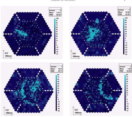
Figure 3. Displayed are several real events that are good candidates for aγ-ray (top, left), a hadron (top, right), a hadron + muon (bottom, left) and an isolated muon (bottom right).
commissioned during the winter 2003/04, while the blind pixel and PIN diode are currently in their commissioning phase.
3. First Data
3.1. Performance
During the winter we have reached the expected performance of most of the systems in the telescope. We are presently working on the evaluation of the global performance of the instrument.
Muons generate very well defined rings in the camera that are used
to calibrate the telescope and to derive the point spread function of the
reflector. See for instance the event display in the bottom right panel
of figure 2.
The point spread function can also be derived by means of the distribution of pixel anode currents of bright stars. In addition the distribution of currents allows us to monitor the intensity of the NSB in the field of view. NSB generates about 1 photoelectron RMS per 3.3 ns FADC sample in the inner PMT pixels. We also make use of anode currents to estimate the mispointing of the telescope and to crosscheck the absolute position of the source.
The telescope trigger rate has been found to vary smoothly with the discrimininator threshold level as expected if it is dominated by cosmic rays and not by night sky background noise. This happens for all multiplicities of the trigger (3, 4 and 5 next-neighbours pixels). Most of our data have been recorded with a threshold level around 4 phe and 4 NN trigger multiplicity.
The arrival time of the Cherenkov pulses to the different pixels in the camera can be determined with a precision better than 1 ns. This allows to characterize the time profile of the shower and gives another handle to estimate the direction of the incident γ -ray.
The dead time of the system has been calculated from the time difference of consecutive events and is well within the specifications of the readout system (less than 0.1%).
3.2. Data Sample and Analysis
It is worth to note that the telescope is still in its commissioning phase.
All the results presented here are preliminary since the configuration and performance of the telescope are not the nominal ones yet and the analysis software is still in its development phase.
In the months ellapsed since the inauguration of the telescope, we have mainly concentrated on low zenith angle (<40
◦) observations of standard TeV candles like Crab Nebula, Mrk 421, Mrk 501, 1ES 1426 and 1ES 1959. A roughly equivalent amount of OFF source data have been recorded under the same conditions of the ON data for background substraction.
We have selected only very short data samples for which the weather conditions were excellent on the basis of the trigger rates and star extinction measurements, all the telescope hardware systems were per- forming nominally and the data have been already preprocessed and calibrated.
The calibration of the telescope has been performed mainly using
the so-called F-Factor method: the number of photoelectrons produced
by the light pulser in a pixel are estimated using the width of the
charge distribution recorded by the FADCs. Images are cleaned using
two levels (tail and boundary cuts).
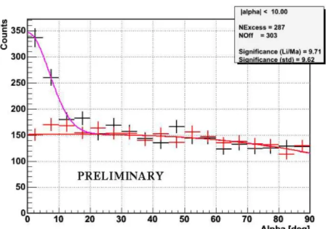
Figure 4. First detection of the Crab Nebula using the MAGIC telescope.
We have applied a standard analysis based on Hillas parameters.
Cuts on WIDTH, LENGTH and DIST have been optimized on a small sample of the data and then applied to the whole sample. The cuts are dynamical, that is, they scale with the size of the shower. Any mispointing of the telescope has been corrected using reference stars in the anode currents and the “false source method” where the standard Hillas analysis is performed in a grid of positions in the camera field of view.
A lower cut on the shower size of 2000 photons has been applied.
This cut selects only high energy showers for which a standard anal- ysis based on the Hillas parameters is straightforward. However this increases substantially the analysis threshold as respect to the trigger threshold.
3.2.1. Crab Nebula
The Crab Nebula is a steady emitter at GeV and TeV energies. The γ -ray emission is produced by Inverse Compton (IC) scattering of a population of electrons that are accelerated in the plerion around the central pulsar. The spectrum of this source has been measured in the GeV range by EGRET and at energies above 300 GeV by a number of Cherenkov telescopes. The expected level of emission between 30 and 300 GeV makes it into an excellent calibration candle for MAGIC. The spectrum in this energy range is interesting by itself since it allows to further constrain the IC emission parameters (magnetic field and/or size of the emission region).
Crab was observed during the winter months for about 20 hours
under very different weather and instrumental conditions. We have
selected a sample of Crab Nebula data of 60 minutes livetime at low
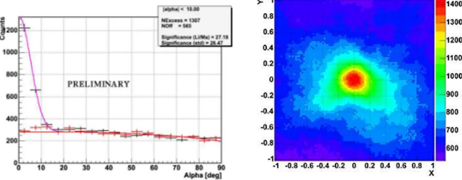
Figure 5. Left: Alpha plot for the selected sample of Mrk 421 data (2004/03/15).
Right: Result of the false source analysis of the Mrk 421 data sample.
zenith angle. Fig. 3 displays the distribution of the ALPHA Hillas parameter for the ON and the corresponding OFF data. An excess is clearly visible at low ALPHAs. We detect 290 gamma candidate events over an expected background of 300 events. This corresponds to a significance of ∼ 10σ.
3.2.2. Mrk 421
Mrk 421 is one of the so-called TeV BL Lacs that have been detected above 500 GeV. It undergoes the fastest flares that have been observed at these energies, with flux doubling times as short as 20 minutes. The very high energy emission is attributed to IC scattering of electrons that are accelerated in the base of the jet. The IC peak of the spectral energy distribution is probably around ∼ 100 GeV. During 2004 the source has undergone an episode of intense flaring in X-rays. Since the correlation between the X-ray and the high energy emission is well established, this source was also an excellent candidate for MAGIC.
The 2004 observation campaign started on January and finished on May. A simple online analysis running on site has shown clear evidence for signals during most of the campaign. MAGIC also joined a multiwavelength campaign with VERITAS and RXTE in May 9th.
The data are still not available for full analysis but again showed a significant signal in the online analysis.
Here we present the results of a small sample of 96 minutes in opti-
mal conditions in the night of March 14/15 2004. Fig. 4 (left) shows the
pointing angle “alpha” distribution for these data and the correspond-
ing OFF source data. A total of 1307 excess events are observed over
an expected background of 565 events. The significance of the detection
3.2.3. Further Progress
An estimate of the energy threshold of the telescope during this ob- servation of the source’s γ-ray flux is under way. We are working to improve the significance and the excess of the detection by reducing the analysis threshold energy and by applying optimized cuts on other parameters and using the Cherenkov pulse time profile. These data will be complemented soon with the analysis fo the full sample that has been recorded during the last months.
4. Future Instrumental Developments
MAGIC as it stands now has always been thought as the first of a series of instruments aimed at reducing the energy threshold and increasing the sensitivity in the GeV energy range.
The second instrument in this series is already under construction and will have a reflector of the same size of MAGIC, but will incor- porate a number of new techniques that will improve its performance (Mirzoyan et al, 2003). Among them is a faster digitizing system (with
>2 GHz sampling rate) is in its latest stage of development. We are also working on several light detectors with increased efficiency (HPDs and arrays of Geiger mode SiPM) that may be incorporated in the camera of the second telescope or even in the original MAGIC telescope. The frame for the second telescope is already under construction and will be delivered to La Palma in 2005.
The third instrument is ECO-1000 (Merck et al, 2003; Baixeras et al, 2004), a Cherenkov telescope with 1000 m
2reflector surface (roughly four times larger than MAGIC). ECO-1000 intends to take the Cherenkov Telescope technique to its extreme and reduce the threshold down to 5 GeV with a sensitivity of ∼ 3 · 10
−10cm
−2s
−1. This is an energy range where it fully overlaps detectors on board satellites like GLAST.
Due to its large collection area and high flux sensitivity, ECO-1000 is
the ideal instrument to complement GLAST’s huge field of view in the
study of transient sources.
5. Conclusions
MAGIC, the very large new-generation IACT designed specifically for the exploration of the 10-300 GeV gamma energy gap is in its final commissioning phase and is expected to enter regular operation after the summer.
So far all the new technical components are working with their nominal performance, and are now undergoing extensive checks. The telescope has already detected two very high energy sources, Crab and Mrk 421, with high significance.
We can conclude that MAGIC is well on its way and entering the discovery phase. The next months will show the full potential of the lowest energy threshold Cherenkov telescope ever built.
Acknowledgements
We would like to thank the IAC for excellent working conditions. The support of the Italian INFN, German BMBF and Spanish CICYT is gratefully acknowledged.
References
Baixeras C. et al. Design studies for a European Gamma-ray Observatory. Preprint astro-ph/0403180
Barrio J. A. et al. The MAGIC Telescope Design report. MPI Institute Report MPI-PhE/98-5 (March 1998).
Bastieri D. et al et al. A two level pattern trigger for the MAGIC telescope. Nuclear Instr. and Meth. A, 461:521–523, 2001.
Lorenz E. et al. The MAGIC telescope project based on a 17 m Diameter Parabolic Solar Concentrator. Procs. Workshop: Towards a Major Atmospheric Cherenkov Detector IV, Padova, Italy. Ed. Cresti M. (1995) 277.
Merck M. et al. Extending The Cherenkov Technique Down To An Energy Thresh- old of A Few GeV: The Ultimate Instrument For Ground-Based Gamma-Ray Astronomy. Proc. International Cosmic Ray Conference, Tokyo, 2003.
Mirzoyan R. et al. Technical Innovations for the MAGIC project. Proc. International Cosmic Ray Conference, Tokyo, 2003.
Ostankov A. et al. A study of the new hemispherical 6-dynode PMTs of Electron Tubes. Nuclear Instr. and Meth. A, 442:117–123, 2000.
Paneque D. et al. A method to enhance the sensitivity of photomultipliers for Air Cherenkov Telescopes. Nuclear Instr. and Meth. A, in press.