Summary Project Plan for the Tangram project on
Model-based Testing
Authors:
Tom Brugman, ASML
Frans Beenker, Embedded Systems Institute Document status: Approved
Document release date: January 31, 2003
Distribution list:
Embedded Systems Institute Tangram project internet site Document History
Version Status/ Date Description of changes
01 Proposal / 140103 Creation of the document on basis of approved Tangram project plan 02 Approved / 310101 Approved version.
Table of contents
1. INTRODUCTION... 3
1.1. THE PROJECT... 3
1.1.1. Technical domain description ... 4
1.1.2. Application domain description... 4
1.1.3. Summary of project objectives and intended results ... 5
1.1.4. Summary of project approach ... 7
1.2. PROJECT CONSORTIUM... 8
1.3. REFERENCES... 9
1.4. ABBREVIATIONS AND DEFINITIONS... 9
2. MULTI-PARTNER PROJECT CONTEXT ... 10
2.1. PARTNER’S STRATEGY AND FIT WITH THE TANGRAM PROJECT... 10
2.2. A NEED FOR CO-OPERATION OR WHY 1+1=3... 13
3. TECHNOLOGICAL INNOVATION ASPECTS ... 14
4. PROJECT SCOPE ... 15
4.1. PROBLEM TRANSLATED TO LINES OF ATTENTION... 15
4.2. THE ASML PROJECT CASE APPROACH... 15
4.3. INTENDED RESULTS... 16
4.3.1. Background knowledge... 16
4.3.2. Global description of foreground knowledge ... 16
5. PROJECT EXECUTION... 17
5.1. OVERALL PLAN WITH MAJOR MILESTONES AND DECISION MOMENTS... 17
5.2. ACTIVITIES WITHIN AND OVER THE LINES OF ATTENTION... 17
5.2.1. Line of Attention 1: Test Strategy ... 17
5.2.2. Line of Attention 2: coupling simulation and test environment ... 19
5.2.3. Line of Attention 3: Test generation, automation, and regression testing... 23
5.2.4. Line of Attention 4: Diagnosis... 25
5.3. KNOWLEDGE SHARING AND KNOWLEDGE TRANSFER... 27
1. INTRODUCTION
1.1. The project
Industrial systems are becoming highly dependent on software modules. This results in a continuous increase of both development & test effort and maintenance & upgrading effort of innovative products.
To limit this trend of increasing cost, time, and team size, research is required that targets on improving development and test methodologies, processes, and supporting tools.
This project focuses on the improvement of the test strategies for high-technology embedded systems.
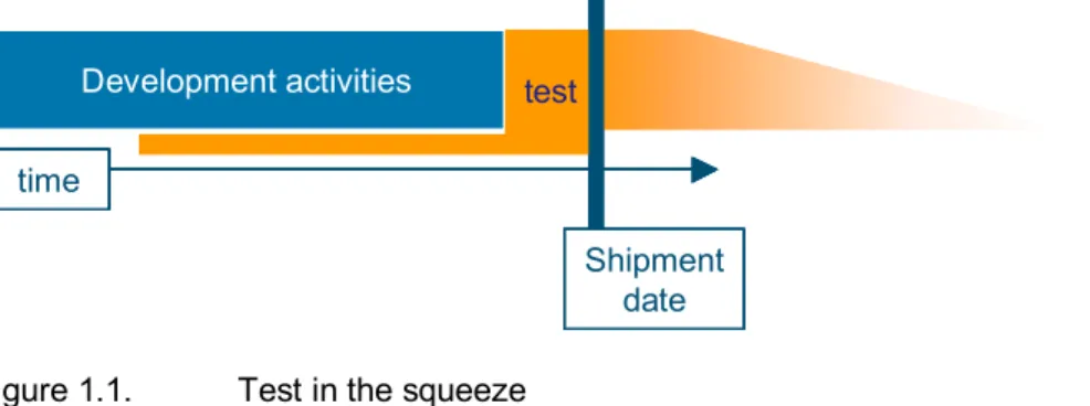
Testing is considered an integral part of product development, and testability is considered as one of the system architecture viewpoints; see [ieee1471, muller-gaudi]. Via an application focus, the test strategy is optimized towards an application in a certain product/market combination. In this project, the system and application focus is on ASML wafer scanners as a case to focus the innovative research. The main characteristics of embedded systems in general and the ASML wafer scanners in particular are the complexity of all technology aspects (mechanics, optics, physics, electronics, software) and the importance of time to market. This leads to high-risk technology breakthrough development projects where the gap between “all functionality available” and “first shipment date” is very short. This puts test activities in a very interesting bottleneck position; see Figure 1.1.
Figure 1.1. Test in the squeeze
It is very difficult to guarantee sufficient quality in such a complex development environment when there is hardly any time left for test activities at the end of the development process. The only feasible route is in concurrent engineering – perform the test activities in parallel with the development activities; see Figure 1.2. Exploring this route for complex embedded systems such as the ASML wafer scanner is the main driver and goal of this project.
Figure 1.2. Concurrent development and test engineering
Whereas many national and international product development research activities focus on the creative aspects of specifying, designing, and implementing systems, only a small percentage of these groups are active on the reverse aspects of testing the result against its intended functionality.
Testability concepts, especially software test and system integration test concepts are a white spot on many research agendas. In research agendas such as “Embedded, Everywhere”, see [embev], the test issue is hardly addressed. The Dutch Progress Embedded Systems roadmap though states test as an important aspect and addresses the problem that so far hardware and software have totally different views on testability issues and use a totally different terminology; see [Progress].
Development activities
time
Shipment date test
Development activities
time time
Shipment date test
Development activities time
test
Shipment date Development activities
time
test
Shipment date Development activities
time time
test
Shipment date
In view of the fact that the cost of testing complex systems has grown up to 30-50% of the total development costs, the challenges and opportunities of this project become clear. Considering the huge development costs of these systems, the test costs are tremendous. Besides the cost of testing during development, also the costs of being late on the market due to quality problems or additional costs due to long repair times or short times between failures go sky-high.
It is expected that most of the results of this project are generically applicable for many other types of embedded systems. Therefore, special attention is given to knowledge transfer and to phrasing the results in a generic manner.
The project is carried out under the project management responsibility of the Embedded Systems Institute. To a maximum extent, the project participants are co-located, i.e. they work at a single location. It depends on the project phases and the actual circumstances of the project participants, where the actual location is.
1.1.1. Technical domain description
Considering the value of product (system) ownership, expressed in terms of customer satisfaction and cost per function, controlling reliability of the product and controlling quality cost in product development becomes a major challenge. The continuous and rapidly increasing complexity of systems and the severe time to market requirements are forcing the high-technology industry to search for ways through technologies, processes, methodologies, and supporting tools to improve the quality of the systems they develop and deliver. A critical link in the overall development process is the test process as a whole and test as an activity, both during development and, if inevitable, at customer site.
Scheduling test activities and balancing test cost with quality is difficult. An overall experience is that quality problems discovered late in the product life-cycle necessitate expensive fixes (often done by the most experienced system engineers) and lower the customer satisfaction due to an increase of unscheduled down time of the system, increase of mean time to repair and decrease of mean time between failures. The trap easily fallen into is that at time of specifying the next generation system, the experienced system engineers are occupied in analyzing and repairing errors in previous releases, often at customer site.
Considering embedded systems such as the ASML wafer scanner, with their complexity in its multi- technology aspect of software, electronics, mechanics, physics, etc. it is impossible to test the system for 100% according to all its specifications and customer expectations. It is unrealistic to assume that all requirements are defined in a clearly and mutually consistent way and would remain constant over time. Consequently, choices have to be made on where to put the test focus, meanwhile the reference model for testing is incomplete and inconsistent. This choice in choosing the right balance is guided by product quality and test time/test cost. For every high-technology company, this choice might be different.
Building high quality and reusable multi-technology components with a clear strategy on integration testing has become very important. The testability of these components (i.e. the level to which it can be tested with minimal cost) is one of the important factors determining the quality of a component.
The same holds for an integrated set of components, and ultimately the complete system. The questions then become what is testability, how to break down (and build up) a system into testable components, how to evaluate testability, how to measure test effectiveness and test quality, how to generate test cases and execute them, how to diagnose the root cause of failure, etc.
1.1.2. Application domain description
Modern, complex integrated circuits (ICs) consist of many interconnected pattern layers of different materials on top of a silicon base. These patterns are produced on silicon wafers by means of photolithography to create the pattern image. Different techniques, like etching, diffusion and ion beam implanting are used to create the actual pattern logic. A wafer scanner performs the lithographic
production step. A wafer scanner projects an image onto a thin layer of resist on the wafer. Key parameters in this step are the minimum structure size (Critical Dimension) and the relative position accuracy (Overlay) of the different layers. Current state of the art Critical Dimension is in the order of 130nm, with roadmaps down to the range of 30 nm. In order to position the wafers with respect to the optical system, and to project an image on the wafer with extreme accuracy and high throughput, many different tasks have to be performed as efficiently as possible and with the shortest processing time possible.
The ever-decreasing Critical Dimension results in increasing cost and complexity of lithographic tools.
As a result, the competitiveness of these tools also depends strongly on the percentage of non- scheduled down time at a customer site, and therefore on the quality and reliability of operation. The high level of innovation in the semiconductor business results in a high level of innovation in the lithographic tools. Also, due to the high profits associated with the latest technologies, short Time To Market is crucial for profitability.
Semiconductor manufacturing technology, and especially lithography, is getting more and more expensive. Introduction of new technologies is requiring ever-increasing huge investments. The time to obtain a return on this investment is stable or decreasing. The consequence is that there is a strong need for reliable products, both for the equipment supplier (e.g. ASML) and the semiconductor manufacturer. For example, the International Technology Roadmap for Semiconductors (ITRS); see [ITRS] states that the availability of equipment raises from 85% in 2001 to 95% in 2006, and that the fab ramp up time decreases from 4 to 2.5 months.
1.1.3. Summary of project objectives and intended results
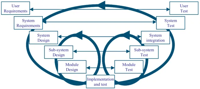
Test objectives such as checking that a product works according to its specifications and expectations and analyzing the cause of failure are often mapped onto the various product development stages and product quality requirements; see Figure 1.3.
Figure 1.3. The V-model: test activities put into perspective.
The product development stages range from system requirements specification to system design, to ultimately implementation. These stages are indicated on the left of the so-called v-diagram in Figure 1.3. Mostly, this process is not a simple waterfall model. Often iterations take place and incrementally the system is constructed. Extensive testing follows the specification, design, and implementation phases. Following the development, testing takes place in several stages; each stage having a separate focus area such as modules, sub-systems, the system, and the intended customer use.
Progressing along all test phases builds up the confidence that all parts of the system and ultimately the complete system function correctly.
If all test activities would not start until the complete system has been implemented, then test would be a real barrier for early product shipment. Hence, it is our approach to start testing as early as possible, and to have multiple development and test activities taking place at the same time. This causes both
System Requirements
System Design
Sub-system Design
Module Design
Implementation and test
Module Test
Sub-system Test
System integration
System Test
User Test User
Requirements System Requirements
System Design
Sub-system Design
Module Design
Implementation and test
Module Test
Sub-system Test
System integration
System Test
User Test User
Requirements
an incremental process and a concurrent development & test process. In itself, this is a complicated process to manage.
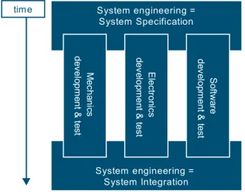
Next to a concurrency in development and test activities, there is a second concurrency in disciplinary activities such as mechanics, electronics, and software; see Figure 1.4.
Figure 1.4. Concurrency in disciplines..
The test methodologies for mechanics and electronics are well advanced and a lot of research is performed worldwide. For example, well known methods for Printed Circuit Boards such as boundary scan (see [bounscan]) are standardized. The same holds for test methods for software such as reviewing and inspection, exhaustive table-driven testing, memory-leakage testing, etc. In this manner, testing is organized along the technology axis. However, testing becomes complicated (and crucial in terms of risk management) when multiple technology axes cross each other, which is the case for integration of multi-technology components up to the complete integrated system. Only after integration, for example, the real performance of the system can be measured. It is then when the real consequences of architectural choices become visible. It is there where we put the focus of the project.
The prime project objectives are the following;
Define a test methodology with supporting processes and tools, which provides a right balance between product quality, product reliability, test schedule and test cost in order to optimize on return on investment.
This test method should have the following characteristics:
o Focus on software testing and multi-technology integration testing.
o Coupling to a testability viewpoint on system architecture.
o Via an approach of integrating testable components enable and support an early start of the test and integration activities in the development process.
o Use automation where applicable.
o Allow for diagnostic capabilities for the difficult problems.
o Maintain an obtained test quality in a continuous changing environment.
It is explicitly stated that the results of our study and experiments are in the area of proof-of-concept of methodologies and tools and are by no means at the level of product quality. Achieving product feasible results out of the project results requires substantial additional effort within ASML and/or other project partners. Integrating the project results into an industrial application requires much attention, which is outside the project scope.
System engineering = System Integration System engineering =
System Specification
Mechanics development & test Electronics development & test Softwaredevelopment & test
time
System engineering = System Integration System engineering =
System Specification
Mechanics development & test Electronics development & test Softwaredevelopment & test
time
1.1.4. Summary of project approach
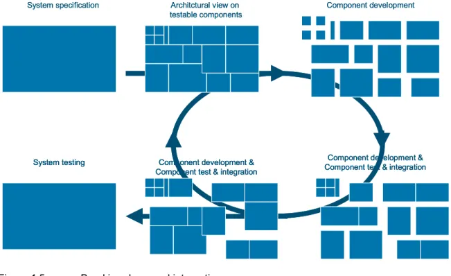
Testability of embedded systems has everything to do with breaking-down the system into testable components and taking care that both the individual component can be tested and an integrated set of testable components can be tested. This ultimately leads to a testable system; see Figure 1.5.
Figure 1.5. Breaking-down and integration.
Whether a component is software, hardware, electronics, or a combination thereof does not make any difference. Considering that each individual technology has its own test methods, we focus on multi- technology component definitions.
A breakdown into testable components is seen as a testability view of the system architecture and has to be defined early in the system architecting phase. This view not only defines the hierarchy of testable components, it also defines the multi-technology integration steps from developed components into the complete system.
For each component, an optimal test method is chosen. Criteria for test method selection can be based on risk management, test effort, required test quality, impact on time to market, etc. The focus of testing may be different for each component; e.g. functionality, performance, safety, etc.
Once a component has been tested, the next question is what to do when this component is integrated with other components; see Figure 1.6. We take a maximum use of the fact that components have already been tested to a certain extent. An additional complexity is that some components have not been implemented yet. To enable further integration testing with available functionality, some of the components need to be simulated, interfaces need to be stubbed, etc. In this manner, a component can be tested in its intended environment.
The simulations are developed from suitable models of the components. This is a form of model- based simulation in which different technologies can use different types of models.
Component development
Component development &
Component test & integration Component development &
Component test & integration System testing
System specification Architctural view on testable components
Component development
Component development &
Component test & integration Component development &
Component test & integration
System testing Component development &
Component test & integration Component development &
Component test & integration System testing
System specification Architctural view on testable components
Figure 1.6. Integrated components.
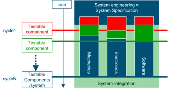
A multi-technology testing process has a direct relationship with the development process. It requires synchronization between the various development teams in terms of available functionality, in order to have it fit into the systems architectural view on testing, see Figure 1.7.
Figure 1.7. System integration integrated into multi-disciplinary development.
The cycle of testing multi-technology components is repeated each time a new set of functionality becomes available. At that moment of time, the test process is repeated at a next level of multi- component increment. Ultimately, this leads to a testable and tested system.
The term “repeated” indicates also that some parts of the process allow for a regression type of testing, with automation possibilities. For automatic test generation, similar models are used as for simulation. We expect that automatic model-based test generation can also be applied to other types of tests than regression testing.
The models that are used for simulation and test generation can also be exploited to improve the process of fault diagnosis. Such a model-based diagnosis is expected to be especially effective in finding faults that are at the boundaries of different technologies.
1.2. Project consortium
In this project, a competent consortium works together; see Table 1.1.
Partner Department
ASML Sw engineering, system engineering
NLR Embedded Systems
Delft University of Technology Faculty of Information Technology and Systems Component A Component B
?
Component A Component B?
? ?
System Integration System engineering =
System Specification
Mechanics Electronics Software
time
Testable component
Testable component
Testable Components
/system cycle1
cycleN
System Integration System engineering =
System Specification
Mechanics Electronics Software
time
Testable component
Testable component
Testable Components
/system cycle1
cycleN
(TUD)
TNO/TPD Embedded Systems Development
Twente University (UT) Faculty of Computer Science
University of Nijmegen (KUN) Nijmegen Institute for Computer and Information Sciences (NIII) - Software Technology Research Group (ST) Eindhoven University of
Technology (TU/e)
Faculty of mechanical engineering, Group Systems Engineering
Eindhoven University of
Technology (TU/e) Faculty of mathematics and computing science, Formal methods group
Science & Technology Embedded Systems Institute Table 1.1. Project consortium.
1.3. References
[Porter-innovationlecture] Innovation lecture 2001, Ministry of Economical Affairs
[CIC-nota] Concurreren met ICT-competencies, Beleidsnota, Ministerie van Economische Zaken, Ministerie van OCenW, april 2000.
[ieee1471] IEEE-Std-1471-2000, Recommended Practice for Architectural Description of Software-Intensive Systems
[Muller-gaudi] http://www.extra.research.philips.com/natlab/sysarch/
[embev] Embedded, Everywhere, Embedded, Everywhere: A Research Agenda for Networked Systems of Embedded Computers,
http://www.nap.edu/catalog/10193.html
ISBN:0-309-07568-8, Library of Congress Catalog #2001-093511.
Available from
http://www7.nationalacademies.org/cstb/pub_embedded.html [Progress] Embedded Systems Roadmap, available from
http://www.stw.nl/progress/ESroadmap/index.html
[ITRS] International Technology Roadmap for Semiconductors
http://public.itrs.net/
[bounscan] IEEE Standard Test Access Port and Boundary-Scan Architecture, IEEE Std 1149.1-1990, available from
http://standards.ieee.org/reading/ieee/std_public/description/testtech/
1149.1-1990_desc.html
[Bos 1998] A. Bos. Choosing the Right Model, PhD thesis, Delft University of Technology, The Netherlands. 1998.
[S&T 2000] A. Bos, A. van Gemund, and C. Witteveen. Model-based Diagnosis Support for Satellite-based Instruments.In IEEE Autotestcon, Systems Readiness Technology Conference, Anaheim CA, September 2000
1.4. Abbreviations and definitions
ESI Embedded Systems Institute
LoA Line of Attention
Tangram Test Approach based on iNtegrated product Generation and product Realization applied to Asml Machines
ITRS International Technology Roadmap for Semiconductors
2. MULTI-PARTNER PROJECT CONTEXT
2.1. Partner’s strategy and fit with the Tangram project
Per project participant, a description of their strategy is given. We argue why the Tangram project fits with each participant’s strategic direction.
ASML
ASML has a very strong system engineering and architectural focus in all disciplines, and has shown to be able to integrate complex technology from a wide range of disciplines. Continuously, ASML is focused on lowering cost of ownership of their products and improving the customer relationship. It is the strategy of ASML to closely follow the International Semiconductor Technology Roadmap and to be the first on the market for allowing their customers to quickly introduce the latest manufacturing processes.
Currently ASML advanced customers are introducing manufacturing processes with 100 nm feature sizes. Work in R&D is going on producing the next generation. These machines are a complex collection of electrical, mechanical and optical parts “glued” together and controlled by very complex software. Currently the testing and improvement of this software is taking a considerable amount of time and resources.
The Tangram project therefore fits the ASML strategy and needs.
NLR, Embedded Systems Department
The mission of the Information and Communication (ICT) Division of NLR, to which the embedded systems department belongs, is to provide high quality information systems, mathematical methods and models, consultancy and services in the ICT area to organizations in the aerospace area and related high-tech fields. Modern aircraft are complex systems, the software of which amounts to over 10 million lines of code. To cope with this complexity, while meeting time-to-market objectives, simulation is a key technique. As an example, “the Boeing 777 was completely planned with the aid of CAD techniques. Powerful graphics and mathematics software enabled the aircraft's creators to simulate every component of the plane in computers, ensuring that all the components fit together perfectly. The designers even simulated tests of the aircraft's flight capabilities under all conditions the craft was likely to encounter. Only after the simulated airplane was thoroughly tested construction begun”. Other examples of complex aerospace systems include Air Traffic Management (ATM) systems. These systems are quite large (containing around two million lines of code) and combine multi-domains like sensors, software, large displays, transmitters, radios etc.
NLR operates two large flight simulation facilities, and two large ATM simulation facilities.
Furthermore, NLR has developed tools to combine these simulators into one, networked simulation, which can be controlled and managed from a single location in the geographically distributed network.
Delft University of Technology, Faculty of Information Technology and Systems, Parallel and Distributed Systems Group
The Parallel and Distributed Systems group at TUD has a strong background in parallel and distributed programming language and compiler development, mobile computing, operating systems architecture, distributed systems scheduling, and performance modeling. A long-term strategy is to widen the language and compiler expertise from the area of (parallel) algorithm specification to the systems specification language area that covers generating entire systems (hardware and software) from application specifications. Notable examples are model/specification based generation of special- purpose hardware as well as diagnostic embedded software.
For the Parallel and Distributed Systems group the Tangram project provides an important step in the long-term strategy aimed at performing a leading role in system specification languages and associated compilers. The ASML problem provides an extremely challenging case that comprises all aspects present in extremely complex, real-world specification problems, including concurrency, state,
time, hierarchy, uncertainty, involving different domains such as the software, electrical, physical, and mechanical domain.
TNO-TPD
TNO TPD is one of the 14 institutes of the Netherlands Organization for Applied Scientific Research TNO. TNO TPD aims to strengthen the competitiveness of its clients by innovative applications of technology. Technologies are: applied physics, informatics, optics, acoustics, mechanics, electronics, materials and process technology. Multidisciplinary project teams carry out the projects. Other knowledge centers, such as universities or other TNO institutes, are called in when additional expertise is required to solve a problem.
As a contract-research organization, TNO TPD aims to strengthen the competitiveness of its customers. TNO TPD believes that the best way to achieve this goal is to excel in a number of disciplines and their practical application in a variety of domains. Aiming at excellence in technology means meeting international state-of-the-art standards.
The goal of TNO is to act as an intermediary between the academic world and the industrial world. On one hand, it is TNO's task to translate new developments/trends occurring in the academic world into prototypes/product deliverables that shows a proof of concept. On the other hand, it is TNO's task to translate/guard the industrial requirements while developing such a prototype/product. The best way to achieve this goal is by building consortia with special interests to boost the knowledge transfer between the partners and to show the proof of concept.
Twente University, Faculty of Computer Science
The University of Twente (UT) mission statement includes the following characterization of the UT profile: "fundamental sciences and a strong orientation towards the development and application of new technologies [...] providing for societal needs" and "providing knowledge for societal service (consultancy, knowledge transfer, research)". An explicitly stated goal for the coming years is to achieve excellence and an entrepreneurial attitude in providing these services.
The high-priority research themes of the University of Twente are assigned to spearhead institutes that must achieve international prominence, operating at the European top-level in their domains. The Center for Telematics and Information Technology (CTIT) is the spearhead institute responsible for the field of Information Technology, including the research program of the Twente Embedded Systems Initiative (TESI). Its aim is to achieve and maintain excellence in this field as captured in the UT mission.
The proposed Tangram project combines state-of-the-art knowledge transfer from academia to industry with leading edge applied research. This fits the UT/CTIT strategy precisely.
University of Nijmegen, Software Technology Research Group
The Software Technology Research Group (ST) at the University of Nijmegen is part of the NIII - the Nijmegen Institute for Computer and Information Sciences - at the University of Nijmegen. The group currently has 15 employees. The central research theme of ST is the correctness of software. This involves correctness by construction as well as validation of correctness by means of testing. In both approaches the challenge of ST is to combine sound and well-defined theoretical foundations with high practical applicability and usefulness.
In the area of software testing the interest of ST is in methods, tools and applications of model-based testing. This concerns automatic, on-the-fly test generation from formal specifications, automatic test execution and analysis. ST is involved in the development and use of the model based test tool TorX Applications are found in safety-critical software projects, such as the payment component of a highway tolling system, and a storm surge barrier control system.
The objectives of the Tangram project perfectly fit within the research mission of the NIII - viz. to develop formal methods and tools for the construction of reliable software systems and components -, and within the research theme of the ST group, viz. to do research in methods, tools and applications of model-based testing aiming at the combination of sound and well-defined theoretical foundations with high practical applicability and usefulness.
Eindhoven University of Technology, Faculty of Mechanical Engineering, Group Systems Engineering
The Systems Engineering group aims to develop methods, techniques and tools for the design of advanced manufacturing systems. It focuses on manufacturing systems comprising multiple communicating subsystems that work in parallel. Such systems include: a multi-product flow line consisting of machines, robots and transport means; a batch plant consisting of reactors, tanks and pipes; a single production machine with a control system. Due to the increasing globalization of many product markets and the increasing complexity of manufacturing processes, these systems are typically characterized by: wide variety of products, many manufacturing processes or unit operations, a range of product routings, a rapidly changing product mix, process time variability, short cycle times, and flexibility. This requires a change in design philosophy from commonly used qualitative approaches to more quantitative and structured methods. The mission of the Systems Engineering group is to establish this change towards quantitative design methods by developing new concepts and computational tools inspired by mechanical engineering science, computer science and mathematics, and by applying these to selected problems from industry.
On the one hand, the Tangram project allows for the application of the methods, techniques and tools developed in the design process of complex manufacturing machines. On the other hand, it gives possibilities for extending these concepts towards testing and real-time analysis. Hence, this project will enable the analysis of more phases from the life cycle of a manufacturing system. Finally, our research domain area will be extended with, so-called, non-temporal performance aspects such as overlay and imaging quality.
Eindhoven University of Technology, Faculty of Mathematics and Computing Science, Formal Methods Group
The research group Formal Methods of the TU/e Division of Computer Science studies issues in computer science in a systematic and scientific way, based on solid mathematical principles. The area of Formal Methods concerns fundamental research and considers systems and constructions used in computer science. These constructions are described exactly in a formal syntax and are supplied with a formal semantics whenever appropriate.
Formal Methods increase understanding of systems, increase clarity of description and help solve problems and remove errors. Use of Formal Methods increases dependability and usability of constructions and systems in computer science.
We study and use Formal Methods in order to apply them. Thus, our choice of research topics is inspired by the practice of computer science. To support application, we use existing tools and develop new tools. We are not studying methods in isolation, but intend to have them used in practice.
One of the focus areas is testing. Applying formal methods in this area can lead to large improvements in system development. Building on our expertise gained in the STW Cote-de-Resyste project, and our cooperation with CMG, and related to our involvement in the ITEA TT-Medal project, this ASML project gives a unique opportunity to try out our approach in an industrial environment, and to learn what works and what doesn't.
Science & Technology
Science and Technology BV (S&T) is a software development company specialized in constructing so- called system health management software. Current activities in this area are mainly concentrated in the aerospace area (customers: ESA-ESRIN and ESA-ESTEC). S&T’s long-term strategy is twofold:
• Strengthen its position in application domains other than the aerospace domain, using its generic health management knowledge and experience.
• Improving its health management software construction capabilities by developing a generic tool set to specify, verify and generate health management systems (in particular, diagnosis systems).
For S&T this project gives ample opportunities to realize its long-term strategy. The ASML case allows S&T to realize a position as possible supplier of health management software in a market segment other than the aerospace, and to acquire essential knowledge required to construct a generic health management tool set.
Embedded Systems Institute
The Embedded Systems Institute has the ambition to improve and transfer the knowledge and skills of analyzing, specifying, designing, implementing and testing complex embedded systems. Furthermore,
it wants to acquire the position of expertise center, where professionals from both universities and industry can meet and debate, where lectures, courses and demos are given, and where an information center on embedded systems can be found.
The knowledge improvement ambition is realized by means of co-operative research projects in which interested parties work together on methods, processes, tools, etc. for embedded systems. The result of each project is transferred to interested parties for various purposes such as education and application. Results are made available by means of course material, technical reports, scientific publications, patent licenses, tools, educated and experienced personnel, etc.
To realize its ambition, the Embedded Systems Institute positions itself between the knowledge institutes and industry, and claims the management responsibility of all processes necessary to make the co-operative research projects work.
The Tangram project on integrated testing is one of the first projects in a series of embedded systems projects. To a maximum extent, the project organization utilizes a cross-fertilization profit of the co- existence of multiple projects.
The Embedded Systems Institute is a knowledge center for embedded systems. Through its research projects it combines disciplinary knowledge in universities and research centers with applied problem domains in industry. The knowledge and expertise on the integration and design of these systems is accumulated in the Embedded Systems Institute itself.
Two main characteristics of systems integration are increasing complexity and heterogeneity.
Scientific expertise in these two areas is vital to the existence of the Embedded Systems Institute.
This project addresses both characteristics
.
2.2. A need for co-operation or why 1+1=3.
Embedded systems always involve more than one discipline. Next to software, often mechanics and electronics are in place. A co-operation between these disciplines is required to obtain an optimal result. Test aspects have for a long time been of concern in hardware design and have been researched to a great extent. However, very little has been done in the area of software testing. The same holds for the integral aspects where software, electronics, and mechanics are integrated into a complete system. Co-operation between the disciplines is required to optimize the test approach in terms of choosing the right balance in quality, development lead-time, and cost.
The Netherlands has a long and impressive history in embedded systems. Where most of the software industry has disappeared to the US, we still have a strong position in embedded systems. Companies such as Philips Electronics, ASML, Océ, and many others, have worldwide a strong position. As pointed out in many documents, this situation needs careful attention; e.g. see [Porter- innovationlecture, CIC-nota]. To safeguard and strengthen our position, co-operation is required between all parties involved. This co-operation strategy also fits with the industrial strategy of strategic partnership.
3. TECHNOLOGICAL INNOVATION ASPECTS
For the following reasons, this project is considered to be a technological innovation project.
1. Heterogeneity. Modern embedded systems are inherently heterogeneous. In this project, we focus on the ASML wafer scanners, which combine aspects from physics, mechanical engineering, electrical engineering, and computer science. In this project, we want to combine these different disciplines from the start. This requires a thorough integration of different methods, techniques and tools. For instance, system modeling using continuous time concepts (aspects described using differential equations, typically used in e.g. mechanical engineering) needs to be combined with system modeling based on discrete-event systems (described using e.g. finite automata, typically used in e.g. computer science). Usually the multi-technology testing – if done at all -- is postponed until the final stages of system integration. The novelty of this project is that multi-technology testing is done right from the start of the development phase.
2. Early concurrent testing. From the start of system development, test activities are started up.
We want to construct a test environment, in which components can either be represented by mathematical models or by their implementations in software or hardware. System parameters should be taken into account from the start. When different tested components are put together, the aggregate should allow incremental testing. This allows testing in a different sequential order than the one in which components are developed. Components that have not been implemented yet are during testing replaced by model-based simulations.
3. Automatic test generation in heterogeneous systems. Automatic test generation is e.g. in computer science, a well-known activity. This project is novel in the sense that automatic test generation is, by means of model-based test concepts, applied to heterogeneous systems.
4. Quality assurance. During the design and manufacturing of the machine, the system is continuously evolving, due to modifications and new developments. By introducing the proposed way of working, namely early multi-technology testing, and by applying automatic test generation and test execution, the quality of the behavior of components is assured.
5.
Diagnosis. A crucial success factor in system design and operation is the possibility to apply fault diagnosis. Model-Based Diagnosis (MBD) represents the state-of-the-art in modern diagnostic technology. This approach allows diagnosis systems to be generated with much less effort. At present, even diagnostic applications based on MBD are practically limited to relatively small, mono-disciplinary systems of low complexity. The possibility of extending the application of MBD to highly complex, expensive systems opens up a singular opportunity for massive economic savings in system design and operational costs. The results of this project will therefore have a major impact on the cost/performance of the many, complex, expensive, and sometimes life- critical systems.Derived targets for the involved disciplines are the following.
1. Mechanical engineering. Use of model-based testing in the field of manufacturing systems engineering is a new methodology.
2. Electrical engineering. Merging of continuous time models and discrete-event models to obtain model-based as well as physical based testing.
3. Computer science and embedded systems. Early testing, out-of-order testing, multi- technology testing, and concurrent engineering.
4. PROJECT SCOPE
4.1. Problem translated to lines of attention
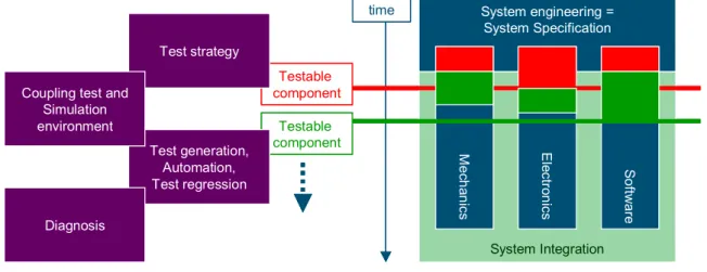
Referring to Figure 1.7, we distinguish four major lines of attention; see Figure 4.1.
Figure 4.1. Major project lines of attention.
The four Lines of Attention (LoA) of this project are the following:
1. LoA1: Test strategy: how to incorporate testability in both the architecture and the ASML working methods.
2. LoA2: Test simulation and verification models: how can modeling and simulation be applied to improve the quality of the delivered product?
3. LoA3: Test generation, test automation and regression testing: how can the quality of the tests be improved while minimizing the impact of the generation of tests, and how can the execution of tests be minimized while optimizing the quality of the tests?
4. LoA4: Diagnosis: how can the results of the tests be used to accurately isolate the cause of system failure and thus to minimize the system repair time?
All LoAs are multi-disciplinary. The testability and test activities have to be aligned with the discipline- oriented test methods. A total picture on test approaches, both from each single discipline, and multi- disciplinary, will be made available. This provides a route towards optimization of all test activities towards balancing test cost, scheduled activities, and product quality.
4.2. The ASML project case approach
To obtain focus, the project uses real-life ASML examples. Examples are subsystem and modules of the ASML scanner such as the wafer handler and reticle handler. These subsystems and modules are complex in terms of multi-technology integration problems. They provide excellent and challenging running vehicles.
The project primarily focuses on multi-disciplinary methods, tools and techniques to be used in the right part of the V-model (the test activities). In principle, the left part of the V-model is accepted as is and will only be extended or adapted with requirements from the test activities. It is expected that in a later stage more synergy on the left side of the V-model will be possible but this is outside the project scope.
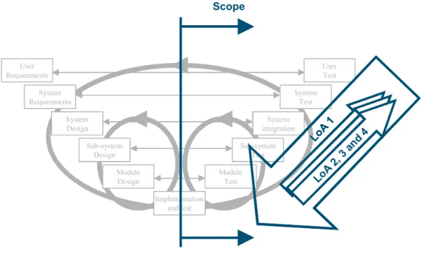
For the lines of attention 2 to 4 a bottom-up approach is taken; see Figure 4.2. These start at the implementation/design level, dealing with modules and components and move at a later stage to the design/requirements level and the subsystem and system level. The actual examples of components, modules, etc. used are synchronized such that the modeling results can be compared across these 3
System Integration System engineering =
System Specification
Mechanics Electronics Software
time
Testable component
Testable component Test strategy
Test generation, Automation, Test regression Coupling test and
Simulation environment
Diagnosis
System Integration System engineering =
System Specification
Mechanics Electronics Software
time
Testable component
Testable component
System Integration System engineering =
System Specification
Mechanics Electronics Software
time
Testable component
Testable component Test strategy
Test generation, Automation, Test regression Coupling test and
Simulation environment
Diagnosis
different lines of attention. The first line of attention takes a top-down approach. This line of attention also takes care of the integral aspects of the other 3 lines of attention.
Figure 4.2. Focus areas of the Lines of Attention, depicted in the v-diagram.
4.3. Intended results
4.3.1. Background knowledge
The background knowledge of each project partner is described in the technical annex of the project co-operation agreement.
4.3.2. Global description of foreground knowledge
The foreground knowledge of the project participants is described in the technical annex of the project co-operation agreement.
System Requirements
System Design
Sub-system Design
Module Design
Implementation and test
Module Test
Sub-system Test
System integration
System Test
User Test User
Requirements
LoA 1
LoA 2, 3 an d 4 Scope
System Requirements
System Design
Sub-system Design
Module Design
Implementation and test
Module Test
Sub-system Test
System integration
System Test
User Test User
Requirements
LoA 1
LoA 2, 3 an d 4 Scope
5. PROJECT EXECUTION
5.1. Overall plan with major milestones and decision moments Phases and reviews
The master planning contains several phases, with major review milestones in between and a closing review at the end. The major review meetings have the purpose of discussing the status of the project, including the achievements obtained and budget spent. Further, insight is given in next phases, budgets required, and end-date of the project. In particular, this meeting decides and agrees unanimously upon an update of the technical annex of the co-operation agreement. This updated version of the technical annex specifies the ownership and usage of the project results of the next project phase.
Increments
Three consecutive increments are performed, each closed with a review. Each increment has the phases of research per Line of Attention, integration of the results of all Lines of Attention with applying the results on an ASML case; and consolidation of all the results for further use. During the integration and consolidation phases, also the detailed definition of the following increment is provided and the content of the technical annex is updated (and decided upon during the review). In the current version of the project plan, the increments are detailed as far as possible. It is anticipated that, due to the complex nature of this project, the detailed definition of the increments needs a regular update.
Coupling to ASML development projects
The ASML industrial application cases are taken from either an existing product, and in the course of the project, also from actual development projects. In this manner, it is ensured that the project is fed with real-life complex industrial examples. It also provides a possibility for early knowledge transfer from the project to ASML and other interested parties.
Per Line of Attention, the activities are described in the following.
5.2. Activities within and over the Lines of Attention 5.2.1. Line of Attention 1: Test Strategy
Contribution: ASML TU/e, Mechanical Engineering Embedded Systems Institute Problem statement
Product reliability at first shipment is a critical success factor for ASML.
In the current integration and test strategy the main test problems occur when the various disciplines integrate their results into the final system. Integration is in practice not always driven by the functional dependencies and the risks that changes are supposed to carry with them. Very often development resources, delivery schedules, a pre-defined timetable of machine and/or SW integration/test slots, and a number of other constraints determine the integration and test order.
Objectives
1) Develop an integral multidisciplinary test strategy such that:
Testable system equals sum of testable subsystems, etc.
Components can be tested and diagnosed in subsystem environment.
Minimum granularity of testable component equals replace spare parts
Subsystems can be early tested in isolation and in joined system and simulation context, the same subsystem can be tested in its environment.
2) Allow for and define a growth path from current system architecture to a testable system architecture
3) Trade-off analysis for testability requirements (e.g. on cost and performance) based on risk analysis.
Approach
The approach is mainly model-based and (real-life) case-based; this is also true for all other Lines of Attention. The basic testability approach taken for this project is based on the notion that a system is subdivided in components and that components are integrated into systems via multiple levels of aggregation, e.g. component, module, sub-system and system. This subdivision and integration is treated as a view on the system architecture. Components are tested stand-alone and as integrated set of components. ASML examples are taken at each level of the system architecture.
To test components in an integrated set-up, it could mean that additional observability and controllability requirements have to be taken into account. These requirements should take profit of all available, and possibly new, approaches. For example, subsystems can be tested via boundary scan techniques, coupled to software test techniques. While progressing along this route, gradually the modeling of the system in components is replaced by a mixture of modeled (not yet available) and real life components.
We strive for generic results, suitable for application in similar systems such as printers, medical equipment, aeronautics, etc.
Activities
Initial phase: study and comparison
This Line of Attention starts with an investigation of the current ASML test and integration practices. Practices are compared with cases found in literature and via discussions with similar industry partners. Experiences are obtained by actively participating in ASML test activities.
Deliverables:
Report on current practices compared with international state of the art.
Requirements for other LoAs in terms of conditions for use and synchronization between the various LoAs.
Increment 1: strategy development on system level and testable requirements
Criteria are being defined for the choice of test methodology for the system and the subsystems.
Criteria are defined on how to create on integration plan and how to manage integration plans. In this manner, the choice for test methodology is backed with data.
The increment is concluded by a case on ASML system level.
Deliverables:
Test strategy and test process definition.
Consequences from test strategy choice for other LoAs.
Case study report
Increment 2: strategy development on subsystem level and testability requirements
Criteria are being defined for the choice of test methodology for the subsystems, modules, and components.
Decomposition of a system as a test view on system architecture
Trade-off analysis of testability requirements (e.g. when/where/how/why to place test points such as sensors, actuators, additional component interfaces, etc.).
Take results from other LoAs as entry for decomposition and trade-off analysis
The increment is concluded by a case on ASML subsystem – system level, this is done in close cooperation with the other LoAs.
Deliverables:
Decomposition rules for test purposes.
Trade-off analysis methods and tools
Case study report.
Increment 3: consequences on system architecture and integral test strategy
Determine consequences and requirements for testable system architecture.
Obtain integral view over all LoAs.
Deliverables:
Definition of the total picture.
Route towards introduction (change process).
Final phase
Definition of how to put all results in place in a product organization such as ASML. A close relation exists between test/integration methodology and existing ASML working methods.
Changes in test methodology should fit the ASML working methods, but where applicable` barriers in the existing working methods can be investigated and proposals to change these can be made.
Deliverables:
Conclusions and recommendations.
Proposals for further investigation.
.
5.2.2. Line of Attention 2: coupling simulation and test environment
Contribution: ASML NLR TUD TNO TPD Problem statement:
1. In current practice testing is mainly performed after completion of the product development and prior to shipment. This implies that testing directly influences the shipment date.
2. To test multi-disciplinary components (e.g. combining software with electronics, mechanics or optics), all components need to be available. For some (mechanical or optical) components this results in a significant investment to have the actual components available.
3. When time-to-market concerns limit the amount of testing time, the rigor of testing is reduced.
Consequently, the risk increases that certain malfunctions are not found prior to shipment. The resulting reduction in availability directly impacts market share.
Given the above (three fold) problem statement, this results into the following observations:
Component dependencies (software, hardware) and availability of those components directly limited the test scheduling. This directly determines the time to market and predictability of shipment date.
Components abstracting hardware cannot be tested without the actual underlying hardware. This directly results in the need to use expensive resources up to complete production quality systems.
Currently, testing is mainly manual and the implementation, documentation, and evaluation of test procedures influences the product quality. The Time to market pressure dictates the amount and rigor (coverage) of tests.
Objective
To address the above problems, the usage of modeling and simulation techniques will be investigated in this Line of Attention. With this approach:
Testing can be started before all components are completed (problem #1),
Testing of combined multi-disciplinary components can be done with simulated hardware components (problem #2), and
Testing can be made concurrent with system development, allowing an increase in the total testing rigor (problem #3).
It will be investigated how these modeling and simulation techniques can be integrated in the ASMl test and verification methodology. In case, the simulation models do not reflect the reality correctly (anymore), the models should be easily maintainable.
Therefore, the main objective is the conception of an integrated simulation and test environment that has the following features
Support for real implementations (software, hardware) as well as (existing) simulation models.
Support for component integration..
Support for batch mode testing (e.g. for regression testing).
Support for automated test execution and pass/fail verdict.
Support for (remote) model based diagnostics, using same interfacing for models and real implementations.
Support for hybrid (discrete event, continuous time) models.
Support for real-time and simulation time execution.
Approach
The approach taken is to extend the capabilities of the existing test infrastructure in a number of consecutive steps.
Start with a mono disciplinary software environment to test a single component and its environment.
The next step is a mono disciplinary software environment, with multiple components and their environment.
The third step is a single multi-disciplinary component.
The final step is a multiple disciplinary component consisting of multiple sub-components.
Activities Initial phase:
Investigate the current state of the art within ASML with respect to existing models, test infrastructure, tooling, and roadmaps. This is done by reading the appropriate documentation, interviewing the proper ASML persons, and studying the operation of the subsystems of the ASMl machines.
Compare this investigated ASML practice with state of the art in other organizations such as Philips Medical Systems, Océ, and ESA.
Construct a test infrastructure roadmap. The Roadmap is a result of the activities of this phase and combined with the dependencies with the other line of attentions.
Deliverables:
Overview of current simulation models
Overview of different architectural view (disciplines: software, electronics, optics, mechanics)
Overview of test practices and test tooling
Roadmap for “test and simulation environment”
Selection of suitable case to be used in following phases.
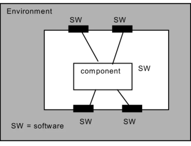
Increment 1: Mono disciplinary (=software), single component.
Figure 5.1. Mono disciplinary, single component.
Design and provide a prototype implementation of a mono disciplinary, single software component test infrastructure that allows simulation or real execution of both the component and its environment; see Figure 5.1.
Deliverables
:
Extensions of interface descriptions (amongst others as provided by LOA 3).
Environment
com ponento m p
SW SW
SW SW
SW
SW = software
SW Environment
com ponento m p
SW SW
SW SW
SW
SW = software
SW
Interfacing mechanism for real/simulated component/environment.
Environment simulator
Component simulator
User manual
Evaluation of this phase Dependencies with other LOAs:
Structured test vector input and structured result output with LOA 3.
The restrictions of this deliverable are the following:
1. Discrete event 2. Real-time
3. Single component 4. Software only
Increment 2a: Mono disciplinary (=software), multiple components.
Figure 5.2. Mono disciplinary, multiple components
Design and provide a prototype implementation of a mono disciplinary, multiple software components test infrastructure that allows simulation or real execution of both the components and its environment; see Figure 5.2.
Deliverables:
Extended interfacing mechanism for multiple real/simulated components within their environment.
Updated components simulator.
Updated user manual
Evaluation of this phase
The restrictions of this deliverable are the following 1. Discrete event
2. Real-time
3.
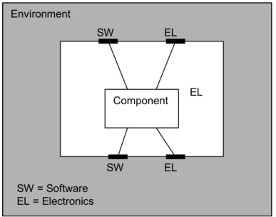
Software onlyIncrement 2b: Multi disciplinary, single component.
Environment
SW SW
SW SW
Component
Component SW
SW Environment
SW SW
SW SW
Component
Component SW
SW
Figure 5.3: Multi disciplinary, single component.
Design and provide a prototype implementation of a multi disciplinary, single software component test infrastructure that allows simulation or real execution of both the component and its environment; see Figure 53.
Deliverables:
Extensions of interface descriptions (amongst others as provided by LOA 3).
Extension of the interfacing mechanism for real/simulated component/environment.
Extension of the environment simulator
Extension of the component simulator
Updated user manual
Evaluation of this phase
The restrictions of this deliverable are the following 1. Real-time
2. Single component
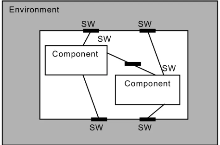
Increment 3: Multiple disciplinary, multiple components.
Figure 5.4. Multi disciplinary, multi component.
Environment
SW EL
SW EL
EL
SW = Software EL = Electronics
Component EL Environment
SW EL
SW EL
EL
SW = Software EL = Electronics
Component EL
Environment
SW SW
SW EL
Component
Component EL
EL Environment
SW SW
SW EL
Component
Component EL
EL
Design and provide a prototype implementation of a multi disciplinary, multi software component test infrastructure that allows simulation or real execution of both the components and their environment; .see Figure 5.4.
Deliverables:
Interfacing mechanism for real/simulated component/environment.
Updated environment simulator
Updated component simulator
Updated user manual
Evaluation of this phase Dependencies with other LOAs:
1. Structured test vector input and structured result output with LOA 3.
The restrictions of this deliverable are the following 1. Real-time
2.
Multi-component and interdisciplinary.Final phase
Consolidate results of 4 iteration phase results
Address relevance of the obtained results with respect to original ASML problem description
Combine obtained results with the results of the other lines of attention.
Produce the conclusions and recommendations specific for ASML.
Deliverables:
Coupled test and simulation environment based on all results of all LoAs.
Optionally recommend topics for further research
Proposed implementation of the obtained results for ASML (transfer process).
5.2.3. Line of Attention 3: Test generation, automation, and regression testing
Contribution: ASML UT KUN TU/e Mechanical Engineering TU/e Mathematics & Computing Science Problem Statement
Within ASML testing of systems is very important to assess and control their quality. But testing takes many resources, takes much time, it leads to critical delays in the delivery of the product, and after testing it is still difficult to determine to what extent all requirements have been covered. The situation at this moment is that test activities take place mainly at the end of the manufacturing cycle, and are done manually. Since many versions and modifications of systems occur, this in particular applies to regression testing.
Objectives
The objectives of this Line of Attention are the following.
1. Early concurrent testing: testing as integrated activity in parallel with the other development activities, and starting as early as possible in the development cycle;
2. Improving the efficiency and effectiveness of testing through automation, involving test generation, test execution and analysis. In particular, routine kinds of testing and regression testing must be fully automated;
3. Measuring the achieved requirements coverage and system quality.
Approach
The technical approach is to work towards complete test automation based on model-based testing.
Test automation involves all phases of testing, including test generation, test execution in ASML specific environments, and analysis of test results leading to a verdict. Automation is model based, which concerns developing models of the systems under test, as well as testing models of systems.
The latter allows early and parallel testing when the real implementation is not yet available. The same models will be the basis for the measurement of coverage.