Problem Statement
OWL: Object-Oriented Workplace Laboratory
1. Introduction
More than 50 million American workers are based in office buildings. The central goal of the Center for Building Performance and Diagnostics has been to design workplaces that offer healthy, productive environments for these workers, and that are energy effective and environmentally sustainable additions to the built environment.
The Intelligent Workplace (IW), a project that evolved from these goals, will be a
testbed of advanced building products and systems — an internationally unique venue for studying how workplace design can maximize occupant comfort, well being, and productivity.
A current trend in the building industry is to provide distributed services and control for the individual occupant as a strategy to correct the overreliance on large centralized systems that characterize office buildings built in the last 30 years. At the IW workers will have more control over their environmental conditions — adjusting light level and temperature of their workspace, reducing glare, controlling speed and direction of air flow delivered to workspace. (You can do that in your car — why not your office?) An energy-efficient facade will allow for fresh air ventilation from operable windows and incorporate movable shading devices that adjust to minimize glare and maximize natural lighting of the workspace. This facade also balances temperatures within the space: i.e., your desk can be next to a window, but you won’t freeze in winter or bake in summer.
The average churn rate in american offices is 30%., that is, 30%of the occupants will move in the period of one year. Designed for maximum flexibility, the IW will feature a raised floor under which the telecommunications and mechanical systems will be installed. Distributing such building services through the floor will allow for rapid reconfiguration of office space to meet changing organizational needs and changing technologies. A modular design will allow researchers to replace components and even entire systems in order to study newer ones as they become available.
The effectiveness of these innovative components depends on their integration and communication with the rest of the building components. Thus, the integration of the
15-413 Software Engineering Carnegie Mellon University School of Computer Science http://cascade1.se.cs.cmu.edu/
15-413
Handout 2
27 August 1996building control systems with their environment and with the occupants plays a crucial role for the design of an “intelligent” living environment.
It is desirable to adopt three forms of control in the Intelligent Workplace: responsive, scheduled, and user driven. Responsive control is when the system reacts to a change in sensor reading by actuating some components. Scheduled control can be adopted in the presence of predictable data that allows the components to be directly controlled by a carefully designed schedule. For example, since the position of the Sun is predictable, a schedule for the interior shades of the Intelligent Workplace can be adopted. Control system should be flexible enough to respond to the needs of the occupants. If they would like to change the temperature of their local environment, they should be given that opportunity.
In this semester you are asked to build a system called OWL (Object-Oriented Workplace Laboratory) that attempts to improve the way we deal with buildings.
The OWL system is to be used by personnel for building control and maintenance of the Intelligent Workplace. Please visit the Web Page (http://www.arc.cmu.edu/cbpd/
iw.html) for more information about the Intelligent Workplace.
2. Scenarios
In the following we describe several scenarios that the OWL System must be able to deal with. We distinguish between core and optional scenarios and you are asked to develop a prototype that demonstrates the core scenarios based on a system design that is extensible enough to deal with the optional scenarios.
2.1 Building Operation Data Collection (Core)
Sensor data such as outside and inside temperature, CO2 and relative humidity are measured with the help of a data logger and stored in a sensor database. Weather forecast data is retrieved from the Internet and is saved in a weather database. A history of control actions by occupants are logged in a control action history database.
These three types of data (past data, real-time data, weather forecast data) will be used by a future building operation application for system monitoring, real-time and
predictive building control, as well as trend analysis.
2.2 Building Facility Management (Core)
The facility manager or a privileged user, located locally or at a remote site opens the browser of the OWL system and uses speech to open a 3-D view of the Intelligent Workplace and to navigate through the building, browsing through rooms, looking at several items in each room, such as air-conditioners, furniture, computers and
information associated with the room such as occupancy lists or a room schedule.
While navigating through the building the manager selects a hot spot for a PEM (Personal Environment Module). The information associated with the hot spot is displayed on the screen along with system descriptions and annotations.
Two adjacent rooms, formerly normally equipped offices, are merged together to form
a conference room to be used by different groups for their face-to-face meetings.
2.3 Building Control (Core)
A building occupant opens the control screen of a PEM (Personal Environment
Module) and adjusts the temperature and the air speed. The control information is sent to the physcial equipment. The new values along with a time stamp are also stored in a database. The system looks at other PEM readings in the area. If they are varying by a huge margin, it gives a warning to the building occupant and reports this to the facility manager. If all the values are the same and they are in an extreme state (all maximized or minimized), it sends a message to the Facility Manager (next semester to the
Building Intelligence) stating that the current state of the system needs to be altered since the occupants are not satisfied with their environment.
The control of light reflection is most crucial on a sunny day. The purpose of light reflection control systems is to maximize daylight availability while minimizing solar gain and discomfort glare.
The OWL system collects temperature and light sensor data in the Intelligent
Workplace and weather forecast data from the Web. During warm days, OWL uses the light reflection controls to maximize daylight and minimize solar gain. If there is direct sunlight or an overcast sky with bright light that may cause glare on the screen of the workstations, the controls are set to reject this glare and make it a pleasant environment to work for the occupants located in perimeter workstations.
2.4 Building Simulation (Core)
A building designer creates spaces for offices and conferences rooms, walls, and other components (geometric and non-geometric data) for the intelligent workplace using a library of component specifications and a CAD tool. Specifying the location of the rooms with respect to the sun, weather forecast data and the occupancy and usage profile, the building designer then visualizes the temperature profile of all the spaces by calling a simulation program called SEMPER - an active, multi-aspect design and simulation environment currently developed at the Department of Architecture.
SEMPER requires the designer to select the type of simulation to be performed, either multiple parametric simulations on a specific domain, or concurrent simulations on multiple performance domains. The simulation results are graphically displayed on the screen, and archived at the user’s request.
2.5 Building Maintenance & Fault Isolation (Optional)
The Building Control System of the OWL System monitors the behavior of the
Intelligent workplace with the help of two data sources, real-time and archived data to alert the Facility Manager of a malfunction or breakdown of a specific building system component. The fault isolation is done through identifying severe deviation of
performance parameters or unusual trends.
2.5.1 Trend Analysis (Optional)
A Trend Analyzer refers to building operation history data (vector of sensor data, control action, outputs) and identifies system behavior patterns according to the
environmental changes. Identified trends are utilized for both of fault isolation and predictive building control.
2.5.2 Predictive Building Control (Optional)
Weather forecast data and predicted internal loads based on the trend analysis are fed into a Building Simulation Application to instantiate multiple simulation sessions with selected set of system control parameters. The predicted internal loads are comprised of loads consisting of building facility equipment, office equipment and people. Results of the simulations are compared against target performance indices to select the best projected control strategy. The chosen control plan is saved in a database for execution.
3. Preliminary Requirements Analysis
A preliminary analysis of the problem has already been performed which has resulted in an object model of a Site shown in Figure 1. A Site has attributes such as location,
Figure 1. Object Model of a Site with several Buildings
Exterior Element
Construction
#ID
#Name Opening
#ID
#Geometry
Attachment
#ID
#Geometry Space
#Name
#Geometry
#Function
#Volume
Enclosure Element
#Adjacencies
Partition
Space Elements
#Geometry
#Location
People Equipment Light Furniture Building
#Name
#Geometry Site
#bg-noise
#weather
#Geometry
Feature
#name
#Geometry has
contains
surrounded by
is confined by contains
has has
has
made of
made of
geometry, weather condition, background noise etc. It also has additional Features such as trees or a pond. A Site can contain many Buildings. A Building is surrounded by Exterior Elements such as parapets or catwalks. A Building has many Spaces, each of them identified by its geometry, orientation and function. A Space contains various Space Elements which can be either a Partition, People, Equipment, Light, or Furniture. A Space is confined by Enclosure Elements such as a roof or a ceiling. Some Enclosure Elements can have Openings such as Windows, Skylights, Doors and Attachments like Shading Devices, Blinds. A Partition can also have several Attachments. Enclosure Elements, Openings, and Partitions are made of various Constructions with multiple layers and materials.
Please use the scenarios and this object model as the basis of your interviews with the client during the requirements analysis of the OWL System. We expect that the object model will undergo several incremental and iterative changes as a result of the requirements analysis phase.
4. Functional Requirements
The OWL System must
• provide geometric and topological operations available in today’s integrated CAD tool (including 3-D visualization)
• provide building simulation for selected spaces or components
• be able to display simulation results.
• must be able to review and navigate building, data and results remotely from any place that has an Internet connection.
• provide the ability to store, retrieve, update and view building data (e.g. description of building components), building operation data (e.g. sensor data), as well as
reference data (e.g. libraries of glass types, weather data).
• allow the occupant to retrieve information from sensors and control their settings.
5. Global (Nonfunctional) Requirements
• The OWL System must provide a graphic user interface that provides uniform access to the functions offered.
• The OWL System must provide concurrent access by multiple users, accessing the system locally and remotely. Each of the applications can be run independently from each other as a separate process, while still allowing the applications to communicate with each other.
• The software architecture must be extensible to deal with the optional scenarios
• The software architecture must provide a manufacturer independent interface to the building sensors.
• Any new code written as part of this development effort must be platform independent (that is, it must run on platforms such as Windows NT, Sun Solaris and Macintosh).
• Model-based software Engineering techniques has to be used. The application domain must be modeled with OMT. The model of the system must start with the
building model shown in Figure 1. The system design and implementation must be derived from the OMT models developed during the analysis phases.
• Every occupant has access to a portable/ wireless computer. The user interface must take these conditions into account during the development phase.
6. Target Environment
This section describes components of the intelligent workplace already in place or made available for the developers of the OWL System. The Intelligent Workplace is described in Section 6.1. Section 6.2 contains a description of the data loggers for measurements of sensor data. One data logger will be installed in the Software Engineering Lab, the other in the Intelligent Workplace. Eventually, the data loggers will be replaced by commercially available systems, in particular MetaSys from Johnson Control and Instabus EIB from Siemens. These two systems are described in section 6.3. The SEMPER simulation environment is described in Section 6.4.
6.1 Intelligent Workplace
This section describes components of the Intelligent Workplace that are relevant for the development and delivery of the OWL System.
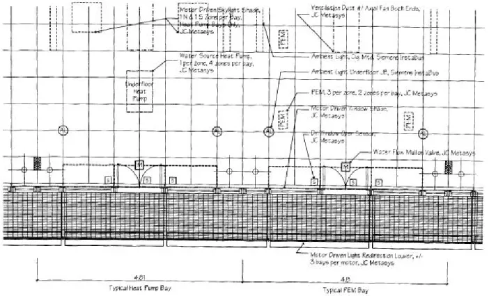
The Intelligent Workplace is a 7000 sq.ft. office environment under construction on the top floor of Margaret Morrison Building. The goals for the project is to provide
occupant satisfaction, organizational flexibility, technological adaptability, and energy and environment effectiveness. The picture below presents the typical lay out of the
interior systems. There are two entrance points to the IW. One of them is from the south end which is shown on the right side of Figure 2. The south end can be entered through the fourth floor of the Department of Architecture. A stairwell in the third floor leads to the north zone (right side of Figure 2). The Center for Building
Performance and Diagnostics will be located on the north zones (left hand side of Figure 2. Layout of the Intelligent Workplace
picture). It will be occupied by the faculty, researchers and other staff members. In the north zones, the air is delivered from fourteen one-ton heat pumps into a combination of closed and open work areas. The south zones will be occupied by the graduate students and outside researchers. In this area, the air is delivered from the Personal Environment Modules (PEM), integrated with the desk of each workstation. PEMs provide the occupants the local control of air speed, air direction, temperature, and lighting. Along the perimeter of the IW, each (4.8 ft.) 1.2 m. is called a bay. There are 3 workstations per bay in the south zones and 2 per bay in the north zones. The raised floor is adopted throughout the IW. The entire duct system and the cabling is done under the floor.
Figure 3 shows the floor plan of the Intelligent Workplace. Several acronyms are used in the figure. “S” stands for a door, a window, or a sensor. “M” stands for the valve of the water mullions in each bay. “PEM” is the Personal Environment Module that provides air for and control over the occupants workstation. “AL” stands for floor mounted indirect ambient lights. The dashed line indicates that the component <<Sila:
Which component?>> is either under the floor or above the ceiling.
Figure 2 shows a section view of the Intelligent Workplace with the electrical and mechanical systems.
Figure 3. Floor Plan of the Intelligent Workplace
The electrical system contains direct and indirect light fixtures, ballast, mechanized window shades for the windows and skylights, photovoltaic powered ventilation fans, mechanized light redirection louvers and perimeter indirect luminaire. The artificial light sources include floor mounted perimeter indirect luminaires and ceiling mounted direct/indirect luminaires with two fluorescent lamps and a dimmable ballast for each luminaire. The skylight and interior shades as well as light redirection louvers are utilized to optimize daylight availability in the Intelligent Workplace.
The mechanical system include the Johnson Controls Personal Environment Module (JC PEM), the heat pump, water flow mullions as well as supply and return ducts. The JC PEM is connected to the hard supply duct via flexible duct and is mounted on each desk in the south zones of the Intelligent Workplace provides the local air and controls for the occupants in that part of the building. In the north zones, the heat pumps provide the local conditioning. The water mullions provide radiant heat and cooling and are located close to the facade to counter effect the radiant heat and cold from the windows.
6.1.1 Personal Environment Module (PEM)
PEMs are integrated environment control systems designed for open-plan Figure 4.
workstations. These systems are located in each workstation at the south zones of the Intelligent Workplace. They are integrated with the furniture system as well as the central air distribution system so that they can provide satisfying and comfortable working environment through individual control of temperature, airflow, radiant heat, sound masking, and task lighting. The benefits of using this system include improved thermal comfort, indoor air quality, visual comfort, concentration, productivity, energy efficiency, flexibility, and reduced churn costs. Also, this system has a networking capability to the Johnson Control Metasys facility management system.
6.1.2 Light Redirection Louver (LRL)
There are eight sets of light redirection louvers located around the perimeter of the IW.
These devices are glass louvers which have high reflectance (mirror-like) on one side.
They are used to eliminate glare for the perimeter workstations and redirect the
daylight inside the building. Each set of louvers is actuated by a voltage driven motor.
The goal of the control strategy should be maximizing daylight availability while minimizing solar gain and discomfort glare due to direct sun light. When the system is in heating mode, LRLs should admit sunlight and the control system should make sure that perimeter workstations do not have glare. When the system is in the cooling mode, depending on where the sun is located in the sky, those LRL on that side of the building should reject sun light (thus rejecting solar gain which is a burden on cooling loads) while all others are in admitting positions. When the system is in ventilation mode, as long as the inside temperatures are comfortable, sun light should be admitted into the building. As soon as the temperature goes above a set point, the systems should act as if it is in cooling mode.
6.2 Data Loggers
The MicroDataLogger is a portable, battery powered, 4-channel data logger capable of recording time-series information from a wide variety of sensors and electrical
transducers. Sensors include temperature, CO2 and relative humidity.
A PC is used to configure the MicroDataLogger for a particular measurement and to retrieve and analyze the recorded data. In general, once the MicroDataLogger has been configured, it is left alone in the room, measuring sensor data for a period of up to 24 hours. The MicroDataLogger has four plug-in slots for sensor and signal conditioning modules. When a module is connected to the logger, the Auto ID feature identifies the module’s function, and will automatically program the correct excitation power and sensor warm-up time. The MicroDataLogger’s non-volatile FLASH memory can store approximately 64,000 readings total, or 16,000 for each of four channels. The frequency of MicroDataLogger measurement is user-defined and can vary from one measurement every three seconds to one every hour. To conserve the MicroDataLogger’s memory, a number of individual measurements can be averaged together and stored as one reading. Other features include a LCD, real time clock, 12 bit resolution, precision voltage reference, serial port, and easy-to-use Windows-based logger control software.
6.3 Siemens Instabus and Johnson Control Metasys
There are two commercially available systems that will be installed at the IW; Siemens Instabus EIB and Johnson Controls Metasys. Instabus will be used to control the
electrical systems while JC Metasys will be used to control primarily the Heating Ventilation and Air-conditioning Control (HVAC) system. Beyond the capacities of these two systems, it is desirable to have the collected data from the building to be organized in a database management system. The organized data should be presented in a manner in which it can guide the facilities manager and the occupants so that they can make educated decisions about their environment. In addition, a person sitting in a remote location should be able to access this data, and if necessary alter it.
6.4 SEMPER
SEMPER provides building performance simulation modules for energy, thermal comfort, HVAC, air flow, acoustics, eco-balance, and lighting. These simulation modules are dynamically linked with a CAD system. SEMPER thereby allows a designer to input a building using the CAD system, and “seamlessly” conduct performance analysis. For example, SEMPER creates the appropriate computational representations for the simulation modules and carries out the simulation without any additional user intervention.
SEMPER is a system currently being developed at the Department of Architecture. A proof-of-concept version of SEMPER has been implemented, which incorporates the energy and thermal comfort simulation modules. Central to SEMPER’s design is an object model shared by applications such as a Space Attributes Editor, a Wall Attributes Editor and more generic Graphic Editors.
The object model is implemented in an object modeling language called OML. OML provides language bindings between the objects and the application-specific data structures. The primary interface is written in Tk/Tcl, while AutoCAD has been used for geometry input/display.
Prototype version of the HVAC, air flow, acoustics, and eco-balance modules have
Graphic Editor Space Attributes
Editor
Wall Attributes
Editor ....
USER INTERFACE
OBJECT MODEL
Create, Modify, Delete Objects
Display Object Characteristics
Automatic Bindings Between Application Data Structures and Corresponding Objects Object-level Linkages
APPLICATION APPLICATION
a b
already been developed, but have not yet been linked to the SEMPER environment. All the performance simulation modules are written in either C or C++.
7. Design Issues
A system dealing with the scenarios described in the previous sections will be complex and will require a multi-team effort. We have decomposed the system into a software architecture shown in Figure 1.
• -Still needed. Refine top level design to show software architecture based on CORBA as software bus connecting applications, browsers, sensors and databases.
8. Development Environment
The development of the OWL System makes use of the facilities offered in the clusters on CMU Campus as well as the Software Engineering Laboratory located at Building D, Room 154A. While the clusters are shared with other students taking other courses, the resources at the vehicle lab are to be used solely for the development of the
OWLOWL System. The Software Engineering Laboratory offers a set of 10 PCs running Windows’95 or Windows NT, 10 Macintosh running MacOS 7.5.3 and 10 HP
workstations running Andrews. These machines are connected via a local Ethernet. The Intelligent Workplace operates a local area network (LAN) consisting of a set of PCs, Macintosh and Unix Workstation connected by Ethernet.
Figure 5. Top Level System Design of OWL User Interface
Visualization
Control
Facility Management
Simulation
Database
9. Teams
The following teams are assigned to work on the subsystems. You must be a member of one of the core teams. You may also decide to be a member of the cross-functional teams (which is optional)
9.1 Core Teams
9.1.1 UI Team (TA: Prithvi Rao)
• Develop GUI
• Visualization
• Provide speech interface to Web Browser
• Integrate the various subystems in an integrated Web Browser
• Develop several rapid prototypes of the UI 9.1.2 Visualization Team (TA: Brian Cavalier)
• Navigation through a 3-D model of the building (Java application)
• Definition of selectable hot spots
• Create Links to Databases such as the sensor database
• Navigation of selected building operation data on the Web environment in hyper- media form
• Compute and visualize the energy consumption of the building in real time 9.2 Simulation Team (TA: Shawn Hurley)
• Interface to SEMPER
• Design and implement a client/server architecture for running the simulations For more information read Mahdavi, A. “A New Computational Environment for Simulation-based Building Design Assistance”, Proceedings, 1996 International Symposium of CIB W67, E. Panzhauser (ed.), Technical University of Vienna, Vienna, Austria. pp. 467-472. This article is posted as a PDF file in the simulation team home page (found via the 15-413 home page).
9.2.1 Facility Management Team (8, TA: Shawn Hurley)
• Maintain list of IP numbers for each of the room
• Cable Management (Schematic of cabling structure, network points, hubs
• Create or reuse building editor
• Map of Furniture
• Some rooms have calendars associated with them
• Allow for quick updates when a member moves from one office to another
• Scenarios: 2 rooms are joined into one, one room is split into 2 offices, one room is relabeled from an office to a conference room (Needs a calendar for scheduling meeting times).
9.2.2 Control Team (8, TA: Sam Perman)
• Provide real time display of sensor data in graphical form)
• Control PEM
• Airhandler control
• Proprietary building control implementation(computational algorithm + control signaling)
• Allow the user to control a PEM
• Provide visualization of the functions of a PEM
• Interface to sensor database
• Interface to Light Redirection Louvers
• Allow the user to control the Light Direction 9.2.3 Database Team (8, TA: Elizabeth Bigelow)
• Use an Object-oriented database
• Define Sensor Database format
• Provide archival of building operation data(sensor data, control action data, and control output data)on database
• Log data from data logger and store
• Capture weather forecast data from Internet and store it in database 9.3 Crossfunctional Teams
9.3.1 Architecture
The responsibility of this team is to model the OWL System as a set of services provided by each of the subsystem.
9.3.2 Integration
The responsibility of this team is to provide a plan for Integration Testing and System Testing. The Integration team is also responsible for the delivery of the full OWL system.
9.3.3 Documentation
The documentation team handles the documents produced by the project. The
documents are published on the Web during the duration of the project. At the end of the semester all the documents will be copied onto a CD-ROM.
10. People Contacts
The client for the project is Prof. Volker Hartkopf, professor in the Department of Archi- tecture. Consultants for some of the subsystems and tools are also available. The consult- ants are:
• Control subsystem: Steve Lee and Sila Berkol.
• Simulation subsystem: Ardeshir Mahdavi, Seongju, Robert Ries and Paul Mathew.
• Facility Management subsystem: Karsten Menzel.
• CASE tool: Mark Pollard
• Java: Andrew Houghton
The manager for the software engineering laboratory in BOM 154 is Joyce Johnstone.
11. Client Acceptance Test
This is a broad problem statement, and as such, all the functionality that has been alluded to is not expected to be delivered in one semester. The object model for Building shown in figure module is tentative and will certainly undergo several
iterations during your development effort. The client is very willing to discuss any and all recommendations on changing the requirements specified in this document. During the requirements analysis phase of the project, the functional and global requirements of an acceptable prototype will be established. An initial prototype of the OWL system is expected six weeks after the functional requirements have been established. The delivery of the second prototype of the OWL system is expected at the end of the semester.The client realizes that all components of OWL may not be functional by the end of the semester; however, the functional units of the prototype that are delivered at the end of the semester must work in the environment of the intelligent workplace.
Users of the OWL system include all occupants and facilities management.