Inverse spin Hall effect in metallic heterostructures
Dissertation zur Erlangung des Doktorgrades der Naturwissenschaften (Dr. rer. nat.) der Fakultät für Physik
der Universität Regensburg
vorgelegt von Martin Obstbaum aus
Laupheim
im Jahr 2015
Prüfungsausschuss: Vorsitzender:
1. Gutachter:
2. Gutachter:
weiterer Prüfer:
Prof. Dr. Jaroslav Fabian Prof. Dr. Christian H. Back Prof. Dr. Dieter Weiss Prof. Dr. Christian Schüller Termin Promotionskolloquium: 17.12.2015
Dedication:
To Eli and my parents
Contents
1 Introduction 7
2 Spin Hall effects 13
2.1 Mechanisms of spin dependent scattering . . . 14
2.2 Phenomenology of SHE and ISHE . . . 17
2.2.1 Charge and spin currents . . . 17
2.2.2 SHE and ISHE . . . 19
2.2.3 Experimental approach to SHE and ISHE . . . 20
3 Ferromagnetic resonance and spin pumping 27 3.1 Magnetic moments and magnetization . . . 28
3.2 Micromagnetism and thin ferromagnetic films . . . 31
3.3 Ferromagnetic resonance . . . 34
3.4 Spin pumping . . . 40
3.5 Line shapes and relative amplitudes of dc and ac spin currents from spin pumping . . . 49
4 Experimental setup and measurable voltage signals 53 4.1 Details about coplanar waveguides and sample design . . . 55
4.1.1 Calculation of magnetic excitation field amplitudes . . . 57
4.1.2 Integration of ferromagnetic / normal metal bilayers into copla- nar waveguide structures . . . 60
4.2 Voltage signals due to inverse spin Hall effect . . . 62
4.3 Voltage signals due to anisotropic magnetoresistance AMR . . . 68
4.4 Voltage signals due to electromagnetic induction . . . 72
5 Experimental results concerning ferromagnetic resonance and spin pump- ing 75 5.1 Non-micro-structured NiFe thin films and NiFe/NM bilayers . . . 75
5.2 Micro-structured NiFe/Pt bilayers . . . 81
6 Study of dc-voltages due to AMR and ISHE 85 6.1 Angle dependent measurements of voltage signals at FMR for in-plane excitation with a CPW . . . 85
6.2 Angle dependent measurements of voltage signals at FMR for out-of- plane excitation with a CPW . . . 87
7 Experimental results concerning the dc inverse spin Hall effect for NiFe/Pt
and NiFe/Au bilayers 95
7.1 Characterization of voltages due to SP-ISHE . . . 95 7.2 Quantifying spin Hall angles for Pt and Au . . . 100 7.3 Temperature dependence of the spin diffusion length for Pt from the
spin Hall angle . . . 106 8 Experimental results concerning SP-ISHE in NiFe/AuxPt1−x bilayers 109 8.1 Fabrication and characterization of NiFe/AuxPt1−x bilayers . . . 110 8.2 Voltage due to ISHE and normalization with respect to AuxPt1−x
dependent parameters . . . 112 8.3 Experimental results concerning the spin diffusion length and spin
Hall angles . . . 117 9 Experimental detection of the ac-inverse spin Hall effect 121 9.1 Experimental setup - measuring ac-voltages in the GHz-regime . . . . 122 9.2 Line shape of voltage signals due to ac-ISHE . . . 125 9.3 Angular and power dependence of voltage signals . . . 127 9.4 Estimation of parasitic effects when measuring voltages due to ac-ISHE129 9.5 Comparison of amplitudes of ac- and dc-ISHE . . . 131
10 Summary and conclusions 133
Bibliography 152
Acknowledgment 153
1 Introduction
Spintronics is a neologism describing the scientific and technological discipline of utilizing the spin degree of freedom in electronic circuitry. This endeavor might be rephrased as the “ever-evolving field of magnetic electronics” [1] at whose heart is the wish to effectively control and manipulate magnetization in terms of data storage.
The great objective is a universal memory which offers high information densities, non-volatility, fast reading and writing cycles and low power consumption [1–3].
Magnetic multilayers, viz. metallic heterostructures have been the main building block ever since [2]. Based on the fact that there is an inequivalence of spin-up and spin-down electrons at the Fermi surface in a ferromagnetic material [4–6] the experimental findings of the charge-spin-coupling at ferromagnetic/normal metal (FM/NM) interfaces [7] and the giant magnetoresistance (GMR) in FM/NM/FM trilayers [8, 9] have emerged. Together with the seminal work in the field of spin diffusion in NM [10, 11] these findings have led to the technological development of the so-called spin valve [12, 13] which allows for effective electrical read-out of the magnetization configuration utilizing the GMR in a FM/NM/FM trilayer. Note that nowadays it is state of the art to use magnetic tunnel junctions (MTJ) where the NM layer is replaced by an insulator which enormously enhances the magne- toresistance [14–19].
Until recently one of the great problems has been the writing process, since it in- volved the need for magnetic fields [2]. The downscaling towards nanomagnets requires ever-greater magnetic anisotropies to sustain a defined magnetization di- rection [1]. In order to switch the magnetization, very high magnetic field pulses and therefore very intense current pulses are required. In terms of heat generation and power consumption this constitutes a vicious cycle. To this end, the direct transfer of spin angular momentum via spin-polarized currents which is enshrined in the theoretical concept of spin transfer torque (STT) [20–26] provides an alternative for the reorientation of a magnetization. Within the last ten years it has led to new possibly revolutionizing data storage concepts such as the race-track memory [27]
which relies on the manipulation of domain walls via STT. In the past five years the topic has gained ever-more momentum when magnetization switching under the influence of STT from pure spin currents [28, 29] or induced by spin-orbit-fields [29–31] has experimentally been observed in FM/NM bilayers. These two effects can complement each other which further enhances the efficiency concerning mag- netization switching [29]. Note that the idea of manipulating the magnetization by injecting pure spin currents has been characterized as “futuristic” [2, 32] not even ten years ago. Now it is already scientific state of the art and we are on the verge of technological applications using STT in magnetic random access memories [33].
In the experiments described in [28, 29, 33] the pure spin currents have been gener- ated by the spin Hall effect (SHE) which converts a charge current into a transverse spin current [34]. In semiconductors and normal metals SHE emerges from the spin dependent scattering of electrons due to spin-orbit-coupling [35]. In a thorough the- oretical work on the “spin Hall effect in the presence of spin diffusion” [36] it has been predicted to find spin accumulation of opposite polarization, which decreases on the scale of the spin diffusion length, on either side of a conductor slab. This led to the first experimental evidence of SHE in gallium arsenide (GaAs) semiconductor systems by optical means [37, 38]. The inverse spin Hall effect (ISHE) has been proposed and theoretically studied based on reciprocity arguments [34, 39]. ISHE summarizes the fact that a pure spin current is transformed into a transverse charge current due to spin-orbit coupling. Note that this bears the intriguing aspect of measuring and quantifying a spin current using standard charge based electronics [40]. To this end the so-called spin Hall angle αSH is defined. Concerning ISHE it is the injected spin current divided by the generated charge current. Apart from understanding the types and origins of spin dependent scattering, the quest for ma- terial compounds which feature large spin Hall angles is one of the main triggers of studying ISHE.
In 2002 Tserkovnyak et al proposed that a precessing magnetization injects a pure spin current across FM/NM interfaces [41–43]. This so called spin pumping can be experimentally evidenced in ferromagnetic resonance (FMR) experiments [44–46].
Due to ISHE a spin current injected from spin pumping can be probed as a voltage signal and this constitutes a powerful experimental framework for quantifying spin Hall angles [47–53]. However, the published values for the spin Hall angles are still not fully in agreement considering the large number of experimental studies. The problem is twofold. On the one hand there is a large set of experimental parameters to be controlled for a reliable quantification ofαSH, for a discussion see [54]. On the other hand one has to be very careful as voltage signals due to ISHE can easily be confused with signals that stem from other origins. This is even more so setting up a spin pumping experiment, since one places the FM/NM bilayers in a microwave field. Under these circumstances the so-called spin rectification effect [55–59] which originates in anisotropic magnetoresistance (AMR) in FM and electromagnetic in- duction in the measurement circuit [60–62] are to be considered. A very interesting aspect of a spin current injected via spin pumping is the fact that it consists of both a time constant (dc) and an oscillating (ac) polarization component. This theoretically expected large ac-component [63] could recently be experimentally ob- served via the so-called ac-ISHE in a NiFe/Pt bilayer [62, 64]. This new field of ac-spintronics which encompasses spin currents in the GHz-regime has just emerged and it will be very interesting to see the future developments.
In this PhD-thesis one of the main aspects is the implementation of an experimental method to reliably quantify the ISHE from spin pumping in metal heterostructures [53]. This includes a thorough study of anisotropic magnetoresistance (AMR) in the presence of magnetization dynamics for a NiFe single layer, as well as NiFe/Pt, NiFe/Au and NiFe/Ta bilayers. Determination of the spin diffusion length for Pt
from thickness and temperature dependence of ISHE will be presented. Furthermore, towards the study of dynamic aspects of injected spin currents into NM [53, 64], the alternating current (ac) nature of the inverse spin Hall effect has been observed and uniquely confirmed for NiFe/Pt. In order to present a clear and comprehensive study on ISHE in metal heterostructures in the context of an experimental setup utilizing coplanar waveguide (CPW) structures for microwave purposes the thesis is organized as follows:
In Chapter 2 the underlying physical principles of spin Hall effects are in the focus.
Its similarity to the anomalous Hall effect especially from a theoretical point of view shall be emphasized and the different nature and mechanisms of spin relaxation in conductors are presented. Then the nature of charge and spin currents and their phenomenological transformation into each other will be explained. This shall be the starting point for the subsequent explanation of the seminal experimental ideas and proofs of concept by Hirsch [34], Zhang [65], Valenzuela and Tinkham [40], Saitoh [47] and Ando et al. [66] in terms of observation and quantification of SHE and ISHE.
Chapter 3 starts with an explanation of magnetic moments and magnetization from both semi classical and quantum mechanical view points. Then the micromagnetic properties of ferromagnetic thin films are described. This is subsequently used as the basis for a theoretical description of FMR in ferromagnetic thin films and the spin pumping mechanism in ferromagnetic/ normal metal bilayers. Special emphasis is laid on the characterization of the magnetization dynamics and spin currents by deriving line shapes as a function of external magnetic field.
In Chapter 4 the extension of FMR principles and spin pumping towards the gen- eration of voltages due to ISHE, AMR and electromagnetic induction are depicted.
The first step is the introduction of the typical coplanar waveguide (CPW) struc- ture which is used to excite magnetization dynamics by the generation of microwave magnetic fields. In order to determine the amplitude of the magnetic driving fields electromagnetic simulations are conducted using the specialized software provided by SONNET. Furthermore, the sample preparation and the used geometries of so-called in-plane and out-of-plane excitation are presented. Accounting for the geometrical subtleties, finally the characterization of voltage lines shapes which are produced by ISHE, AMR and electromagnetic induction as a function of external field takes place. It is the main objective to derive general expressions of voltage line shapes which can be applied to a broad spectrum of experimental configurations as well as material sets and which allows for quantification of physical parameters.
Chapter 5 marks the beginning of the presentation of experimental results. It is centered on FMR and spin pumping in NiFe/NM extended bilayer films as well as micro-structured samples. An explicit comparison of experimental results shall il- lustrate the similarity of microwave absorption (FMR) and voltage spectra in terms of extracting magnetic properties and spin pumping parameters. It furthermore provides results on the limits when transferring theoretical concepts from extended to micro-structured thin films.
Chapter 6 contains a general study of dc-voltages at ferromagnetic resonance. To
this end external field angle dependent measurements will provide insight into the origin of signals - AMR and ISHE. The symmetries of generated voltage signals are compared to the theoretical considerations given in chapter 4. Physical parameters are extracted using corresponding fits to angular dependencies for several NiFe/NM bilayer wires as well as for a single NiFe wire. Especially aspects of electromagnetic coupling between CPW and integrated NiFe/NM wires shall be discussed. It is one of the main objectives to show that it is possible to unambiguously study ISHE in NiFe/Pt and NiFe/Au bilayers with the spin pumping ISHE (SP-ISHE) method.
In Chapter 7 the study of SP-ISHE for NiFe/Pt and NiFe/Au will be elaborated to- wards the quantification of spin Hall anglesαSH. At first an explicit characterization of SP-ISHE with respect to its frequency dependence will be given. Furthermore, temperature dependent measurements of voltage signals at FMR and an unambigu- ous classification of both signals due to ISHE and AMR will be presented. Including an estimation of the spin diffusion length for Pt from a Pt-layer thickness depen- dence the spin Hall angle for Pt and Au shall be calculated from measured voltage amplitudes at FMR. Due to the significance of parameters entering the formula for αSHa detailed discussion will take place. FinallyαSHwill be plotted as a function of the most critical parameters. Furthermore, the temperature dependence of voltage signals due to ISHE for NiFe/Pt will be more closely analyzed and the spin diffusion length of Pt will be calculated as a function of temperature assuming a constant spin Hall angle.
In Chapter 8 bilayers of NiFe/AuxPt1−x are under investigation using the SP-ISHE method. The experimental study has emerged from theoretical considerations that the spin dependent scattering, viz. the spin Hall angle can be tuned as a function of Au in Pt [67]. To this end the SP-ISHE method shall be used for the quantification of spin Hall angles as a function of AuxPt1−x-composition. In order to achieve max- imal transparency for the experts of first-principles calculations of band structures and transport coefficients, the single steps towards the quantification of spin Hall angles from SP-ISHE results will be presented in a detailed manner. The chapter starts with a description of how to fabricate and reliably determine the composi- tion of AuxPt1−x-alloys. What follows are angle dependent measurements of several NiFe/AuxPt1−x bilayers as well as the characterization of spin pumping for different NiFe/AuxPt1−x interfaces. The normalization of voltage signal amplitudes in terms of alloy dependent parameters, among them the spin diffusion length, finally yields the spin Hall angle as a function of alloy composition. The chapter ends with a comparison of results from first principles calculations to the experimental study at hand.
In Chapter 9 the recent observation of the ac-ISHE in NiFe/Pt bilayers using the SP-ISHE method [64, 68] will be elaborated. Preliminary concepts concerning the detection of the expected sub-mV ac-signals in the GHz-regime will be explained.
Then the experimentally observed line shapes will be compared to the theoretically expected voltage signals performing frequency, angle and power dependent mea- surements. In order to characterize and estimate the amount of parasitic voltage generating effects for NiFe/Pt studies of different NM capping layers of NiFe will be
presented. Finally the amplitude of ac- and dc-ISHE generated voltage signals will be compared.
In Chapter 10 a summary and conclusion of the main results of this thesis will be presented. This shall include final remarks on possible contact points of the present thesis in terms of future theoretical and experimental work.
2 Spin Hall effects
Fast electrons scattering off heavy atomic nuclei will be spin polarized after the col- lision [69]. This so-called Mott-scattering is due to spin-orbit-coupling between the relativistic electrons and the atom at which it scatters. It is a quantum mechanical consequence of the Dirac-equation [70]. If a spin-polarized electron beam is scat- tered from a heavy metal film and one measures the number of electrons arriving at detectors on two opposing sides of the scatterer perpendicular to the incoming beam, a number asymmetry proportional to the spin polarization of the incoming beam can be observed. This effect is commonly used to measure e.g. the spin polar- ization of photoelectrons extracted from materials in so-called Mott-detectors, see e.g. [71] and references therein.
In Mott-scattering free electrons are considered. What happens if spin-polarized electrons are moving in a conductor? Assume a metallic ferromagnet (FM) in which a charge current flows. Due to the imbalance of spin-up and spin-down electrons at the Fermi surface of FM [4], the charge is accompanied by a spin current. Following the idea of Mott-scattering this means that a charge current is measurable perpen- dicular to the direction of motion and the polarization of the spin current. This generalization of Mott-scattering to ferromagnetic metals is called anomalous Hall effect (AHE). It is a consequence of spin-orbit-interaction in FM [4, 72, 73]. The spin dependent transverse deflection of charge carriers is called anomalous scattering.
The extension to non-magnetic conductors, also referred to as normal metals (NM), was first considered by Dyakonov and Perel in 1971 [35]. An unpolarized electric current flowing through a bulk conductor will generate a spin-current perpendicular to its direction. Since spin is not a conserved quantity in NM it is equilibrated by spin relaxation, viz. spin flip processes and integration over the whole conductor gives zero spin polarization. Only thin layers at the surface are polarized [74], in fact opposite sides of NM feature a spin polarization with equal absolute value, but antiparallel direction. The scale on which a non-vanishing spin polarization is present is given by the spin diffusion length [36]. Ever since Hirsch in [34] resur- rected the ideas of spin current generation in NM by a flowing charge and named the topic spin Hall effect (SHE) in analogy to the ordinary Hall effect many theoretical and experimental investigations in this field have been conducted. Embedding SHE into the framework of spin diffusion [10, 11, 36] it was one of the major interests to identify the underlying principles of spin scattering mechanisms. It is of great interest whether extrinsic [37, 75, 76] or electron-band-structure intrinsic [38, 72, 77]
mechanisms of spin-orbit-interaction are dominant or how large they can become.
Especially the last point is vital for technical applications.
In the following section the mechanisms of spin dependent scattering are character-
ized. It shall be of major interest which types are dominating in certain cases, how distinct regimes can be identified, and how the magnitude of anomalous scattering might be tuned. Leaving open a detailed theoretical specification of the scattering processes, the second section contains a description of the SHE and its reverse the inverse spin Hall effect (ISHE). This shall take place on a phenomenological basis.
Facts about charge and spin transport are discussed based on the drift-diffusion model [10, 11, 74, 78] and the experimentally close approaches described in [34]
and [36] are considered. Especially the experimental challenges to observe SHE and ISHE shall be in the focus.
2.1 Mechanisms of spin dependent scattering
For fundamental considerations of electronic transport through a conductor one may start with the assumption of freely moving electrons [4] only confined by a box potential. The Hamilton operator correspondingly contains terms for kinetic and potential energy. The spin orbit coupling may now be added as a further term [76, 79]. Considering the principles of spin dependent scattering the electronic movement may be confined to two dimensions (x, y) and the spin quantization axis z perpendicular to the transport plane. The following Hamiltonian describes the assumed circumstances [75]:
H =H0+HSO (2.1)
= ~
2m∇2+V(r) + 1 2m2c2
1 r
∂V
∂rSzLz (2.2)
Due to spin orbit coupling the electrons are scattered transversely relative to the transport direction. In general the origin of scattering can be divided up into ex- trinsic and intrinsic contributions. The first sums up scattering events at impurities, phonons, magnons, etc. (henceforth called impurities), the latter covers effects ex- clusively related to the electron band structure of the material.
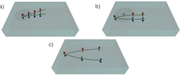
The extrinsic anomalous scattering can be categorized into skew [76, 79] and side- jump type [75]. The first assumes free electrons approximated by plane waves in the presence of spin-orbit-interaction and can be explained with classical Boltzmann transport theory [75, 80]. This is illustrated in Fig. 2.1a). An electron is incident to a spherically symmetric spin-orbit-potential. In general, time reversal symmetry is not broken (e.g. by a magnetic field) and therefore the electrons at the Fermi surface are spin degenerate. Upon the scattering event electrons are deflected asym- metrically with respect to their spin degree of freedom. The linear trajectories of spin-up and -down electrons confine an angle δ.
The second extrinsic type results from theoretic considerations when assuming Gaus- sian electron wave packets [73, 75, 81]. The electron performs a side-way movement
∆y inside the spin-orbit scattering potential of the impurity. The situation is shown schematically in Fig. 2.1b). After the scattering event the spin-split electron trajec- tories are parallel to the incident beam. Thus, viewing the scatterer as point-like the
2.1 Mechanisms of spin dependent scattering
a) b)
c)
Figure 2.1: The different spin dependent scattering types are illustrated, in a) and b) skew and side-jump scattering, respectively, and in c) intrinsic type.
In a) and b) the spin orbit coupling potentials are depicted as concentric circles around an impurity (grey). Electronic transport takes place from the left to the right in all pictures. Electrons and their spin degree of freedom are represented by yellow spheres and red and blue arrows respectively.
electron performs a side-jump. However, when assuming that the Gaussian electron wave packet is only scattered in the spin-orbit potential of an impurity but moves freely otherwise, side-jumps of only ∆y≈1×10⁻¹⁶m are expected [75]. This is too small to have physical relevance. Yet, taking into account the effective spin-orbit Hamiltonian resulting from the band structure the side-jumps reach the order of
∆y≈1×10⁻¹⁰m [75]. Hence side jump scattering can play a decisive role.
The last type of scattering considered here is exclusively due to the electronic band structure of a material. This intrinsic spin dependent scattering might dominate if the spin-orbit-coupling between bands is strong and hence a large interband con- ductivity is present [73]. In a semiclassical picture, the charge carriers acquire an anomalous velocity due to a nonzero Berry phase [73, 82, 83]. In Fig. 2.1c) this type of scattering is illustrated. The asymmetric scattering of spin-up and -down electrons is present if an electric field E is applied to a system with broken spatial inversion or time reversal symmetry. Note that for a ferromagnetic system the latter symmetry breaking is always present. Spin-orbit interaction couples spin and orbital part in spin-space and an anomalous Hall voltage is measurable [72, 83].
For intrinsic SHE the reasoning is analogous to the case of intrinsic AHE but one additionally has to account for the time-reversal symmetry breaking being present only on the scale of the system’s spin diffusion length. The detailed mechanisms of spin-orbit-coupling in crystals shall not be discussed within the frame of this thesis.
As a review consult e.g. [78]. It is noteworthy that the first calculation of intrinsic SHE assumed Rashba-spin-orbit-coupling [77] and was measured in a semiconductor
hole-gas system shortly after its prediction [38].
In the review article by Nagaosa et al. about AHE [73] different spin scattering regimes are empirically identified according to the conductivity of FM. Recent re- views about SHE [84, 85] pointed out that the regimes should be analogous for NM.
Experimentally, the measured quantity to identify different regimes of extrinsic or intrinsic scattering is the transverse resistivityρxy due to a longitudinal current Ixx through a conductor. This is summarized in the following formula, cf. [73, 86]:
ρxy =µ0(ROHz+RAnMz) (2.3)
The first term on the right hand side of Eq. (2.3) is the transverse resistivity caused by an external field Hz and the Lorentz force mediated ordinary Hall effect. The second term describes the anomalous Hall effect due to a nonzero magnetization Mz of the ferromagnetic material. RO and RAn are the corresponding Hall coeffi- cients. The investigation of ρxy with respect to the longitudinal resistivity ρxx and comparison to microscopically expected behavior of transport properties yields a classification of dominant scattering mechanism regimes [73]. From inversion of the system’s conductivity tensor one can infer that
ρxy ≈ σxy
σxx2 +σ2xy ≈ σxy
σ2xx (2.4)
making the assumption thatσxx >> σxy. The Bloch state transport lifetime τ and implications with respect to Eq. (2.4) can be compared to experimentally observed data. For skew scattering both σxx and σxy ∝τ ∝ ρ1
xx and therefore ρxy ∝ρxx. For side-jump and intrinsic scattering only σxx ∝ τ ∝ ρ1
xx and σxy is independent of τ soρxy ∝ρ2xx. From experimental data three anomalous Hall regimes are identifiable [73]. The so-called high conductivity regime where σxx > 1×10⁸Ω−1m−1 is dom- inated by skew scattering. For values 1×10⁸Ω−1m−1 > σxx > 1×10⁶Ω−1m−1 a broad impurity density independent regime due to side-jump and intrinsic mecha- nism is recognizable. For conductivities lower than 1×10⁶Ω−1m−1 the bad-metal- hopping regime prevails andρxy decreases faster than linear for increasingρxy. The microscopic origin of the bad-metal or low conductivity regime will not be discussed here, the interested reader might refer to [73] and references therein.
Bearing the different mechanism regimes of spin dependent scattering in mind the following sections are devoted to a phenomenological approach to spin Hall effects.
As one will see, from an experimental point of view this change of paradigms helps a lot.
2.2 Phenomenology of SHE and ISHE
2.2 Phenomenology of SHE and ISHE
In order to understand experimental approaches, techniques and perspectives of spin Hall effects it is useful to understand the origin and nature of charge and spin cur- rents [78, 87] and their phenomenological transformation into each other [74, 88].
The spin Hall angle αSH is introduced as the parameter to define the magnitude of spin dependent scattering. Then experimental approaches will be discussed. Poten- tials and limits will be in the focus and spin pumping is established as one of the most versatile and promising methods to study spin dependent scattering of pure spin currents via ISHE in normal metals.
2.2.1 Charge and spin currents
According to [78, 87] the time-rate of change of a particle density can be defined with respect to a random walk and is given by [78]:
∂n
∂t =D∇2n+vd∇n (2.5)
The first term on the right hand side describes diffusion of particles in terms of the diffusivity parameter D = 12v2τ. Particles moving at the velocity v are being scattered after the momentum relaxation time τ. For metallic conductors v equals the Fermi velocityvF, since only electrons at the Fermi-level participate in transport.
The second term of Eq. (2.5) accounts for the fact that particles carrying charge like electrons might be biased with an electric fieldE= mveτd = vµd;vdis the drift velocity of the charged particles, e is the charge, and the mobility of the particles is defined byµ= eτm. The connection between a particle density’s time-rate of change Eq. (2.5) and the corresponding particle current density (flux) J is given by the continuity equation:
∂n
∂t +∇(−µnE−D∇n) = ∂n
∂t +∇J= 0 (2.6)
It is equal to zero as both particle number and charge are conserved quantities of a closed system. For electrons the charge flux is defined as jc=−eJ:
jc =σE+D∇n (2.7)
where σ =enµ is the conductivity.
Drift and diffusion of a spin density is more subtle. A spin flux has both a direction and independently of it a polarization. Examining general properties of spin currents a reduction to one-dimensional transport of particles with two spin eigenstates up (|↑i) and down (|↓i) is useful [78]. From a random walk perspective spin-up and -down electron densities obey the following time-rate of change:
∂n↑
∂t =D∂2n↑
∂x2 +vd
∂n↑
∂x − w
τ(n↑−n↓) (2.8)
∂n↓
∂t =D∂2n↓
∂x2 +vd∂n↓
∂x + w
τ(n↑−n↓) (2.9)
The last terms on the right hand sides of Eqs. (2.8) and (2.9) account for the fact that for every momentum scattering event a spin-flip might occur. This is characterized by a certain transition probability w from up- to down-spin and vice versa. The total particle density is given by n = n↑ +n↓ and its time evolution is given by Eqs. (2.5)-(2.7). The interesting quantity in terms of spin transport is s=n↑−n↓, this is the particle spin density. Combining Eqs. (2.8) and (2.9) the drift-diffusion equation for a spin density is as follows
∂s
∂t =vd∂s
∂x +D∂2s
∂x2 − s
τs (2.10)
and the corresponding continuity equation is given by:
∂s
∂t + ∂
∂x(−µsE−D∂s
∂x) = ∂s
∂t − ∂
∂xJs=−s
τs (2.11)
Js is the spin particle current density. Here the parameter τs = 2wτ has been in- troduced, the so-called spin relaxation time. The fact that spin is not a conserved quantity in the system manifests itself in Eq. (2.11) where the right hand side is nonzero but consists of a spin-sink term. The characteristic length scale on which spin conserved transport takes place is given by the spin diffusion length λsd [78].
Assuming ∂s∂t =E = 0, Eq. (2.11) reduces to:
D∂2s
∂x2 = s
τs ⇔ ∂2s
∂x2 = s
λ2sd (2.12)
this defines the spin diffusion length as λsd =√
Dτs. Suppose there is a given spin density s0 at x = 0. It will evolve into a spatially dependent spin density s(x) (also called spin accumulation) into positive x-direction according to the following formula:
s(x) =s0exp− x λsd
(2.13)
If a steady state spin currentJs,0 =−D∂s(x= 0)/∂xis incident at x= 0, s(x) will be:
s(x) =Js,0
λsd
D exp− x λsd
(2.14)
and for Js(x) the following relation holds:
Js(x) =Js,0exp− x λsd
(2.15)
Note that Eqs. (2.13) and (2.15) exhibit the same qualitative behavior as a function of x. It is a matter of choice of what one wants to keep track of - the spin accumu- lation or current densities. When it comes to spin Hall effects, it is the latter.
2.2 Phenomenology of SHE and ISHE As the spin of electrons is quantized in units of ~/2 it is useful to define the electron spin flux or spin current density as follows:
js=−~
2µsE− ~ 2D∂s
∂x (2.16)
Accounting for three spatial dimensions it is essential to realize that the spin current density is a tensor quantity with the following components distinguishing transport direction (i) and spin quantization axis (j):
js,ij=−~
2µEisj− ~ 2D∂sj
∂xi (2.17)
Eqs. (2.7) and (2.17) can effectively be used to draw a phenomenological picture about what happens if spin orbit coupling is included into the considerations, [74, 88]. Spin Hall and inverse spin Hall effect are the consequence.
2.2.2 SHE and ISHE
Including spin-orbit-coupling, anomalous current densities (i.e. transverse contribu- tions) are to be included into Eqs. (2.7) and (2.17). Analogously to [74, 88] this can be done phenomenologically in component representation by the following two equations:
jc,i=jc,i(0)+ 2e
~ζijkjs,jk(0) (2.18)
js,ij=js,ij(0)− ~
2eζijkjc,k(0) (2.19)
here summation over repeated indices is assumed and ijk is the unit antisymmetric tensor, the Levi-Civita symbol, cf. [89]. jc,i(0) and js,ij(0) are given by Eq. (2.7) and (2.17), the longitudinal components of the respective current densities. The param- eterζ is a dimensionless constant proportional to the strength of spin-orbit coupling.
The different sign for the additional terms in Eqs. (2.18) and (2.19) reflects the fact of different dependencies of charge and spin currents with respect to time reversal.
Inserting Eqs. (2.17) and (2.7) into Eqs. (2.18) and (2.19) yields the two central phe- nomenological equations for charge and spin-charge-current densities in the presence of spin-orbit coupling, cf. [74, 88]:
jc,i=σEi+eD∂n
∂xi −2e
~ζijk ~
2µEjsk+ ~ 2D∂sk
∂xj
!
(2.20) js,ij= ~
2µEisj+~ 2D∂sj
∂xi − ~
2eζijk σEk+eD∂n
∂xk
!
(2.21) The first term proportional to ζ in Eq. (2.20) describes the fact that a transverse charge current is generated by a charge current carrying a net spin polarization.
This accounts for the AHE in ferromagnetic materials. The respective second term of Eq. (2.20) yields charge current generation by a spatially inhomogeneous spin density (ISHE). This situation is especially given when a pure spin current flows through a conductor. In this case the last term of Eq. (2.20) is usually written in the following equivalent form:
jc= 2e
~αSHjs×es (2.22)
Here the so-called spin Hall angle αSH = ζ is introduced. It is the dimensionless ratio of generated charge current to injected spin current density. es is the unit vector of spin polarization.
In Eq. (2.21) the terms proportional toζdescribe the phenomenon that a pure charge current generates a spin current whose direction and polarization are perpendicular to the charge current. This is usually described by the following formula containing the spin Hall angle:
js = ~
2eαSHes×jc (2.23)
Note that in Eqs. (2.22) and (2.23) js is defined as a vector entity pointing into the direction of the spin current densities. These formulae are a perfect basis for understanding experimental approaches and can be invoked for the quantification of spin Hall effects by the spin Hall angle.
2.2.3 Experimental approach to SHE and ISHE
In Fig. 2.2a) a schematic of SHE in a conductor slab is shown, cf. [34]. According to Eq. (2.23) a charge current density jc which flows along the x-direction generates a spin current densityjs along the y-axis which has a polarization pointing along the z-direction. In steady state a spin accumulation with opposite polarization builds up at they-edges of the conductor, see Fig. 2.2b). Note that this is analogous to the ordinary Hall effect where electrons flowing alongxare deflected along ydue to the Lorentz-force if a magnetic field which points along the z-direction is present. The fact that spin is not a conserved quantity manifests as the spin density falls off ac- cording to Eq. (2.13) on the characteristic length scale ofλsd. In a first approach one might assume that the dimension of the sample along the y-axis is small compared to λsd. This implies that the spin information established at one asymmetric scat- tering event is maintained throughout the conductor. The spin accumulation is only zero in the very center region of the sample, as indicated in Fig. 2.2b). Upon these circumstances Hirsch suggested in [34] to measure the spin accumulation caused by SHE via the inverse spin Hall effect (ISHE). In Fig. 2.3a) the basic idea is presented.
Due to SHE in NM there is a spin accumulation at the y-edges. Along with them comes a chemical potential difference between up- and down spins on either side.
NM is covered with an insulating material layer, which has small squares cut out at the edges. On top a second NM is deposited and connects the two opposing y-edges
2.2 Phenomenology of SHE and ISHE
a) b)
Figure 2.2: Phenomenological pictures of SHE in a conductor slab are shown. In a) the explicit transformation of a charge current jc into a transverse spin current js is explained. b) shows the steady state condition. A constant jc along thex-axis generates a spin accumulation (red, blue arrows) on the±y-edges of the conductor. The fact that the spin accumulation falls off exponentially from the edges to the center is also indicated.
of the NM underneath. The insulation layer forces the charge current exclusively through the lower NM. The chemical potential difference drives a pure spin current along the y-direction with its polarization along z in the upper NM. According to Eq. (2.22) a charge current density is generated along −x and in steady state an electrical voltage drop is detectable in x-direction across the upper NM.
Though very elegant, detecting SHE and ISHE at the same time, as well as proving the Onsager reciprocity between the two effects [39, 90], the measurement tech- nique proposed by Hirsch is difficult to be implemented for real samples. This has several fundamental reasons. The voltage detectable in a measurement scheme as presented in Fig. 2.3b) is proportional to the resistivity of the material involved and is naturally small for normal metals. Furthermore, the voltage is proportional to the magnitude of spin dependent scattering (αSH) which builds up the spin accumu- lation. On the other hand a large αSH entails a small λsd. As the preliminary basis for the measurement scheme of Fig. 2.3 is that the device’s dimensions are smaller than λsd, one runs into problems for NM with possibly large spin Hall effect. Such materials, like Pt or Pd, usually have a λsd in the range of 1 to 20 nm, [91] and it is rather impossible to prepare such small samples. It took a decade to implement Hirsch’s technique to measure SHE and ISHE. This was achieved changing the ma- terial compound from NM to a semiconductor two dimensional electron gas [92, 93].
Zhang suggested in [36] that SHE and “spin-relaxation should be studied on an equal footing”. In [36] this is done using a Boltzmann approach to spin diffusion.
Not going into detail about the theoretical technique, in the following its experi- mental implications shall be in the focus. As already mentioned above, the spin accumulation due to SHE at the edges of a conductor slab as shown in Fig. 2.2b) occurs on a length scale λsd. Therefore, in a macroscopically wide sample there
a) b)
Figure 2.3: The measurement scheme as proposed in [34] is presented. In a) a method of how to probe a spin accumulation due to SHE by ISHE is described. The spin accumulation at ±y-edges (red, blue arrows) in the lower NM drives a spin current js through the upper conductor. There js will be transformed into a charge currentjc. Also indicated is that the two conductors (light and dark gray) are separated by an electrically in- sulating layer (purple). Contact between the two conductors only takes place at the±y-edges via two holes in the insulator (marked by the black ellipsis in the schematic). In b) the open-circuit condition is shown. js generates a voltage signal in the upper conductor due to ISHE which is proportional to the spin accumulation, established by jc in the lower conductor.
is nonzero spin accumulation only at the very edges of the specimen. To this end one might think of spin layers [88]. The spin accumulation in these layers might be probed using Silsbee-Johnson spin-charge-coupling [7]. The idea is to directly attach a ferromagnetic probe to the spin accumulation [36]. For a schematic see Fig. 2.4a).
A voltage difference dependent on the relative orientation of the ferromagnetic ma- terial’s magnetization and the spin accumulation’s polarization should be detectable [7, 10, 78]. Note that the spin accumulation’s polarization could be simply reversed by reversing the charge current, see Eq. (2.23). In [36] it is estimated that one might be able to measure a voltage in the µV-range. Using the related method of nonlocal spin injection, which has been pioneered in [94] for an all-metallic mesoscopic sys- tem, finally led to the first electrical measurement of ISHE in the normal metal Al [40]. Spins are injected electrically from a ferromagnetic contact into an all-Al Hall bar structure. This leads to a spin accumulation in the Al near the FM interface.
Next to the FM-contact, within the spin diffusion length of Al, the Al is shaped as a cross having two voltage probes attached to its arms. For a layout of the mea- surement scheme, see Fig. 2.4b). The charge current is forced to flow away from the Hall cross, but the spin density diffuses into both directions of the Hall bar and
2.2 Phenomenology of SHE and ISHE
a) b)
Figure 2.4: In a) the measurement scheme to study SHE proposed by Zhang in [36]
is shown. A ferromagnetic probe (green) is brought into contact with the spin accumulation generated by SHE at the edges of a conductor.
In b) the idea of the experiment which led to the first observation of ISHE in a NM layer, cf. [40], is shown. A spin polarized charge current is injected through a ferromagnetic contact into NM. In NM the charge current jc is forced to the left in this picture. Due to its diffusive nature one is provided with a pure spin current js flowing to the left and to the right. As indicatedjs generates a voltage drop in the cross structure due to ISHE.
therefore a pure spin current flows towards the Al Hall cross. The magnetization of the FM points along the z-direction in this picture and the polarization of the spin current points parallel to it. The spin current’s polarization, its direction and the path which connects the voltage probes build a right-handed trihedron. Hence in steady state a voltage is measurable according to Eq. (2.22) along the Al-cross. This is indicated by the voltage probes in Fig. 2.4b). Note that turning the magnetiza- tion of the FM contact into the x-y-plane results in zero voltage drop, in line with Eq. (2.22) [40]. From this measurement an αSHof 0.4 - 1×10⁻⁴ has been extracted.
The promising results of [40] led to many electrical measurements of ISHE in ma- terials with possibly larger αSH [95–97]. Especially Pt and Au have been in the focus [96, 97]. For Pt the crux is that along with strong spin-orbit-coupling an enor- mously reduced spin diffusion length is expected. Actual measurements show values of λsd(Pt) = 1 - 14 nm, [54, 91], for room to liquid helium temperature. Recalling the principle method introduced in [40], i.e. the Hall cross of the material to be examined has to have a distance to the spin injector smaller than λsd. Therefore, due to nanostructure fabrication limits a Hall bar consisting completely of Pt is no option. In [96] the solution for this problem has been to insert a conductor with small spin-orbit-coupling and consequential largeλsd, in this case Cu was used [98],
a) b)
Figure 2.5: The fundamental experimental approaches for studying SHE and ISHE in FM/NM bilayers using magnetization dynamics are presented. In a) a spin accumulation is generated in the top NM layer (grey) due to SHE at the top layer’s edges. This injects a spin current into the bottom FM layer (green) which exerts a spin transfer torque on the precessing magnetization and changes the damping. This experimental method is called modulation of damping (MOD) [66]. If the charge current in NM is oscillating the spin tranfer torque can drive the magnetization (ST-FMR) [100] In b) the SP-ISHE method is depicted. A precessing magnetization in the bottom FM-layer (green) injects a pure spin current into the top NM layer (red). There ISHE converts the spin current into a transverse charge current and in steady-state a voltage drop is measurable [47].
for the spin current to be transported into Pt. This led to a corresponding value of αSH of 3.7×10⁻³. As electrical shunting in Cu, which was directly attached to Pt, has been neglected in [96],αSH(Pt) is believed to be one to two orders of magnitude larger. A review by Liu et al [54] summarizes the debate about shunting effects that reduce the experimentally extracted spin Hall angles. In fact, a recalculation of the results of [96] yields αSH(Pt) = 0.021−0.042. This reconciles at least the order of magnitude forαSH from [96] with values from alternative experimental approaches.
Alternative methods involving a combination of magnetization dynamics and elec- trical detection guide a way out of this dilemma. To this end the basic concepts are utilization of spin transfer torque (STT) [20, 21] or spin pumping [42, 44, 99]. The latter is the one of interest for the present thesis. The first can be used to probe SHE and the second for ISHE. This offers the possibility to study the reciprocity of the two effects, an issue which still has to be proved experimentally on the very same sample.
Fig. 2.5 a) shows the principle idea of experimental techniques using STT. The basic material set is a bilayer of NM and FM. A charge current which flows along they-axis in NM generates a spin accumulation along thez-direction which features a ±ex-polarization, see Eq. (2.23). The spin accumulation at the FM/NM inter-
2.2 Phenomenology of SHE and ISHE face diffuses into FM. Experimentally studied is the influence of the corresponding injected spin current on the magnetization’s dynamics. Experimental techniques differ with respect to setting up a direct or an alternating charge current. In the first case there is a constant spin accumulation at the FM/NM interface and the transferred angular momentum, along with the spin current being injected into FM, alters the damping of a precessing magnetization due to STT. This technique has lately been called modulation of damping (MOD) [85]. MOD as a measure of SHE in Pt has been used in [66] and a value of αSH= 0.08 has been determined. Setting up an alternating charge current modulates the spin accumulation at the NM/FM interface at the same frequency. If this is happening at the eigenfrequency of the magnetization, one may induce precession due to STT. Correspondingly this method is called ST-FMR. First established for magnetic tunnel junctions [101, 102], and nanomagnets [103], it has been pioneered as SHE generated ST-driving of mag- netization dynamics in [100]. The concept always relies on measuring the related modulation of magnetoresistance. Specifically, in setups analogous to the one pre- sented in [100], cf. Fig. 2.5a), it is a voltage signal measurable due to anisotropic magnetoresistance (AMR) [59]. The concept recently has been applied to Pt, Ta and W [28, 100, 104] and spin Hall angles αSH(Pt) = 0.07, |αSH(β-Ta)| = 0.12 to 0.15 and |αSH(β-W) = 0.30| have been determined. Yet, there are still unresolved issues using this technique. An elaborate discussion about microwave coupling into highly resistive materials like β-Ta and β-W is still missing. In fact, the alternative mea- surement technique of spin pumping connected with FMR yields|αSH(β-Ta)|= 0.02 [105] which is almost an order of magnitude smaller than the result from ST-FMR.
Interestingly, [105] presents comparative results of αSH of β-Ta to Pt, which shows that αSH(Pt) > αSH(β-Ta) and the result for αSH(Pt) is in line with the one pre- sented in [100]. To this end also questions about the quality and reproducibility of the examined β-Ta and β-W samples as well as of the corresponding FM/NM in- terfaces arise. The experimental method based on ST-FMR is of second order when probing SHE. In steady state a charge current in NM generates a spin accumulation;
STT drives the magnetization; this mixes the magneto resistance with the rf-current in FM and therefore a dc-voltage is detectable.
In contrast, the technique based on spin pumping is of first order when measur- ing ISHE. It is the reciprocal experiment of MOD. A precessing magnetization in FM injects a pure spin current across the FM/NM interface. The generation of a charge current in NM according to Eq. (2.22) can be directly probed in an open circuit configuration as a voltage VISHE. This is schematically shown in Fig. 2.5b).
The method shall be referenced as SP-ISHE in the present thesis. The idea of SP- ISHE has basically been introduced in [47] and qualitatively been refined in [48]
and [106, 107]. SP-ISHE has turned out to be a powerful method to study the spin Hall angle especially for materials with large spin-orbit-coupling. Hence, in the past half decade many corresponding experiments have been conducted in order to yield quantitative results for αSH. With this respect Pt is the prime example for showing the efforts, [49–53, 105, 108, 109]. However, the results for αSH of Pt are varying in a range of 0.013 [50] to 0.16 [53]. In this respect two major issues are outstanding.
On the one hand spurious effects related to experimental setups are to be taken into account thoroughly as voltage generating effects like AMR can easily be confused withVISHE. On the other hand the spin diffusion lengthλsdof Pt plays a decisive role when calculatingαSH from the data. The assumption of the same λsd for Pt partly reconciles the published values for αSH [54]. The remaining ambiguities might be successfully dissolved taking into account the spurious effects and a thorough study of λsd. The quest for materials featuring large spin Hall angles is therefore possible using SP-ISHE.
Moreover, spin pumping generates a spin current whose polarization oscillates at the magnetization’s precession frequency. Such an ac-spin current can be uniquely probed by ISHE. The theoretical prediction is that the corresponding VISHE(t) is much larger than the ISHE-signal caused by the dc-component of the spin cur- rent [63, 110]. The ac-ISHE has recently been observed implementing SP-ISHE in NiFe/Pt [64, 68]. The work presented in this publication has been one of the major aspects of the present thesis, see Chapt. 9.
3 Ferromagnetic resonance and spin pumping
For the fundamental study of ISHE, see Eq. (2.22), in normal metals (NM) it is required to inject a pure spin current. A powerful method to do so is spin pump- ing (SP) in FM/NM bilayers [42, 44, 46]. The prerequisite for SP is to operate ferromagnetic resonance (FMR) in FM. In this chapter the needed basic principles of magnetization dynamics will be explained. We shall start off with fundamental aspects on magnetic moments and magnetization and then head on towards micro- magnetism, cf. [111], and the characteristics of thin ferromagnetic films. It will always be kept track of the special properties of NiFe, the FM of choice through- out this work. Specifically, the magnetization dynamics of thin ferromagnetic films without in-plane anisotropies (NiFe) will be treated. The phenomenological Landau- Lifshitz-Gilbert (LLG) equation is introduced in order to describe the time-evolution of the magnetization, [112, 113]. Thence, the application of an oscillating external magnetic field will be incorporated into the considerations and ferromagnetic res- onance (FMR) for thin magnetic films will be elaborated cf. [114–117]. At its heart this comprises the characterization of FMR via the Lorentzian-like line shapes of the involved dynamic susceptibilities [116]. Special attention is devoted to the extraction of parameters characterizing FM-films in terms of gyromagnetic ratio, effective magnetization, and dissipation of energy, viz. damping. These parameters are essential to quantify SP. Then, following the theoretical work of [41–43], SP is introduced as an analog of charge pumping through mesoscopic systems [118–
121]. Spin currents transported across FM/NM interfaces are to be characterized by the spin mixing conductance. To this end the relevant concepts of circuit theory [122, 123] and non-collinear magnetoelectronics [124–126] will be reviewed. In the final part of this chapter the spin currents from SP will be characterized by their specific line shapes across FMR. This comprises both dc- and ac-components.
3.1 Magnetic moments and magnetization
The distinct feature of a ferromagnetic material is its nonzero magnetization M, which is present even without an external magnetic field Hext [111, 127]. M is the magnetic momentmdivided by the volume V of the material. The archetype of m is a current loop. In this perception, which was brought forward by Ampère, the magnetic moment is defined as follows [111]:
m=IAen (3.1)
I is the current around the circumference of an area A, whose orientation is parallel to the normal unit vector en. Particularly, any charge whose movement is along a curved trajectory corresponds to a certain amount of magnetic moment. This is especially true for electrons orbiting an atom’s nucleus. The link between magnetic moment mand angular momentum lis the so called gyromagnetic ratio γ:
m=γl (3.2)
Assume one electron orbiting an atomic nucleus. In a semiclassical approach to this problem it is used thatl=r×pand that the momentum p is quantized in units of
~. This yields the quantum for magnetic moments in atoms [127].
µB = e~
2me (3.3)
µB is called Bohr magneton, e and me are the electron’s charge and mass, respec- tively. Furthermore, the general equation
m=− e
2mel=γl (3.4)
holds. This defines γ = −2me
e. The minus sign indicates that the magnetic mo- ment and the respective angular momentum are antiparallel due to the electron’s negative charge. The semiclassical viewpoint presented here provides an intuitive starting point for a correct quantum mechanical description of the magnetic moment.
In quantum mechanics physical observables are represented by Hermitian operators which are defined analogously to their classical counterparts [128]. Experimentally it is the operators’ eigenvalues which are measured. After one measurement process the system’s state, which is described by a vector in Hilbert space, changes or col- lapses into an eigenstate corresponding to the measured physical observable. This implies that two physical entities can only be measured at the same time if they have joint eigenstates or equivalently if the corresponding Hermitian operators com- mute. As a matter of fact, the only information one can gather simultaneously from a measurement of angular momentum of an electron orbiting an atomic nucleus is its magnitude and its projection on one coordinate axis, which is usually referred to as the z-axis. The corresponding operators areˆl2 and ˆlz and their eigenstates are
3.1 Magnetic moments and magnetization denoted as |lmi. The hat indicates that one deals with an operator and the eigen- state is represented in Dirac-notation. The eigenvalues are given by the following two equations, [127]:
ˆl2 =~2l(l+ 1)|lmi, l = 0,1,2, ... (3.5) ˆlz =~ml|lmi, ml=−l, ..., l (3.6) l is the angular momentum and ml the so-called magnetic quantum number. ml has 2l+ 1 possible values ranging from −l to +l in steps of 1. Using Eq. (3.4), the eigenvalues of the magnetic moment operator ˆmz due to orbital electronic motion are given by:
mz =γ~ml=−µBml (3.7)
Yet, for the magnetic moment of electrons this is only half of the story. There is a second contribution for which there is no classical analog. It is of pure quantum mechanical nature; the electron’s spin. With many respects, yet not with all, spin can be treated analogously to angular momentum. The corresponding operators are ˆs2 and ˆsz. For an electron the magnitude of spin is given by s = 12 and therefore ms=±12. For the magnetic moment assigned with spin the following relation holds:
mz =γs~ms =−gµBms (3.8)
It differs from Eq. (3.8) with respect to γs =gγ. The so calledg-factor accounts for the fact that spin has a different efficiency in creating magnetic moment as orbital angular momentum. Assuming g = 2, one realizes that both orbital motion and spin generated magnetic moment are quantized in units of µB.
Accounting for both orbital angular momentum and spin the magnetic moment operator ˆm for a single electron is given by:
ˆ
m=γ(ˆl+ 2ˆs) =gjγˆj (3.9)
ˆj = ˆl+ ˆs is the overall angular momentum operator and gjγ = γj is the relevant proportionality factor linking magnetic moment and overall angular momentum.
So far only a single electron has been considered. A conceptual transfer to a multi- electron system may be performed by introducing overall operators ˆl →Lˆ, ˆs→ Sˆ, ˆj →Jˆ. From this the so-called Landé g-factor gJ is given by [111]:
gJ= 3
2 +S(S+ 1)−L(L+ 1)
2J(J + 1) (3.10)
S, L and J = L+S can be estimated applying Hund’s rules filling the elemental electron orbitals. Yet, being exact for single atoms and a good approximation for solid state materials with strongly localized valence electron orbitals viz. 4f, these
rules ultimately fail for 3d-transition-metals. This is especially true for the 3d- ferromagnets Fe, Co and Ni. The orbital angular momentum is quenched in such materials due to the strong Coulomb interaction ofd-orbitals with their environment and the total angular momentum per atom is well approximated by S plus taking into account electron transfer from the s- into the much narrower d-band at the Fermi surface. The corresponding large density of statesD(EF) near the Fermi level results in an energy gain for the d-band when splitting into d↑- and d↓-band, [111].
E.g. for Fe crystallized in bcc-structure the valence electrons per atom are given by 3d7.44s0.6, the spin-split configuration is 3d↑4.83d↓2.6 and the magnetic moment per atom is given by matom, Fe = 2.2µB. For Co and Ni the atomic moments per atom are given by matom, Co = 1.7µB and matom, Ni = 0.6µB respectively, see [111].
These values can readily be used to determine the magnetic moment per atom for NiFe. Weighted averaging accounts for different compositions. The result for the most common composition Ni80Fe20 is matom, NiFe = 0.92µB. The expected values for the saturation magnetizationMS of a material can be calculated by multiplying the number of atoms per unit volume with the magnetic moment per atom. Thus, µ0MS,NiFe = 0.96 T.
The interaction between a magnetic moment m and a magnetic flux density B is classically given by, cf. [111, 127]:
Γ=m×B (3.11)
|Γ|=|m×B|=mBsin(Φ) (3.12)
E =Z Φ
0 dΦ0mBsin(Φ0) =−mB (3.13)
Γ is the torque acting on m. The stored energy is given by integrating Γ with respect to the angle Φ between m and B, see Eq. (3.13). Quantum mechanically the interaction is described by the so called Zeeman-Hamiltonian:
HˆZee =−γ(ˆl+ 2ˆs)B (3.14)
The definition of the magnetic moment as a consequence of angular momentum, see Eq. (3.2) together with the fact Γ = dl/dt leads to the following equation of motion for m:
dm
dt =γm×B (3.15)
In order to transfer this result to the dynamics of a magnetizationM(r, t) one has to think about the consequence of inserting magnetized media intoB. To this end the auxiliary fieldHis introduced [111, 127]. This leads to two fundamentally different equations describingB in free space and in a magnetized medium respectively:
B=µ0H (3.16)
B=µ0(H+M) (3.17)
![Figure 2.4: In a) the measurement scheme to study SHE proposed by Zhang in [36]](https://thumb-eu.123doks.com/thumbv2/1library_info/5554915.1689147/23.892.123.744.114.374/figure-measurement-scheme-study-proposed-zhang.webp)