Spin dynamics in p-doped semiconductor nanostructures subject to a magnetic field tilted from the Voigt geometry
K. Korzekwa,1,2,*C. Gradl,3M. Kugler,3S. Furthmeier,3M. Griesbeck,3M. Hirmer,3D. Schuh,3W. Wegscheider,4 T. Kuhn,5C. Sch¨uller,3T. Korn,3and P. Machnikowski2
1Department of Physics, Imperial College London, London SW7 2AZ, United Kingdom
2Institute of Physics, Wrocław University of Technology, 50-370 Wrocław, Poland
3Institut f¨ur Experimentelle und Angewandte Physik, Universit¨at Regensburg, D-93040 Regensburg, Germany
4Solid State Physics Laboratory, ETH Zurich, 8093 Zurich, Switzerland
5Institut f¨ur Festk¨orpertheorie, Westf¨alische Wilhelms-Universit¨at, D-48149 M¨unster, Germany (Received 16 July 2013; published 8 October 2013)
We develop a theoretical description of the spin dynamics of resident holes in ap-doped semiconductor quantum well (QW) subject to a magnetic field slightly tilted from the Voigt geometry. We find the expressions for the signals measured in time-resolved Faraday rotation (TRFR) and resonant spin amplification (RSA) experiments and study their behavior for a range of system parameters. We find that an inversion of the RSA peaks can occur for long hole spin dephasing times and tilted magnetic fields. We verify the validity of our theoretical findings by performing a series of TRFR and RSA experiments on ap-modulation doped GaAs/Al0.3Ga0.7As single QW and showing that our model can reproduce experimentally observed signals.
DOI:10.1103/PhysRevB.88.155303 PACS number(s): 78.67.De, 78.55.Cr, 78.47.D−
I. INTRODUCTION
In recent years, it has become evident that spin dynamics of carriers in low-dimensional semiconductor structures can be studied in a controlled way by optical means.1,2 Apart from the general interest in understanding the often nontrivial kinetics of spin precession and decoherence, the optical studies of semiconductor spin dynamics are motivated by possible applications in spintronics3–5and spin-based quantum information processing.6 From the point of view of these applications, the extended coherence time of holes confined in quantum dots7–9and localized in quantum wells (QW),10–13 resulting from suppression of the major spin dephasing channels in confined systems, seems to be very promising and encourages investigation of these systems, both experimental and theoretical.
Among the optical methods used in these investiga- tions, the time-resolved magnetooptical Faraday/Kerr rotation (TRFR/TRKR)14 and the related resonant spin amplification (RSA)15 techniques have been shown to yield particularly rich information on the coherent dynamics and dephasing of electron and hole spins. The use of spectrally narrow lasers with picosecond pulse length allows for selective, resonant excitation of, e.g., exciton or trion transitions,16,17 as well as nonresonant excitation with well-defined excess energy.18,19 In TRFR/TRKR experiments, a pump-probe measurement scheme is employed, and the observable time window is typically limited to a few nanoseconds, making accurate measurements of long spin dephasing times difficult. The RSA technique utilizes the interference of spin polarizations created in a sample by subsequent pump pulses to circumvent this limitation of TRFR. A variable in-plane magnetic field is used to induce spin precession, and the Faraday rotation angle is measured for a fixed time delay. For certain magnetic field values, constructive interference of spin polarizations occurs, giving rise to characteristic maxima in the Faraday rotation signal. Even though this RSA signal is typically recorded for
a large delay between pump and probe pulses, its shape is strongly influenced by the combined carrier and spin dynamics during the photocarrier lifetime,13,17,19 and may also reflect anisotropic spin dephasing.20,21
While many of the experimental results can be accounted for by relatively simple models,12,13full understanding of the role of various microscopic factors underlying the observed dynamics, including theg-factor anisotropy and channels of dephasing, requires a more formal theoretical modeling. Such models were proposed forn-doped22 andp-doped23systems, rigorously relating the observed optical response to the precession and decay of the optically induced spin polarization in the sample. It was pointed out23that the optically manifested spin dynamics becomes particularly rich if the magnetic field is tilted from the in-plane (Voigt) orientation, leading to the coexistence of oscillating and exponential components in the Faraday response. The theory was subsequently extended to model the RSA response of confined holes and electrons.19,24,25 In the latter case, it was again pointed out that the shape of RSA signals is very sensitive to the magnetic field orientation deviating from the exact Voigt geometry.
Here, we present time-resolved studies of the combined electron and hole spin dynamics in ap-modulation doped QW subject to a magnetic field tilted from the Voigt geometry.
Using the Markovian master equation we develop a theoretical description of the spin dynamics and find analytical expres- sions for signals of two widely employed magnetooptical experiments: the time-resolved Faraday rotation and the resonant spin amplification. We identify the physical processes responsible for the formation of the signals and discuss their behavior dependent on the parameters of the system. We also point out the possibility for the emergence of inverted RSA peaks induced by a tilted magnetic field, when the spin de- phasing time is long enough. Finally, we verify our theoretical findings by performing a series of experimental measurements on GaAs-basedp-doped single QWs and demonstrate that the model can account for all experimentally observed features of
both signals. Results presented here generalize our former findings on magnetooptical experiments in tilted magnetic fields23 by finding the angular dependence of the hole spin decoherence rates in the TRFR experiment and extend the description to include the RSA experiment.
The paper is organized as follows. In Sec.II, we introduce the theoretical model describing the TRFR and RSA responses of thep-doped QW. Next, in Sec.III, we present the sample used in our experiment and describe the experimental setup and methods used. SectionIVcontains the physical interpretation and discussion of the theoretical results together with the analysis of the experimental measurements based on our model. Finally, Sec.Vconcludes the paper.
II. THEORETICAL MODEL
It is known that the experimentally measured Faraday signal gives access to the spin polarization of the sample at the arrival of the probe pulse.22,23Therefore, in order to interpret the experimental observations, we focus on the underlying microscopic electron and hole spin dynamics. Based on the previous experimental findings12,26and our recent theoretical works19,23we model the system in the following way.
The optical response is assumed to come from independent hole-trion systems, trapped in QW fluctuations and restricted to the two lowest spin states (due to the large heavy-light hole splitting in confined systems the description is restricted to the heavy-hole states, treated as a pseudo-spin-1/2 system). Each such system is represented by a density matrixρrestricted to the four states|↑,|↓,|T↑,|T↓, representing the two hole states and the two trion states with different spin orientations (with respect to the normal to the sample plane). The density matrix is parametrized by introducing the set of dynamical variables:
Nh/t=Tr σ0(h/t)ρ
, (1a)
Xh/t=Tr σ1(h/t)ρ
, (1b)
Yh/t=Tr σ2(h/t)ρ
, (1c)
h/t=Tr σ3(h/t)ρ
, (1d)
where σi(h/t) are Pauli operators restricted to hole/trion sub- space (σ0 is an identity operator). The Hamiltonian of the system placed in a magnetic field oriented at an angle θ with respect to the growth axis, B=B(sinθ,0,cosθ), and in a reference frame rotating with the zero-field hole-trion transition frequency (which we will use throughout this work) is given by
H0= −12μBBgˆhσ(h)−12gtμBB·σ(t), (2) whereμBis the Bohr magneton, ˆghis the hole Land´e tensor, andgt is the Land´e factor of the trion (i.e., of the electron), which is assumed to be isotropic. This assumption is justified as the anisotropy of the electrongfactor observed experimentally in a narrow quantum well27does not play an important role for the small tilt angles that are considered in this work (the change of the effective electron gfactor is less than 1%). The hole Land´e tensor is assumed to have no in-plane anisotropy, so it is characterized by the in-plane componentg⊥(perpendicular to the normal to the QW plane) and the out-of-plane component
g(parallel to the normal to the QW plane). Then, introducing the effective hole Land´e factor ˜g=(g⊥2 sin2θ+g2cos2θ)1/2 and the angleφsuch that tanφ=(g⊥/g) tanθ(which is the angle between the growth axis and the hole spin quantization axis, as the latter one does not necessarily coincide with the field orientation) this Hamiltonian may be rewritten in its eigenbasis:
H0 =12¯hωh(|−−| − |++|)
+12hω¯ t(|T−T − | − |T+T + |), (3) where ¯hωh=gμ˜ BB, ¯hωt=gtμBB, and
|+ =cosφ
2|↑ +sinφ 2|↓,
|− = −sinφ
2|↑ +cosφ 2|↓,
|T+ =cosθ
2|T↑ +sinθ 2|T↓,
|T− = −sinθ
2|T↑ +cosθ 2|T↓.
Having described the system we now proceed to the description of its evolution. This is divided into two steps:
first, the driven evolution under the pump pulse, and then the free evolution treated in an open quantum system for- malism, i.e., Larmor precession, recombination, and spin decoherence.
The coupling of the hole and trion states by the circularly polarized (σ+) laser field is treated in the dipole approximation and the corresponding Hamiltonian in the rotating wave approximation is given by
Hl= 12f(t)|↑T↑| +H.c., (4) where f(t) is the pulse envelope function. Assuming that the pump pulse is low power and short enough, i.e., much shorter than any relevant time scale of the system dynamics, the transformation it induces is described as instantaneous and up to the second order in the pulse amplitude,
ρ1 = −i
¯ h
∞
−∞dt[Hl(t),ρ0]
− 1
¯ h2
∞
−∞
dt ∞
−∞
dt[Hl(t),[Hl(t),ρ0]], (5) whereρ0is the initial state of the system andρ1is the state just after the arrival of the pump pulse. For the TRFR experiment ρ0 is the thermal equilibrium state ρeq (since the evolution after each laser repetition is independent), for which all trion variables are zero and the hole variables are parametrized by equilibrium spin polarization along hole spin quantization axis,
p= +|ρeq|+ − −|ρeq|− =tanh hω¯ h
2kBT
, so thath(eq)=pcosφandX(eq)h =psinφ.
The free evolution in between the pump and probe pulses is modeled using the Markovian master equation,
˙ ρ = −i
¯
h[H0,ρ]+L[ρ], (6)
with the initial condition given byρ1. In Eq.(6)the first term accounts for the spin precession and the dissipative dynamics is described by universal Lindblad superoperatorL=Lh+Lr. Here Lh is the hole spin dissipator, Lr is the spontaneous emission generator, and no trion spin dissipator is included as it is assumed that the radiative decay rate is much larger than any trion decoherence rates.
The hole spin dissipatorLh is obtained using the standard weak-coupling approach28 from the hole spin-environment Hamiltonian,
Hint=σ+(h)R(h)− +σ−(h)R+(h)+σ0(h)R0(h), (7) whereσ+(h)=(σ−(h))†= |+−|and the environment operators are defined by
R−(h)=R(h)x cosφ−iRy(h)−Rz(h)sinφ, R+(h)=R(h)x cosφ+iRy(h)−Rz(h)sinφ, R0(h)=R(h)x sinφ+Rz(h)cosφ.
The above environmental operators are expressed in terms of operators defined by the system structure to allow us to use the system symmetry in order to achieve considerable simplifica- tions (see below). Using this spin-environment Hamiltonian the following dissipator is obtained:
Lh[ρ]= −π
lj
Rlj(h)(ωj)
σl(h)σj(h)ρ−σj(h)ρσl(h) +Rlj(h)(−ωl)
ρσl(h)σj(h)−σj(h)ρσl(h) , (8) wherel,j = ±,0,ω0=0,ω+= −ω−=ωh, and the spectral densities for the hole reservoir are defined as
R(h)lj (ω)= 1 2πh¯2
dt eiωt
R(h)l (t)Rj(h)
, l,j = ±,0.
Now the aforementioned simplification of spectral densities can be obtained by assuming theC4vsymmetry of the system and settingR(h)αβ(ω)=0 forα,β=x,y,z;α=βandRyy(h)(ω)= R(h)xx(ω).
The spontaneous emission generatorLr, accounting for the radiative recombination of the trion, has a standard form,
Lr[ρ]=γ
σ−(↑)ρσ+(↑)−12{σ+(↑)σ−(↑),ρ}+
+σ−(↓)ρσ+(↓)−12{σ+(↓)σ−(↓),ρ}+ , (9) whereγis the radiative decay rate,σ+(↑)=(σ−(↑))†= |T↑↑|, and σ+(↓)=(σ−(↓))†= |T↓↓|. Note that no pure dephasing rate is included, as trion coherence contributes neither to the TRFR nor to the RSA signal.
This derivation is based on the one presented in Ref.23, however, with a significant difference. Namely, no secular approximation is used for the spin dynamics, so the description for arbitrary Larmor frequencies (magnetic fields) is obtained.
Although later we use some approximations based on the the magnitude of the magnetic field, omitting this kind of approximation at the level of the derivation of the equation of motion preserves the angular dependence of decoherence rates, which is otherwise lost.
The equation of motion for the density matrix, Eq.(6), can be rewritten in terms of the dynamical variables defined by Eqs.(1a)–(1d). The differential equations for trion variables
obtained in this way can easily be solved and the solutions for trion populationNt, and spin polarizationt, are given by
Nt(t)=Nt(0)e−γ t, (10a)
t(t)=t(0)e−γ t(cos2θ+sin2θcosωtt). (10b) The dynamics of the hole variables is governed by the following set of differential equations:
˙ h= −
3+cos 2φ
2 κx+1−cos 2φ 2 κx0
h
−
κx−κx0 2
sin 2φXh−ωhsinφYh
−2κxcosφNt+γ t, (11a)
˙ Xh= −
1−cos 2φ
2 κz+1+cos 2φ
2 κz0+κx
Xh
−κz−κz0
2 sin 2φh+ωhcosφYh+(κx−κz) sinφNt, (11b) Y˙h= −
1+cos 2φ
2 (κz0+κx)+1−cos 2φ
2 (κx0+κz)
Yh +ωhsinφh−ωhcosφXh, (11c) where new hole variablesh,Xhwith subtracted equilibrium values ((eq)h andX(eq)h ) are used and the decoherence rates (for α=x,z) are
κα=2π[Rαα(ωh)+Rαα(−ωh)], (12a) κα=2π[Rαα(ωh)−Rαα(−ωh)], (12b)
κα0=4π Rαα(0). (12c)
In order to find the physical meaning of these decoherence rates we consider three limiting situations. For B=0 the decoherence time for the out-of-plane component of spin polarization isTz(0)=1/2κx0and for the in-plane component it isTxy(0)=1/(κx0+κz0). In the case of strong in-plane magnetic field (ωhκα,κα,κα0 andθ=φ=π/2) the spin relaxation timeT1and the spin dephasing timeT2are given by
T1(x)= 1 κx+κz
≡ 1
κ1⊥, (13a)
T2(x)= 2
κx+κz+2κx0 ≡ 1
κ2⊥. (13b) For the strong out-of-plane magnetic field (ωhκα,κα,κα0 andθ=φ=0) these times are given by
T1(z) = 1 2κx
≡ 1
κ1, (14a)
T2(z) = 1
κx+κz0 ≡ 1
κ2. (14b)
Based on the results from Refs.22and23, we connect the rotation of the polarization plane of the transmitted probe pulse with the difference of hole and trion spin polarization,
=t−h. (15)
In order to model the TRFR experiment we analytically solve the set of differential equations, Eqs. (11a)–(11c),
and approximate the final solution for h by assuming that hole decoherence rates are smaller than the other dynamical parameters of the system. This approximation is plausible, as TRFR experiments are usually performed in magnetic fields for which the precession period is much shorter than the hole spin decoherence time. In this way we obtain the following expression for the Faraday signal,
(Faraday) =t(t)−(A1e−γ t+A2e−(γ+iωt)t
+B1e−κ1t+B2e−(κ2+iωh)t+c.c.), (16) wheret(t) is given by Eq.(10b), new decoherence rates are
κ1 =κ1⊥sin2φ+κ1cos2φ, (17a) κ2 =κ2⊥sin2φ+κ2cos2φ, (17b) and
A1= −1 2
ω2hcos2φ+γ2
ω2h+γ2 cos2θ t(0), A2= −1
2 γ γ+iωt
ω2hcos2φ+(γ +iωt)2
ω2h+(γ+iωt)2 sin2θ t(0), B1= 1
2
ωt2cos2θ+γ2
ω2t +γ2 cos2φt(0)+1
2cos2φh(0) +1
4sin 2φXh(0), B2= 1
2 γ γ −iωh
ωt2cos2θ+(γ−iωh)2
ω2t +(γ−iωh)2 sin2φt(0) +1
2sin2φh(0)−1
4sin 2φXh(0)+ i
2sinφYh(0).
In the RSA experiment the system repetitively undergoes the two-step evolution described before, with the time periodtr given by the repetition rate of the pump laser. The experiment is usually performed in the long spin dephasing time (SDT) regime, i.e., the SDT is longer thantr, so the spin polarization surviving between subsequent laser repetitions is essential.
Therefore, in order to model the RSA response, the fixed point of the two-step transformation (pump pulse and Lindblad evolution during the repetition interval tr) of the dynamical variables is found. A series of approximations is also applied in order to obtain a concise expression for the stationary spin polarizations. First of all, it is assumed that only hole spin polarization contributes to the RSA signal, as tr is much longer than the radiative decay time and no trion population survives until the arrival of the probe pulse. Next, the assumption is made that the hole spin decoherence rates are small compared to the trion recombination rate, which is a reasonable assumption taking into account the long SDT observed in experiments. It is also assumed that the hole Larmor frequency is larger than the decoherence rates, which requires justification. To justify this approximation, let us note that the first RSA peak occurs for ωh=1/tr and also, due to the long SDT regime,tr < τ, whereτ stands for the effective hole decoherence time. Hence, the only discrepancies between the modeled and measured signal introduced by this approximation can occur between zero magnetic field and the first RSA peak. It is also assumed that p1, i.e., that the experiment is done in the high-temperature regime in the sense
¯
hωhkBT, which is the usual case for the range of magnetic
fields used in the RSA experiments, as the temperature in experiments varies from hundreds of millikelvins to a few kelvins. Finally, we limit our considerations to magnetic fields slightly tilted from the Voigt geometry for which cos2θ1.
To understand the physical meaning of this approximation, let us recall thatθ defines the quantization axis for trion spins.
However, trion spins do not contribute to the RSA signal; their only contribution is to remove some of the hole polarization during recombination.12Neglecting cos2θfor small tilt angles is thus equivalent to assuming that trions precessing around the slightly tilted axis remove on average (during their lifetime) holes of approximately the same polarization as without tilting.
On the other hand, due to the strong anisotropy of the hole g factor, even small tilting results in hole spin precession around a significantly different axis, which is accounted for by preserving terms proportional to cos2φ. The expression for the RSA signal resulting from the procedure described above is given by
(RSA) =
3
i=1Aie−λitr −5
i=4Aie−λitr +c.c.
Q 3i=1e−λitr−5
i=4e−λitr+c.c.
−1, (18) where
λ1 =κ1, λ2=κ1+2κ2, λ3=κ2+iωh, λ4 =2κ2, λ5=κ1+κ2+iωh,
and
A1 =cos2φω2t((ωh+ωt)2+γ2)((ωh−ωt)2+γ2)
ω2h+γ2 , A2 =
ω2h+γ2
ω2h−ωt22 +γ2
ω2h+ω2t
ω2t +γ2
−cos2φωh2γ2
ωh2−3ω2t +γ2 , A3 =sin2φ
ω2t +γ2
ωh2+γ2
(ωh−iγ)2−ωt2
×
ω2h+iγ ωh−ω2t , A4 =sin2φ
ω2t +γ2
ω2h+γ2
ω2h−ω2t2 +γ2
ωh2+ω2t , A5 =
(ωh−iγ)2−ω2t
ω2h+γ2
ω2h+iγ ωh−ω2t
×
ω2t +γ2
+cos2φ
ωt2ωh2−ω2hγ2+3iω2tγ ωh
−iγ3ωh−ωt4−γ2ω2t , Q=
ω2t +γ2
ω2h+γ2
((ωt−ωh)2+γ2)
×((ωt+ωh)2+γ2).
III. SAMPLE STRUCTURE AND EXPERIMENTAL METHODS
All measurements are performed on samples containing a single-sidep-modulation-doped GaAs/Al0.3Ga0.7As QW with a width of 4 nm grown by molecular beam epitaxy (MBE).
The two-dimensional hole system (2DHS) in the QW has a hole density p=1.1×1011 cm−2 and mobility μ=1.3× 104cm2/Vs (measured at 1.3 K). To allow for measurements in transmission, the samples are first glued to a sapphire substrate and then thinned by mechanical grinding followed by selective wet etching. The sample structure contains a
short-period GaAs/AlGaAs superlattice, which serves as an etch stop.
A pulsed Ti-sapphire laser system generating pulses with a length of 1 ps and a spectral width of about 2 meV is used for the optical measurements. The laser energy is tuned to resonantly excite the trion transition in our sample. The repetition rate of the laser system is 80 MHz, corresponding to a time interval oftr =12.5 ns between subsequent pulses.
The laser pulses are split into a circularly polarized pump beam and a linearly polarized probe beam by a beam splitter.
A mechanical delay line is used to create a variable time delay between pump and probe. Both beams are focused to a diameter of about 80 μm on the sample using an achromat.
In the TRFR and RSA experiments, the circularly polarized pump beam is generating electron-hole pairs in the QW, with spins aligned parallel or antiparallel to the beam direction, i.e., the QW normal, depending on the helicity of the light.
In the TRFR measurements, the spin polarization created perpendicular to the sample plane by the pump beam is probed by the time-delayed probe beam via the Faraday effect:
The axis of linear polarization of the probe beam is rotated by a small angle, which is proportional to the out-of-plane component of the spin polarization.22,23 This small angle is detected using an optical bridge. A lock-in scheme is used to increase sensitivity. The RSA technique is based on the interference of spin polarizations created in a sample by subsequent pump pulses. It requires that the spin dephasing time is comparable to the time delay between pump pulses.
For certain magnetic fields applied in the sample plane, the optically oriented spin polarization precesses by an integer multiple of 2πin the time window between subsequent pump pulses, so that constructive interference occurs. This leads to pronounced maxima in the Faraday rotation angle measured for a fixed time delay as a function of the applied magnetic field. In our measurements, the time delay is chosen to probe the spin polarization remaining within the sample 100 ps before the arrival of a pump pulse.
Both, RSA and TRFR measurements are performed in an optical cryostat with 3He insert, allowing us to lower the sample temperatures below 400 mK and to apply magnetic fields of up to 11.5 Tesla. Here, the samples are cooled by cold
3He gas. The samples are mounted on a sample rod within the cryostat and can be rotated manually with respect to the magnetic field orientation. The rotation angle is measured with high precision using a laser pointer mounted to the sample rod.
As all measurements are performed in transmission geometry, the sample can be rotated without any changes to the optical beam path.
IV. RESULTS AND DISCUSSION
In this section, we present the physical interpretation of the obtained expressions for the TRFR and RSA signals and discuss their behavior in different limits of the model parameters. We also present experimental results and show that our modeling is able to reproduce experimentally measured TRFR and RSA signals in tilted fields. We first discuss the results for TRFR and then proceed to RSA.
A. Time-resolved Faraday rotation
The physical meaning of the terms appearing in the expression for the Faraday response in a tilted magnetic field, Eq.(16), will now be explained. First of all, since in a tilted magnetic field, the quantization axis for holes (trions) forms the angleφ(θ) with the structure axis, a nonzero component of the optically oriented hole (trion) spin polarization along the quantization axis exists. Therefore, the spin polarization should split into two parts: nonprecessing along the quanti- zation axis (which coincides with magnetic field axis for the electrons, but, due to the strongly anisotropic holegfactor, does not for the holes) and precessing, perpendicular to this axis. This is reflected in the analyzed Eq.(16): The precessing parts of both trion and hole polarizations [coefficients A2, B2, and Eq.(10b)] are proportional to sin2θor sin2φand the nonprecessing components [coefficientsA1,B1, and Eq.(10b)]
are proportional to cos2θ or cos2φ. Secondly, let us note that Eq.(16)can be divided into the short-living component, decaying with the recombination rateγ, and the long-living component, with its decay rate proportional to the hole spin decoherence rates. This results from the fact that, due to the difference in precession frequencies ωh and ωt, during recombination not only optically oriented holes are removed, but also resident holes. Therefore, the trion spin polarization and part of the hole spin polarization decays on the time scale of the recombination time (the short-living component), whereas the other part of the hole spin polarization survives the recombination process (the long-living component). This mechanism of creating long-living spin polarization was first described in Ref.12.
Now let us focus on the dependence of the modeled Faraday response on the magnetic field tilt angle. Since the electron g factor is assumed isotropic, the trion precession frequency ωt is not affected by the tilting. However, due to the anisotropy of the hole g factor, the hole precession frequency ωh changes. As the out-of-plane component of the hole g factor g in the considered structure is larger than the in-plane component g⊥, tilting the magnetic field from the Voigt geometry results in an increase of the hole precession frequency. This does not only shorten the period of the Faraday signal oscillation, but also changes the dephasing parameters, since they depend on the spectral densities of the reservoir at the frequencyωh [see Eqs.(12a)–(12c)]. As already mentioned, the short-living component of the Faraday signal decays with the angle-independent rateγ, however, the long-living component decays with ratesκ1 (nonprecessing part) andκ2(precessing part). By comparing the expressions for these rates, Eqs.(17a)and(17b), with the expressions for T1 andT2 times in the limiting situations, Eqs.(13a),(13b), (14a), and(14b), one can find the following. The decay rate of the nonprecessing component in the tilted field (inverse of the effectiveT1 time) is a weighted average of the decay rates for magnetic fields applied only alongx(inverse ofT1(x)) and only alongz(inverse ofT1(z)), with weights being thex andzcomponents of the unit vector parallel to quantization axis. The same holds for the precessing component and the corresponding effectiveT2time.
In order to verify that our model correctly describes the TRFR experiment, we performed a series of measurements.
0 600 1200 1800
Faraday signal (arb. units)
t (ps)
(a) θ=90o
φ=90o
θ=89o φ=76.3o
θ=88o φ=64.1o
θ=85o φ=39.4o
0 600 1200 1800 t (ps)
(b) θ=90o
φ=90o
θ=89o φ=77.9o
θ=88o φ=66.8o
θ=85o φ=43.0o
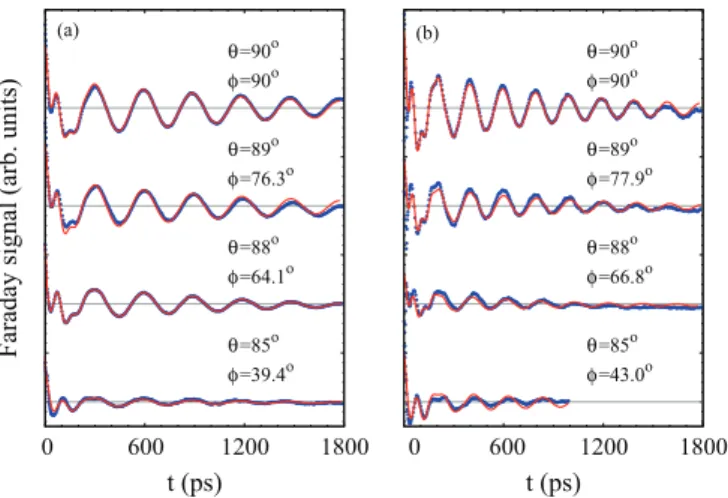
FIG. 1. (Color online) Experimental (black dots) and modeled (red lines) Faraday signals in tilted magnetic fields for different precession periods: (a)τ1≈300 ps and (b)τ2≈200 ps.
Due to the described dependence of the hole dephasing parameters on the magnetic field tilt angle, the TRFR measure- ments were performed in the following way. Simultaneously with the increase of the magnetic field tilt angle, the field amplitude was decreased, in order to keep the hole precession frequencyωhconstant. In this way, the dephasing rates were kept constant, which allowed us to use the same fitting parameters (κ1,κ1⊥,κ2,κ2⊥) for different tilt angles, so that the effective T1 and T2 times were known functions of the angle φ. Two series of experimental measurements in tilted magnetic fields were performed, for two different hole precession frequencies. These corresponded to two values of the in-plane (zero tilt angle) magnetic field,B1=3.5 T and B2=5 T, and precession periods (τ =2π/ωh),τ1≈300 ps andτ2≈200 ps. In each series, the tilt angle was changed from 0o(θ=φ=π/2) up to 5o and the temperature was set toT =1.2 K. The experimental data and the corresponding fitted curves, for both series of measurements, are shown in Fig.1. The fitting parameters used for all angles in a given series were the same. The difference in theφ angles for the sameθangles between two series comes from the difference of the fitted out-of-plane component of the holegfactor (which in turn results from the fact that in the two experimental series, different positions on the sample with slightly different QW thickness and corresponding changes ing are investigated).
As can be seen in Fig. 1, the experimental data are well reproduced by Eq. (16). This is true not only for the long time scale signal behavior (after the recombination of the trions), but also for the fine details of the initial part of the traces, when the signal comes from the coupled dynamics of the trion and hole spins. The range of parameters for which the experimental data is reproduced is, however, too wide (because of too many free fitting parameters) to make the procedure completely definite and infer the values of dephas- ing rates with certainty. In addition, the observed decay of the signal may come not only from the intrinsic dephasing, but also from the inhomogeneous broadening (spread of the holeg factors). Hence, we conclude that our model is able to account for all the processes responsible for the formation of the Faraday signal, however, in order to get quantitative insight into the investigated system spin dynamics, additional
information is necessary. One needs either the information about the hole g factors, their spread, and the rough range ofT1 andT2 times for different field orientation (x,z) from independent experiments or use a specific model describing hole spin decoherence and thus calculate the dephasing rates.
B. Resonant spin amplification
First of all, let us note that the RSA signal, similarly to the TRFR response, is built up from contributions of the nonprecessing spin polarization along the quantization axis and the precessing one, perpendicular to that axis. This is reflected in Eq. (18) by terms decaying with decay rate κ1 (inverse of effectiveT1 time) andκ2 (inverse of effectiveT2 time) being proportional to sin2φ and cos2φ, respectively (exponents withλ1,λ3, and λ4 factors). Due to the resonant character of the signal formation process there are also mixed components, with a decay rate being the superposition ofκ1 andκ2 (exponents withλ3andλ5factors) that do not vanish for any angle.
Now, in order to analyze the signal dependence on the magnetic field tilt angle, we shall divide the system parameter space into two regions. In the first case, which we will refer to as standard decoherence regime, we assume that the hole spin decoherence rates are strong enough that the main contribution to the denominator of Eq. (18) comes from the constant (−1) term. Then, the oscillations coming from the denominator are negligible and the signal shape (its dependence on magnetic field, i.e., ωh) is ruled by the numerator. In the second case, the weak decoherence regime, we assume that the hole spin decoherence rates are so small that approximately exp(−λ1tr)≈exp(−λ2tr)≈exp(−λ4tr)≈1.
Then, the denominator is purely oscillatory and the overall signal shape comes from complex interplay of numerator and denominator oscillations. The exemplary dependencies of the RSA signal on the magnetic field tilt angle for the standard and weak decoherence regimes are shown in Figs.2(a)and2(b), respectively.
In both regimes, one can observe a decrease in the spacings of the RSA peaks. This simply results from the increase of the hole Larmor frequency, as the effectiveg factor grows with the field tilting (due to the out-of-plane component of thegfactor being much larger than the in-plane component).
Another behavior, which is common for both regimes, is the tilting-induced positive drift of the average value of the signal with growing magnetic field. This can be understood in the following way. As mentioned earlier, the optically oriented spin polarization created by the pump pulse can be decomposed into two components: nonprecessing along the quantization axis and precessing, perpendicular to it. Since part of the nonprecessing component survives until the arrival of the subsequent pump pulse, the RSA signal oscillates around its value with amplitude proportional to the surviving precessing part. Thus, together with the positive drift, the amplitude of oscillations becomes smaller. The drift grows with growing magnetic field, because trions with a larger Larmor frequency during recombination remove holes with spin directions that are more uniformly distributed, not only the optically oriented ones.12This is exactly the same mechanism that in the Voigt
0 0.5 1
RSA signal (arb. units)
B (T) (a)
θ=90o x5 φ=90o θ=88.5o φ=68.4o
θ=87o φ=51.7o θ=85.5o φ=40.1o
0 0.5 1
B (T) (b)θ=90o
φ=90o θ=88.5o φ=68.4o
θ=87o φ=51.7o θ=85.5o φ=40.1o
FIG. 2. (Color online) Modeled RSA signals for tilted magnetic fields. The parameters of the spin dynamics chosen for GaAs/AlGaAs QW:2 gt=0.266,g⊥=0.059,g=0.89,γ =1010 s−1. (a) Stan- dard decoherence regime:κx=κx0=3×10⁷s−1,κz=κz0=1.5× 10⁷ s−1 [signals multiplied by 5 compared to the ones presented in (b)]; (b) weak decoherence regime: κx=κx0=6×10⁶ s−1, κz=κz0=3×10⁶s−1.
configuration is responsible for growing peak height with growing magnetic field.19
Having described the RSA signal features shared by both regimes, let us now point out the differences between them.
First of all, similarly to the Voigt configuration, for larger decoherence rates the RSA peaks become broader (their half widths increase) and their heights get smaller. However, the main difference is the emergence of the inverted peaks in the weak decoherence regime for tilted magnetic fields [see Fig.2(b)]. Due to the aforementioned complex interplay of numerator and denominator of Eq.(18), the sign of the signal oscillations can change for magnetic fields up to some field B0, which grows with the growing tilt angle.
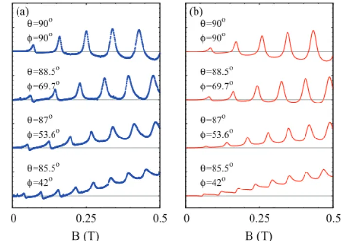
To verify that our model can reproduce the experimentally observed RSA signals in tilted magnetic fields, we performed a series of measurements. The measurements were performed for magnetic field ranging up to 0.5 T, tilt angle varying from 0o to 4.5o, and the temperature set to T =1.2 K. The experimental data are shown in Fig. 3(a) and the modeled signals are presented in Fig. 3(b). All the parameters of the model, apart from the tilt angle, are the same for all modeled curves. In addition, to account for the inhomogeneous ensemble broadening of the hole g factors, the modeled result was averaged according to a Gaussian distribution of gfactors, with the standard deviationsσ⊥ andσ forg⊥and g, respectively. All features of the experimentally measured RSA signal are well reproduced by Eq.(18). These include not only the tilt-dependent oscillation frequency of the signal, but also the quantitative agreement of the positive signal drift and the decrease of the signal oscillation amplitude. Similarly to the TRFR case, however, the number of free fitting parameters is too large to make the fitting unique and reliably infer the values of spin dynamics parameters from the fitting procedure.
Finally, we have to note that in none of our experiments have we observed the inversion of the RSA peaks, which is probably
0 0.25 0.5
RSA signal (arb. units)
B (T) (a)
θ=90o φ=90o
θ=88.5o φ=69.7o
θ=87o φ=53.6o
θ=85.5o φ=42o
0 0.25 0.5
B (T) (b)
θ=90o φ=90o
θ=88.5o φ=69.7o
θ=87o φ=53.6o
θ=85.5o φ=42o
FIG. 3. (Color online) (a) Experimental RSA signals in tilted magnetic fields; (b) modeled RSA signals for tilted magnetic fields with parameters:gt=0.266,g⊥=0.066,σ⊥=1.5%×g⊥, g=0.93, σ=1.5%×g, γ=1010 s−1, κx =κx0=κz=κz0= 2×10⁷s−1.
due to the hole spin decoherence rates being too large. In order to observe this phenomenon, a system of localized hole spins with long decoherence times at temperatures below 2 K and very lowg-factor inhomogeneity would be highly desirable.
One of the possible candidates for such a system might be the strain-free GaAs quantum dots, which were recently prepared usingin situdroplet etching in an MBE system.29
V. CONCLUSION
We have developed a theoretical description of time- resolved Faraday rotation and resonant spin amplification experiments performed onp-doped QWs in magnetic fields tilted from the Voigt geometry. We have found analytical formulas describing both signals and identified physical processes responsible for their origin. The comparison of experimentally obtained signals with these theoretical results allows one, e.g, to get insight into theT1andT2times of holes in the case of a magnetic field applied along an arbitrary axis, by using the obtained angular dependence of the decoherence rates. We also predict that for long enough hole spin dephasing times it should be possible to observe inversion of the RSA peaks induced by the tilted magnetic field. Our theoretical findings have been partly verified by a series of experimental measurements on ap-doped GaAs/Al0.3Ga0.7As single QW we have performed. Specifically, we have shown that our model can account for all the signal features observed experimentally and thus reproduce experimentally measured traces, but not all features predicted theoretically, i.e., the inversion of the RSA peaks, were observed for the sample used in the experiment.
ACKNOWLEDGMENTS
Financial support by the DFG via SPP 1285 and SFB 689, as well as by the Foundation for Polish Science under the TEAM program, cofinanced by the European Regional Development Fund, is gratefully acknowledged.
*k.korzekwa12@imperial.ac.uk
1Spin Physics in Semiconductors, edited by M. I. Dyakonov (Springer, Berlin, 2008).
2T. Korn,Phys. Rep.494, 415 (2010).
3I. Zutic, J. Fabian, and S. Sarma, Rev. Mod. Phys. 76, 323 (2004).
4J. Fabian, A. Matos-Abiague, C. Ertler, P. Stano, and I. Zutic, Acta Physica Slovaca57, 565 (2007).
5M. W. Wu, J. H. Jiang, and M. Q. Weng,Phys. Rep.493, 61 (2010).
6D. Awschalom, D. Loss, and N. Samarth,Semiconductor Spintron- ics and Quantum Computation(Springer, Berlin, 2002).
7D. Heiss, S. Schaeck, H. Huebl, M. Bichler, G. Abstreiter, J. J.
Finley, D. V. Bulaev, and D. Loss,Phys. Rev. B76, 241306 (2007).
8D. Brunner, B. D. Gerardot, P. A. Dalgarno, G. Wust, K. Karrai, N. G. Stoltz, P. M. Petroff, and R. J. Warburton,Science325, 70 (2009).
9M. Syperek, D. R. Yakovlev, I. A. Yugova, J. Misiewicz, M. Jetter, M. Schulz, P. Michler, and M. Bayer,Phys. Rev. B86, 125320 (2012).
10B. Baylac, T. Amand, X. Marie, B. Dareys, M. Brousseau, G. Bacquet, and V. Thierry-Mieg, Solid State Commun. 93, 57 (1995).
11X. Marie, T. Amand, P. Le Jeune, M. Paillard, P. Renucci, L. E.
Golub, V. D. Dymnikov, and E. L. Ivchenko,Phys. Rev. B60, 5811 (1999).
12M. Syperek, D. R. Yakovlev, A. Greilich, J. Misiewicz, M. Bayer, D. Reuter, and A. D. Wieck,Phys. Rev. Lett.99, 187401 (2007).
13T. Korn, M. Kugler, M. Griesbeck, R. Schulz, A. Wagner, M. Hirmer, C. Gerl, D. Schuh, W. Wegscheider, and C. Sch¨uller, New J. Phys.12, 043003 (2010).
14J. J. Baumberg, S. A. Crooker, D. D. Awschalom, N. Samarth, H. Luo, and J. K. Furdyna,Phys. Rev. B50, 7689 (1994).
15J. M. Kikkawa and D. D. Awschalom,Phys. Rev. Lett.80, 4313 (1998).
16Z. Chen, R. Bratschitsch, S. G. Carter, S. T. Cundiff, D. R. Yakovlev, G. Karczewski, T. Wojtowicz, and J. Kossut, Phys. Rev. B 75, 115320 (2007).
17I. A. Yugova, A. A. Sokolova, D. R. Yakovlev, A. Greilich, D. Reuter, A. D. Wieck, and M. Bayer,Phys. Rev. Lett.102, 167402 (2009).
18M. Studer, M. Hirmer, D. Schuh, W. Wegscheider, K. Ensslin, and G. Salis,Phys. Rev. B84, 085328 (2011).
19M. Kugler, K. Korzekwa, P. Machnikowski, C. Gradl, S. Furthmeier, M. Griesbeck, M. Hirmer, D. Schuh, W. Wegscheider, T. Kuhn, C. Sch¨uller, and T. Korn,Phys. Rev. B84, 085327 (2011).
20M. M. Glazov and E. L. Ivchenko, Semiconductors 42, 951 (2008).
21M. Griesbeck, M. M. Glazov, E. Y. Sherman, D. Schuh, W. Wegscheider, C. Sch¨uller, and T. Korn,Phys. Rev. B85, 085313 (2012).
22I. A. Yugova, M. M. Glazov, E. L. Ivchenko, and A. L. Efros, Phys. Rev. B80, 104436 (2009).
23P. Machnikowski and T. Kuhn,Phys. Rev. B81, 115306 (2010).
24E. A. Zhukov, O. A. Yugov, I. A. Yugova, D. R. Yakovlev, G. Karczewski, T. Wojtowicz, J. Kossut, and M. Bayer,Phys. Rev.
B86, 245314 (2012).
25I. A. Yugova, M. M. Glazov, D. R. Yakovlev, A. A. Sokolova, and M. Bayer,Phys. Rev. B85, 125304 (2012).
26M. Kugler, T. Andlauer, T. Korn, A. Wagner, S. Fehringer, R. Schulz, M. Kubov´a, C. Gerl, D. Schuh, W. Wegscheider, P. Vogl, and C. Sch¨uller,Phys. Rev. B80, 035325 (2009).
27P. Le Jeune, D. Robart, X. Marie, T. Amand, M. Brousseau, J. Barrau, V. Kalevich, and D. Rodichev,Semicond. Sci. Technol.
12, 380 (1997).
28H.-P. Breuer and F. Petruccione, The Theory of Open Quantum Systems(Oxford University Press, Oxford, 2002).
29C. Heyn, A. Stemmann, T. Koppen, C. Strelow, T. Kipp, M. Grave, S. Mendach, and W. Hansen,Appl. Phys. Lett.94, 183113 (2009).