magnet Cu 2 OSeO 3
Inaugural-Dissertation zur
Erlangung des Doktorgrades
der Mathematisch-Naturwissenschaftlichen Fakult¨ at der Universit¨ at zu K¨ oln
vorgelegt von
Rolf Baldwin Versteeg
aus Zwolle, Niederlande
K¨ oln
M¨ arz 2019
Vorsitzender der Pr¨ ufungskommission: Prof. Dr. Rer. Nat. A. Rosch
Tag der m¨ undlichen Pr¨ ufung: 03. Mai 2019
uit Nooit meer slapen, Willem Frederik Hermans, 1966
1 Introduction 1 1.1 Magnetic order and disorder, magnetization
dynamics, and light-matter interaction . . . . 1
1.2 Thesis overview . . . . 6
1.3 Bibliography . . . . 8
2 Magnetic order in non-centrosymmetric materials & the chiral magnet Cu
2OSeO
311 2.1 Introduction . . . . 11
2.2 Magnetic order in non-centrosymmetric magnetic materials . 12 2.2.1 Interactions and energy scales . . . . 12
2.2.2 Magnetic phases . . . . 13
2.2.3 Topology . . . . 17
2.3 Cu
2OSeO
3. . . . 20
2.3.1 Structural properties . . . . 20
2.3.2 Electronic properties and excitations . . . . 21
2.3.3 Magnetic order and magnetic excitations . . . . 23
2.3.4 Magneto-electricity . . . . 31
2.4 Acknowledgements and own contributions . . . . 32
2.5 Bibliography . . . . 32
3 Crystal optics and polarization spectroscopy 37 3.1 Introduction . . . . 37
3.2 Polarized light . . . . 38
3.2.1 The electromagnetic wave . . . . 38
3.2.2 Linear and circular polarization . . . . 39
3.2.3 Elliptical polarization . . . . 40
3.3 Fundamental equation of crystal optics . . . . 42
3.4 Dielectric tensor and optical anisotropies . . . . 44
3.4.1 The dielectric tensor . . . . 44
3.4.2 The zero’th order tensor
0ij. . . . 47
3.4.3 Spatial dispersion effects . . . . 48
3.4.4 Magnetization related anisotropies . . . . 49
ix
3.4.5 Magneto-spatial anisotropies . . . . 51
3.5 Linear polarization rotation . . . . 52
3.5.1 Polarization rotation in transmission . . . . 52
3.5.2 Polarization rotation in reflection . . . . 54
3.6 Polarization spectroscopy setup . . . . 55
3.6.1 Overview and schematics . . . . 55
3.6.2 Measurement theory . . . . 57
3.6.3 Sensitivity of the polarization spectrometer . . . . 62
3.7 Kerr spectroscopy of single crystalline SrRuO
3. . . . 63
3.8 Acknowledgements and own contributions . . . . 65
3.9 Bibliography . . . . 65
4 Optically probed symmetry breaking in the chiral magnet Cu
2OSeO
369 4.1 Introduction . . . . 69
4.2 Structure and magnetism . . . . 70
4.3 Experimental methods . . . . 72
4.4 Zero-field optical properties . . . . 72
4.4.1 Optical excitations . . . . 72
4.4.2 Natural optical activity . . . . 75
4.5 Magneto-optical properties . . . . 76
4.5.1 Phase transitions . . . . 76
4.5.2 Field-even rotation and directional dichroism . . . . . 80
4.5.3 Magnitude of the magneto-optical effect . . . . 81
4.6 Conclusions . . . . 83
4.7 Appendix . . . . 83
4.7.1 Temperature dependence of ellipsometry data . . . . . 83
4.7.2 Kerr spectroscopy . . . . 83
4.7.3 Interference of Faraday and Kerr rotated electromagnetic waves . . . . 84
4.8 Own contributions and acknowledgements . . . . 90
4.9 Bibliography . . . . 90
5 Inelastic light scattering from spin cluster excitations in Cu
2OSeO
395 5.1 Introduction . . . . 95
5.2 The Cu
4spin cluster model . . . . 96
5.2.1 Exchange interactions . . . . 96
5.2.2 The isolated cluster model . . . . 96
5.2.3 The interacting cluster model . . . 100
5.2.4 Γ-point excitations: the electron spin resonance spectrum . . . 103
5.2.5 Cluster excitation dispersion: the inelastic
neutron scattering spectrum . . . 104
5.3.4 An example: magnetic scattering in fluorides . . . 113
5.4 Magnetic Raman scattering from spin cluster excitations . . . 115
5.4.1 Experimental details . . . 115
5.4.2 Results and discussion . . . 115
5.5 Conclusions . . . 125
5.6 Own contributions and acknowledgements . . . 126
5.7 Bibliography . . . 126
6 A tunable time-resolved spontaneous Raman spectroscopy setup for probing ultrafast collective excitation and quasiparticle dynamics in quantum materials 129 6.1 Introduction . . . 129
6.2 The time-resolved spontaneous Raman spectroscopy setup . . . 132
6.2.1 Design considerations . . . 132
6.2.2 System overview . . . 134
6.2.3 Detection scheme of choice . . . 139
6.3 Experimental results . . . 139
6.3.1 Optical phonon population and hole continuum dynamics in silicon . . . 139
6.3.2 Time- and momentum resolved scattering in silicon . . . 143
6.3.3 Photoinduced melting of helimagnetic order in the chiral magnet Cu
2OSeO
3. . . 146
6.4 Conclusions and outlook . . . 148
6.5 Own contributions and acknowledgements . . . 149
6.6 Bibliography . . . 150
7 Dynamical resonance quench and Fano interference in spon- taneous Raman scattering from quasiparticle and collective excitations 155 7.1 Introduction . . . 155
7.2 Experimental details . . . 156
7.3 Results and discussion . . . 156
7.4 Conclusions . . . 162
7.5 Appendix . . . 163
7.5.1 Carrier density calibration by laser parameters and Fano interference . . . 163
7.5.2 Transient reflectivity . . . 164
7.5.3 Dynamics at 410 nm probe wavelength . . . 165
7.6 Own contributions . . . 166
7.7 Bibliography . . . 166
8 Coupled dynamics of long-range and internal spin cluster order in Cu
2OSeO
3171 8.1 Introduction . . . 171
8.2 High-energy spin cluster excitations . . . 173
8.3 Photoinduced long-range and internal cluster order dynamics . . . 174
8.4 Conclusions and outlook . . . 179
8.5 Appendix . . . 180
8.5.1 Transient spectra at 15 K, 38 K, and 60 K . . . 180
8.5.2 Supporting data of transient magnetic scattering at T =5 K . . . 183
8.5.3 Temperature increase estimated from heat capacity . . . 185
8.5.4 Different phonons at T = 5 K and F ≈ 2 mJ/cm
2. . . 186
8.5.5 Fluence dependence at T = 5 K . . . 188
8.5.6 Three-temperature model . . . 189
8.5.7 Temperature dependent time constants . . . 190
8.5.8 Transient absorption spectroscopy measurement . . . 191
8.6 Own contributions and acknowledgements . . . 192
8.7 Bibliography . . . 193
Summary 197
Zusammenfassung 199
Samenvatting 201
List of publications 211
Offizielle Erkl¨ arung 213
Lebenslauf 215
Introduction
1.1 Magnetic order and disorder, magnetization dynamics, and light-matter interaction
Magnetism has fascinated mankind over multiple millenia. The study of magnetism can be traced back as far as to the ancient Greek world, when Thales of Milete observed an attractive force originating from µαγν ητ ις ´ λ´ ιθoς (“magnesian stone”), a material which we nowadays know as mag- netite, or Fe
3O
4. Thales of Milete had the idea that magnetite contains a soul which can attract iron.
1It would take until the the 20
thcentury, - where humankind landed in the era of quantum mechanics -, to realize that this attractive force actually ultimately originates in a cooperative spinning of ∼ 10
23electrons.
2The quest to understand how complex phenomena such as magnetic order and disorder, - but also superconductivity, multi- ferroicity, optical properties, or in general the physical properties of matter -, arise from the cooperative interaction between electrons and the atomic nuclei in a solid, is the domain of condensed matter physics. Obviously, this endeavour to answer fundamental questions on the quantum nature of ma- terials runs parallel with an everlasting drive to develop novel technological applications which can exploit these emergent physical phenomena.
3One of the most fundamental concepts related to magnetism is order and disorder. We know that the interaction energy between two electrons depends on it’s charge, but also on the spin of the electrons. Whether two spins “want” to align parallel (↑↑) or antiparallel (↑↓), depends on the sign of the exchange integral J.
4When for ∼ 10
23electron spins it becomes en- ergetically favourable to all align collinearly with the spins pointing in the same direction, we call this ferromagnetic order. Thermal fluctuations may overcome the exchange energy at temperatures of the order T ∼ J /k
B(with k
Bbeing the Boltzmann constant), and the spins become randomly ori- ented, in which case we have paramagnetic disorder. This order-to-disorder crossover is a phase transition, which we can “quantify” by an increase in en-
1
2 Chapter 1: Introduction tropy S. Phase transitions mostly go hand in hand with a symmetry change, for instance, the paramagnet has a higher symmetry than the magnetically ordered phase. Symmetry thus provides us with another good handle to describe the “amount” of order and disorder, or more formally, the state of matter.
Over the course of the 20
thcentury a wide range of more complicated ordering types have been added to the magnetic ordering palette, examples of which include spin helices and spin cycloids. Such phases stabilize due to a competition between Heisenberg and Dzyaloshinski-Moriya exchange in magnets with broken spatial inversion symmetry.
5This type of magnetism will, among others, be central to this thesis work. Interestingly enough, such type of noncollinear ordering can also be observed in deceivingly “sim- ple” elemental rare-earth metals like dysprosium, where 4f -moments cou- ple through the conduction electron mediated RKKY-interaction (Ruder- man–Kittel–Kasuya–Yosida).
6Figure 1.1: The here shown skyrmion lattice phase appears as a hexagonal lat- tice of spin vortices. The figure has been adapted from Ref. 7 (published under a Creative Commons CC BY-NC-ND 2.5 license).
The above mentioned examples of magnetic order can perhaps by now be regarded as “classical” magnetic states of matter. However, the 2008 exper- imental discovery of skyrmion lattice order
8is just one out of many recent examples which show that today’s magnetism research is as interesting, - if not more -, as it was before. Figure 1.1 provides a beautiful illustration of a so-called skyrmion lattice.
7This ordering corresponds to a hexagonal lattice of topologically protected spin vortices, known as skyrmions. This type of magnetic order can be stabilized in, among others, chiral magnets.
There are numerous other types of “exotic” magnetic order, but also types of disorder which go beyond simple paramagnetism or diamagnetism, which are studied nowadays.
The devil is in the detail when it comes down to the question whether
magnetic moments can order, or whether they stay disordered. The first
situation where we may expect to encounter nontrivial magnetic disorder
are low-dimensional systems, i.e. 1-dimensional and 2-dimensional magnets.
of thermally excited magnons should diverge at finite temperature, and 1- dimensional and 2-dimensional magnetic order should not exist. At T = 0 K, where there are no thermal fluctuations, but nevertheless still quantum fluc- tuations, 2-dimensional order can exist, but 1-dimensional order still cannot exist. This is the essence of the so-called Mermin-Wagner-Berezinskii the- orem.
2That low dimensional (partial) long-range order however has been observed, for instance spin chains in CsCoCl
3,
2ferromagnetic layers in hy- brid organic-inorganic materials,
9or antiferromagnetic layers in perovskite materials,
2is due to the fact that the disorder restriction imposed by the Mermin-Wagner-Berezinskii theorem gets lifted by competing exchange in- teractions, magnetic anisotropy, and weak inter-layer or inter-chain interac- tions.
2Competing interactions can also lead to highly correlated forms of dis- order. The dominant symmetric Heisenberg coupling between spin-orbit entangled j =
12moments on a honeycomb lattice exactly cancel out, and leave higher-order exchange processes, like bond-directional exchange, the relevant exchange interaction. One such a type of coupling, the Kitaev- exchange interaction, cannot be simultaneously satisfied along all bonds on a hexagonal lattice, i.e. the spins are exchange frustrated.
10In this case a highly nontrivial phase with short-range spin correlations emerges, known as the Kitaev spin liquid. One prime candidate for this material with novel fermionic Majorana excitations is α-RuCl
3.
11Figure 1.2: Geometric frustration: for antiferromagnetically (J
AF) coupled Ising (up or down) spins on a triangle the third spin cannot align.
Frustration can also appear for simpler cases where only the symmet- ric Heisenberg exchange is relevant. For triangular, hexagonal and kagome lattice geometries there are cases where spins cannot uniquely order for cer- tain spin dimensionalities (Ising, XY, or Heisenberg spin) and interactions.
For instance, for antiferromagnetically coupled Ising spins (spins which can
only point up or down) on a triangle there is no unique magnetic order-
ing possible, as illustrated in Fig. 1.2. In this case we can say that the
4 Chapter 1: Introduction spins are geometrically frustrated, with as a result that the spins stay dis- ordered.
12But again, because the spins couple, we still have a correlated type of disorder, known as a spin liquid phase. Spins on a three dimensional pyrochlore lattice which are ferromagnetically coupled through the Heisen- berg exchange interaction are also frustrated. This situation is drawn in Fig. 1.3a. Each exchange path (grey) has an equal strength. Even though at low temperatures the magnetic moments (light blue) can order, there is no unique magnetic ground state. This “ordered disorder” is named spin ice.
12Small distortions in the tetrahedra of the pyrochlore lattice lead to a whole different physical picture, where strong (full lines) and weak (dashed lines) exchange paths can be identified, as seen in Fig. 1.3b. In this situation the frustration is lifted and the spins may form a unique long-range order- ing pattern consisting of long-range ordered tetrahedral triplet spin clusters (cluster spins indicated in grey), as shown in Fig. 1.3c. We will see that this type of ordering occurs in the central material of this thesis, namely the Mott insulator Cu
2OSeO
3.
13In this thesis work it will be discussed that this type of magnetic order can be regarded as a solid-state spin-analog of a molecular crystal.
14From the aforementioned examples we see the im- portance of the crystallographic structure for magnetic (dis)order. We can thus safely say that complex lattice geometries and low dimensionality are a recipe for highly rich physics.
Figure 1.3: a) Spins (light blue) on a pyrochlore lattice. Each exchange path (grey) has an equal strength. In this case magnetic order can exist, but there is no unique spin configuration possible. This is called spin ice. Figure adapted from Ref. 15. Published under a Creative Commons Attribution-ShareAlike 4.0 International (CC BY-SA 4.0) licence. b) The distorted pyrochlore lattice, with spins in grey. In this case strong (full lines) and weak (dashed lines) exchange paths of predominantly ferromagnetic (blue) and antiferromagnetic (red) character can be identified. The strong exchange leads to spin cluster formation. c) The spin clusters are indicated in light blue. We can regard this magnetic ground state as a solid-state analog of a molecular crystal. Such a ground state is observed in the main studied material of this thesis, the Mott insulator Cu
2OSeO
3.
Light-matter interaction is particularly sensitive to symmetry break-
ing.
16Optical spectroscopy therefore is an ideal tool to study magnetic
magnetically ordered (or placed inside a magnetic field). In the case of finite magnetization, such as ferromagnetic or conical spin ordering, we can ob- serve a light polarization rotation proportional to the magnetization upon transmission through a sample, known as Faraday rotation.
17This can be used as a sensitive optical probe for magnetic order and disorder, and it even allows to detect the skyrmion lattice phase in Cu
2OSeO
3, as shown in this thesis work. Chiral molecules and crystals allow for a polarization rotation known as natural optical activity.
16We can use this optical phe- nomenon to determine crystallographic chirality. These optical phenomena are well-known for more than over a century. However, in modern times new
“exotic” optical phenomena were discovered, which for instance result from the combined broken spatial inversion and time-reversal symmetry. We will see that such an exotic magneto-optical phenomenon, known as magnetochi- ral dichroism, can serve as a probe of magnetic chirality.
18At finite temperatures the magnetic order is not a static, frozen col- lection of spins, but instead thermal fluctuations of the spin order exist, namely spin waves, or magnons. These spin waves are “magnetic dynam- ics at thermodynamic equilibrium”. Inelastic scattering techniques like in- elastic neutron scattering and spontaneous Raman spectroscopy may give us insight into magnetic equilibrium dynamics. However, we can also use strong external perturbations like magnetic and electric field pulses to per- turb the thermodynamic equilibrium, and drive the (magnetic) system into an out-of-equilibrium state. After such a strong disturbance the magnetic system eventually will relax back into its thermodynamic equilibrium within a characteristic timescale. These relaxation timescales are governed by the coupling between lattice, electronic, orbital and magnetic degrees of freedom, and measuring these timescales provides us insight into relaxation channels between the different degrees of freedom in a solid. In this case we speak of nonequilibrium magnetization dynamics.
The fastest perturbation at our disposal to study nonequilibrium dynam-
ics is an ultrashort light pulse. Pulsed lasers have opened the possibility to
probe magnetization dynamics and even control magnetic order on fem-
tosecond timescales. The research field studying these ultrafast phenomena
has been dubbed femtomagnetism and is a highly active part of condensed
matter physics.
19Examples on a fundamental level include the electron-
spin scattering induced ultrafast melting of ferromagnetic order in nickel,
20and optical control of the antiferromagnetic helical pitch through injection
of photoinduced carriers in dysprosium.
6Recent scientific advances with a
truly high potential towards applications include all-optical magnetization
switching,
21and picosecond optical writing and read-out of magnetic bits.
22In the case of melting of ferromagnetic order in nickel, or modulating the he-
lical pitch in dysprosium we change or reduce the magnetic order parameter,
but the nature of the magnetic order remains the same. However, optical
6 Chapter 1: Introduction excitation also allows to truly alter the nature of the magnetic phase. An example is the femtosecond activation of magnetoelectricity in CuB
2O
4.
23Here, an additional type of ferroic order, in this case ferroelectricity, is tran- siently stabilized besides magnetic order. In the case of CuB
2O
4the magne- toelectric phase can also be stabilized through the static control parameters of magnetic field and temperature. However, photoexcitation even allows to create metastable phases not accessible under equilibrium conditions.
24As such, a new dimension in the phase space of a material can be uncovered.
Again symmetry changes play a role here, but now in a nonequilibrium way.
In this thesis it will be discussed that the strong symmetry sensitivity of the spontaneous Raman scattering process can be exploited in the time- resolved variant of the technique in order to elucidate symmetry changes across photoinduced phase transitions.
25, 261.2 Thesis overview
The Mott insulator Cu
2OSeO
3has a “solid-state spin molecular”-like helical ground state, and a rich set of metamagnetic phases. The optically probed order and dynamics of this chiral cluster magnet is the central topic of this thesis.
In chapter 2 the ground state magnetic order and field induced meta- magnetic phases of non-centrosymmetric magnetic materials is discussed.
These magnetic phases result from a competition between Heisenberg ex- change, Dzyaloshinskii-Moriya-exchange, magnetic anisotropy, and the Zeeman-coupling when a magnetic field is applied. The chiral magnet Cu
2OSeO
3is introduced. We will see that Cu
4triplet clusters form the relevant spin entity for the formation of long-range magnetic order in this Mott insulator. Under an applied field different metamagnetic phases form, among others a topologically protected skyrmion lattice phase. The cluster formation and long-range order leads to a complex spin wave spectrum. Fur- thermore, the lattice and electronic properties of Cu
2OSeO
3are discussed.
Broken spatial inversion symmetry, time-reversal symmetry, and their combined presence in chiral magnets leads to a rich set of linear optical phenomena, as is discussed in chapter 3. The fundamental equation of crystal optics is derived, and it is argued why in the optical range of the electromagnetic spectrum one can describe the light-matter interaction in terms of an effective dielectric constant dependent on magnetization and the wave vector. The for this thesis work constructed polarization spectroscopy setup is described, as well as the measurement theory behind the technique.
The working of the setup is illustrated with magneto-optical Kerr effect measurements of the ferromagnetic 4d-metal oxide SrRuO
3.
Chapter 4 focuses on the linear optical properties of Cu
2OSeO
3. It is
shown that the broken spatial inversion symmetry leads to strong dipole ac-
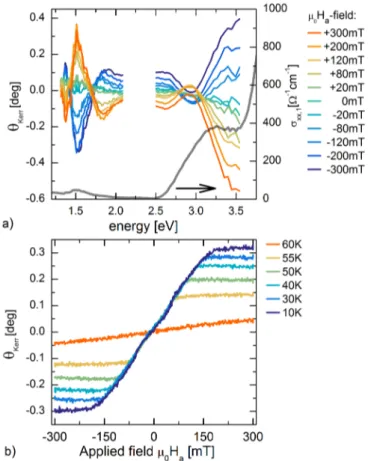
to natural optical activity. The natural optical activity may be used as a probe for structural chirality, and shows sensitivity to magnetic ordering, evidencing a finite magneto-electric coupling. A strong Faraday-rotation is observed, which is discussed to originate from spin cluster formation and the relative ease of domain reorientation. The strong magneto-optical re- sponse is used to probe the metamagnetic phase transitions. This allowed to all-optically map the metamagnetic phase diagram, including the skyrmion lattice phase.
Previous work has shown that the long-range spin cluster ordering results in a characteristic spin wave spectrum, which can be divided into low-energy external and high-energy internal spin cluster excitations. In chapter 5 these works are summarized. For this thesis work spontaneous Raman spec- troscopy was used to probe spin cluster transitions at the Brillouin zone center. The Raman-scattering activity of the spin cluster transitions is dis- cussed to originate from the Elliot-Loudon light scattering mechanism. The temperature dependent scattering response of the high-energy internal clus- ter modes shows a crossover from broad continuum scattering above the critical temperature T
Cinto well-defined magnetic modes below T
C, which is discussed to originate from a change of the character of the high-energy cluster modes. Above T
Cthe high-energy spin cluster excitations corre- spond to localized internal cluster excitations, while in the long-range or- dered phase the high-energy modes acquire dispersion, and correspond to optical magnons.
For this thesis work an ultrafast time-resolved spontaneous Raman spec- troscopy setup (TiReRa) was designed and constructed. In chapter 6 the possibilities of the technique are discussed, such as measuring photoinduced quasiparticle and collective excitation population dynamics, and detecting symmetry changes across photoinduced phase transitions. Additionally, the revelant design parameters to optimize the setup for probing nonequilibrium dynamics of quantum materials are discussed. The TiReRa laser system, table optics, Raman-microscopy interface, and spectrometer are presented.
Three case studies illustrate the working of the setup. The first focuses on longitudinal-optical phonon population, Raman tensor, and hole dynam- ics in silicon. The second study focuses on time-and momentum resolved phonon scattering in silicon. A short appetizer to the results of the last chapter is given, in which the photoinduced nonequilibrium dynamics of Cu
2OSeO
3is presented.
When discussing time-resolved Raman spectroscopy one may be tempted
to solely focus on population dynamics, and neglect the role of the Raman
tensor in the time-domain. In our test experiments on silicon presented in
chapter 6 we observed a Raman tensor quench, demonstrating that Raman
tensor dynamics however is an important factor in correctly interpreting
the time-resolved spontaneous Raman scattering response of a photoexcited
8 Chapter 1: Introduction material. In chapter chapter 7 it is discussed in greater detail how si- multaneous detection of both anti-Stokes and Stokes scattering permits to disentangle the Raman tensor and genuine population dynamics. The Ra- man tensor quench in silicon is discussed to originate from the photoinduced hole carrier population. A second effect of the optically excited carriers is an enhancement of the longitudinal optical phonon Fano asymmetry.
The steady-state Raman scattering study described in chapter 5 estab- lished that the high-energy spin cluster excitations can be used as an optical probe of long-range and internal spin cluster order. In chapter 8 we use the newly constructed time-resolved Raman spectroscopy setup TiReRa to probe the photoinduced near-equilibrium spin and lattice dynamics of the helimagnetic phase in Cu
2OSeO
3. Multiple ps-decade spin-lattice relaxation dynamics is observed, evidencing a separation of the order parameter dy- namics into disordering of long-range and internal spin cluster order. The observations of the steady-state and time-resolved Raman study exemplify that Cu
2OSeO
3can be regarded as a solid-state molecular crystal of spin nature.
1.3 Bibliography
[1] N. Ida,
Engineering electromagnetics, 3rded. (Springer, 2015).
[2] S. Blundell,
Magnetism In Condensed Matter, (Oxford University Press, 2001).[3] D. N. Basov, R. D. Averitt, and D. Hsieh, Towards properties on demand in quantum materials, Nat. Mater.
16, 1077 (2017).[4] P. Fazekas,
Lecture notes on electron correlation and magnetism, volume 5(World scientific, 1999).
[5] P. Bak and M. H. Jensen, Theory of helical magnetic structures and phase transitions in MnSi and FeGe, J. Phys. C: Solid St. Phys.
13, L881 (1980).[6] M. C. Langner, S. Roy, A. F. Kemper, Y.-D. Chuang, S. K. Mishra, R. B. Versteeg, Y. Zhu, M. P. Hertlein, T. E. Glover, K. Dumesnil, and R. W. Schoenlein, Scattering bottleneck for spin dynamics in metallic helical antiferromagnetic dysprosium, Phys.
Rev. B
92, 184423 (2015).[7] K. Everschor,
Current-induced dynamics of chiral magnetic structures: skyrmions, emergent electrodynamics and spin-transfer torques, PhD thesis, Universit¨at zu K¨ oln, 2012.
[8] S. M¨ uhlbauer, B. Binz, F. Jonietz, C. Pfleiderer, A. Rosch, A. Neubauer, R. Georgii, and P. B¨ oni, Skyrmion lattice in a chiral magnet, Science,
323, 915 (2009).[9] L. J. de Jongh and A. R. Miedema, Experiments on simple magnetic model systems, Adv. Phys.
23, 1 (1974).[10] S. Trebst, Kitaev materials, e-print arXiv:1701.07056 [cond-mat.mtrlsci] (2017).
[11] A. Banerjee, C. A. Bridges, J.-Q. Yan, A. A. Aczel, L. Li, M. B. Stone, G. E. Granroth, M. D. Lumsden, Y. Yiu, J. Knolle, S. Bhattacharjee, D. L. Kovrizhin, R. Moessner, D. A. Tennant, D. G. Mandrus and S. E. Nagler, Prox- imate kitaev quantum spin liquid behaviour in a honeycomb magnet, Nat. Mater.
15, 733 (2016).
[13] O. Janson, I. Rousochatzakis, A. A. Tsirlin, M. Belesi, A. A. Leonov, U. K. R¨ oßler, J. Van den Brink, and H. Rosner, The quantum nature of skyrmions and half- skyrmions in Cu
2OSeO
3, Nat. Commun.
5, 5376 (2014).[14] S. V. Streltsov and D. I. Khomskii, Orbital physics in transition metal compounds:
new trends, Phys. Usp.
60, 1121-1146 (2017).[15] https://commons.wikimedia.org/wiki/File:Fragment of pyrochlore lattice in spin ice state.png, figure released under a Creative Commons Attribution-ShareAlike 4.0 International (CC BY-SA 4.0) licence.
[16] A. Glazer and K. G. Cox,
Classical linear crystal opticsin
International Tables for Crystallography, Vol. D, (John Wiley & Sons, Ltd., 2006), Chapter 1.1.6.[17] P. S. Pershan, Magneto-Optical Effects, J. Appl. Phys.
38, 1482 (1967).[18] G. L. J. A. Rikken and E. Raupach, Observation of magneto-chiral dichroism, Nature
390, 493 (1997).[19] A. Kirilyuk, A. V. Kimel, and T. Rasing, Ultrafast optical manipulation of magnetic order, Rev. Mod. Phys.
82, 2731 (201[20] E. Beaurepaire, J. -C. Merle, A. Daunois, and J. -Y. Bigot, Ultrafast spin dynamics in ferromagnetic nickel, Phys. Rev. Lett.
76, 4250 (1996).[21] M. Savoini, R. Medapalli, B. Koene, A. R. Khorsand, L. Le Guyader, L. Du` o, M. Fi- nazzi, A. Tsukamoto, A. Itoh, F. Nolting, A. Kirilyuk, A. V. Kimel, and T. Rasing, Highly efficient all-optical switching of magnetization in GdFeCo microstructures by interference-enhanced absorption of light, Phys. Rev. B
86, 140404 (2012).[22] A. Stupakiewicz, K. Szerenos, D. Afanasiev, A. Kirilyuk, and A. V. Kimel, Ultrafast nonthermal photo-magnetic recording in a transparent medium, Nature
542, 71(2017).
[23] D. Bossini, K. Konishi, S. Toyoda, T. Arima, J. Yumoto and M. Kuwata-Gonokami, Femtosecond activation of magnetoelectricity, Nat. Phys.
14, 370 (2018).[24] D. Fausti, R. I. Tobey, N. Dean, S. Kaiser, A. Dienst, M. C. Hoffmann, S. Pyon, T. Takayama, H. Takagi, and A. Cavalleri, Light-induced superconductivity in a stripe-ordered cuprate, Science
331, 189 (2011).[25] D. Fausti, O. V. Misochko, and P. H. M. van Loosdrecht, Ultrafast photoinduced structure phase transition in antimony single crystals, Phys. Rev. B
80, 161207(2009).
[26] D. Fausti and P. H. M. van Loosdrecht, in Chapter 14:
Time-resolved Raman scat- teringof
Optical Techniques for Solid-State Materials Characterization, edited byR. P. Prasankumar and A. J. Taylor, (CRC Press, Boca Raton London New York,
2012).
10 Chapter 1: Introduction
Magnetic order in
non-centrosymmetric materials & the chiral magnet Cu 2 OSeO 3
2.1 Introduction
Non-centrosymmetric materials show a variety of magnetic ground states and metamagnetic phases due to the competition of Heisenberg-exchange, Dzyaloshinskii-Moriya-exchange, magnetic anisotropy, and the Zeeman cou- pling when a magnetic field is applied.
1, 2In this chapter an overview of the relevant magnetic interactions and resulting metamagnetic phases will be given. A magnetic phase of special interest is the skyrmion lattice phase.
This phase consists of vortex-like topologically stable nanometric spin structures,
3, 4which in a range of different bulk magnetic materials “crystal- lize” in a lattice consisting of tubes of magnetic skyrmions.
5The wave-like interpretation of the skyrmion lattice is presented, as well as an intuitive description of the nontrivial topology of the skyrmion phase.
This chapter furthermore provides an introduction to the central mate- rial of this thesis, namely the chiral magnet Cu
2OSeO
3, which was the first insulating material to be discovered to hosts a skyrmion lattice under an ap- plied field. The insulating character leads to the possibility of electric field control of the skyrmion phase through magnetoelectric coupling, i.e. a type of control which cannot be realized in metallic and semiconducting skyrmion host counterparts like MnSi and FeGe,
3even though these materials possess similar magnetic phase diagrams. Possibly more surprising is that, unlike other skyrmion hosts such as MnSi and FeGe, the long-range magnetic order in Cu
2OSeO
3is composed of localized spin clusters, as opposed to localized single spins.
6This formation of long-range ordered clusters results from the
11
12 Chapter 2. Magnetic order & Cu
2OSeO
3strong and weak exchange energy scales present in Cu
2OSeO
3, as discussed in this chapter. Furthermore, an overview of the resulting spin cluster exci- tations and low-energy chiral excitations will be given.
2.2 Magnetic order in non-centrosymmetric mag- netic materials
2.2.1 Interactions and energy scales
In magnets with broken inversion symmetry the symmetric Heisenberg- exchange term J
ijS ~
i· S ~
jtypically is the strongest energy scale after which the anti-symmetric Dzyaloshinskii-Moriya-exchange (DM-exchange) D ~
ij· S ~
i× S ~
jfollows.
2(Anti-)symmetry refers to whether the terms change sign when the spins are exchanged. The Heisenberg-exchange leads to parallel or anti- parallel spin aligment depending on the sign of J
ij. The case of parallel spin alignment is illustrated in Fig. 2.1a.
Figure 2.1: a) Illustration of ferromagnetic spin alignment through the symmetric Heisenberg exchange interaction. Here the interaction J
ijbetween the spins S ~
iand S ~
jis of negative sign, which leads to a ferromagnetic spin alignment. b) Illustration of anti-symmetric Dzyaloshinski-Moriya exchange, which leads to a canted spin alignment. The green ion is a ligand ion which breaks inversion symmetry between the spins S ~
iand S ~
j. The direction of the DM-vector in the cartoon points out-of- plane, which leads to spin canting along the bond ~ r
ij.
The DM-exchange favours a canted spin alignment as illustrated in
Fig. 2.1b. The DM-interaction is present when there is no inversion sym-
metry between the spin sites and is thus present in non-centrosymmetric
magnets.
7Spin-orbit coupling is a second prerequisite for the DM-exchange
interaction. The DM-vector D ~
ijcan have a component parallel and perpen-
dicular to the connecting vector ~ r
ijbetween the spins. The specific form
of the DM-interaction depends on the crystallographic symmetry.
1, 2Mag-
netocrystalline and shape anisotropy also influence the pointing direction.
8The DM-interaction energy is minimized when the spins S ~
iand S ~
jcant at
right angles in the plane perpendicular to D ~
ij. For the case D ~
ij⊥ ~ r
ij, as
depicted in Fig. 2.1b, spins cant along the connecting vector ~ r
ijwhereas for
DM-interaction energy is an order 10 smaller than the Heisenberg exchange.
9, 10A material with an exceptionally large DM-interaction is the main investigated materials of this thesis work, namely Cu
2OSeO
3. For some exchange paths the DM-exchange to Heisenberg exchange ratio can be as large as O ∼ 10
−1(Refs. 10, 11).
A smaller energy scale relevant for the magnetic order in
non-centrosymmetric materials results from magnetocrystalline anisotropy (or crystal field anisotropy). This interaction describes the coupling of spins to the crystal lattice through spin-orbit interaction, where it should be un- derstood that the orbital orientation is dictated by Coulomb interaction with the surrounding ligand field. The magnetocrystalline anisotropy thus dictates the orientation of the magnetic moment with respect to the crystal surrounding, or more formally stated it breaks the rotational symmetry.
7, 12This energy scale is again an order O ∼ 10
−2smaller than the Dzyaloshinskii- Moriya-exchange.
The potential energy of a magnetic moment in a magnetic field is given by the Zeeman coupling term -µ·B. The energy scale is gµ
BB, where g is the g-factor of the magnetic moment, and B gives the magnetic field strength.
7The last term of importance is the thermal energy k
BT , with k
Bbeing the Boltzmann constant, and T being the temperature. Table 2.1 provides a summary of all relevant energy scales.
Table 2.1: Energy scales relevant to the formation of magnetic order in non- centrosymmetric materials. The left column gives the interaction type. The right column gives the order of magnitude with respect to the Heisenberg exchange, which is the dominant contribution.
energy order of magnitude (compared to J
ij)
Heisenberg exchange J
ij1
DM-exchange D ~
ij10
−2magnetocrystalline anisotropy 10
−4Zeeman potential gµ
BB 10
−4thermal energy k
BT 1
2.2.2 Magnetic phases
Under the presence of an external magnetic field different metamagnetic
phases are stabilized in a non-centrosymmetric magnet.
13Which types of
magnetic order are thermodynamically stable can be inferred by minimizing
the Free energy functional F (M), which is the sum of the different interac-
14 Chapter 2. Magnetic order & Cu
2OSeO
3tion energies integrated over a macroscopic volume. Here M indicates the magnetization.
7For a chiral magnet in a magnetic field B the Free energy F(M) is given in a continuum approximation
12, 14form as:
F(M) ≈ Z
d
3r
r
0M
2+ J (∇M)
2+ U M
4+ 2D∇M · (∇M × M) − M · B + F
anisotropy(2.1) The r
0M
2, U M
4and J(∇M)
2terms are the Heisenberg exchange terms.
Here r
0, U , and J are phenomenological parameters which depend on micro- scopic parameters such as the spin length S, the distance a between spins, the amount of nearest-neighbours and the Heisenberg exchange integral.
7The Free energy is minimized for a spontaneous magnetization +M or −M when only these first three terms are present with the right sign and magni- tude for the phenomenological parameters. This can describe ferromagnetic order.
7The term 2D∇M · (∇M × M) term gives the DM-energy contribution.
Microscopically this term depends on parameters such as the spin-orbit cou- pling strength, the DM-exchange integral, the distance between spins, the spin lengths and the amount of nearest-neighbours. The DM-exchange al- lows for the formation of cycloidal or helical order. The crystallographic point group dictates the form of the DM-interaction and thus whether spins preferentially cant parallel or perpendicular to the connecting vector r be- tween spins. In the first case spin cycloids form (point group C
nvwith n = 1, 2, 3, 4, 6 and T
d), such as in GaV
4S
8(C
3v).
15In the second case spin helices form (point groups T and O), such as in Cu
2OSeO
3,
16FeGe,
14Fe
1−xCo
xSi,
17and MnSi (point group T ).
14, 18In chiral magnets the magnetic ground state is a helix,
2with continuum approximation solution:
M(r) = M
0~ e
xcos(q · r) + ~ e
ycos(q · r)
(2.2) The helix only has a transversal spin component. q =
2πλis the helix’
wave vector, where λ is the length of the helix, which is dictated by the ratio
| D
ij/J
ij|. (Ref. 14 and Ref. 2) A depiction of helical spin ordering is given in Fig. 2.2a.
The spin cycloid both has a transversal and longitudinal spin component, and is given by:
M(r) = M
0~ e
ycos(q · r) + ~ e
zcos(q · r)
(2.3)
A depiction of spin cycloid ordering is shown in Fig. 2.2b. The functional
F(M) up till this point was described to be isotropic. The helix and cycloid
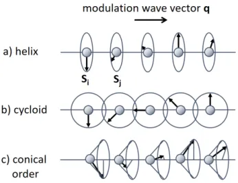
Figure 2.2: a) Helimagnetic spin order. b) Cycloid spin order. c) Conical spin order.
q-vector, or direction of spontaneous magnetization can thus point in an arbitrary direction r in real space. The Zeeman term −M·B describes the coupling to the magnetic field B, and breaks the rotational isotropy. The Zeeman term microscopically depends on the g-factor, as discussed in the previous paragraph. A conical type of spin ordering is stabilized when a magnetic field is applied parallel to the helimagnetic wavevector q, as de- picted in Fig. 2.2c. For sufficiently strong external fields the Free energy F(M) is minimized for field-polarized ferromagnetic or ferrimagnetic order with magnetization M(r) = M
0z pointing along the magnetic field direction.
For a small temperature range just below T
C, and small field range, the skyrmion lattice phase is stabilized.
19The skyrmion lattice (SkL) phase forms as a triple-q hybridized state,
3, 20consisting of tubes of skyrmions,
5where the magnetization in the continuum approximation is given as:
M(r) ≈ M
0+
3
X
i
M
qi(r + ∆r) (2.4)
The M
0term is a uniform magnetization component induced by the Zeeman-term. The second term is a superposition of three helices (or cy- cloids), with a phase shift with respect to each other. For the condition
3
X
i
![Figure 2.16: The inverse Faraday experiment of Ogawa et al. (Ref. 52): a) Probing is performed with 2.2 eV probe pulses in a Voight-geometry with the external mag-netic field applied along H a k [¯ 110]](https://thumb-eu.123doks.com/thumbv2/1library_info/3698379.1505904/44.892.234.591.574.867/figure-inverse-faraday-experiment-probing-performed-geometry-external.webp)